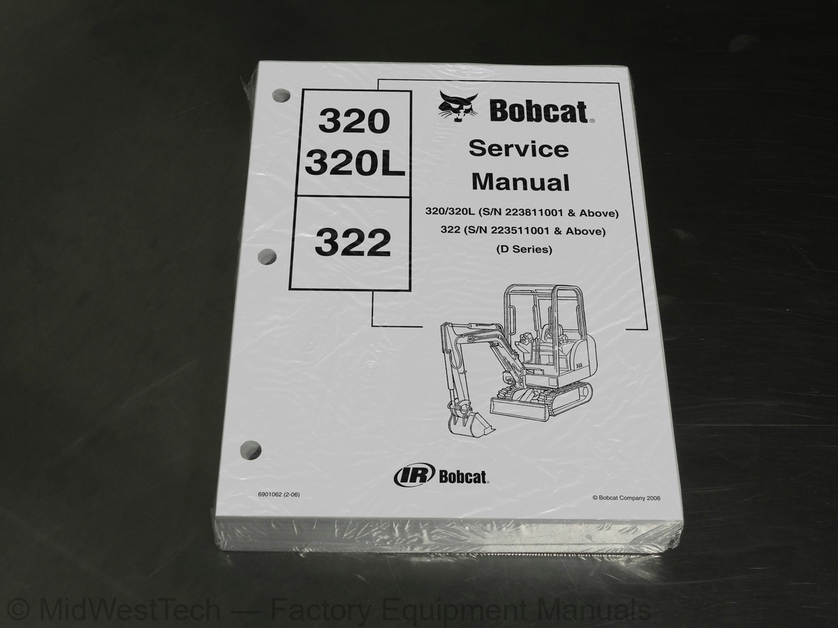
Bobcat 320, 320L, 322 D Series Excavator Service Manual
728 pages · Publication 6901062_2_06
Added to your cart. View cart
What's inside
From the manual's own table of contents: 16 sections, 460 entries. See sample pages (PDF, 391 KB)
FOREWORD7 topics
- SAFETY INSTRUCTIONS
- Fire Prevention
- SERIAL NUMBER LOCATIONS
- Excavator Serial Number
- Engine Serial Number
- DELIVERY REPORT
- BOBCAT EXCAVATOR IDENTIFICATION
LIFTING AND BLOCKING THE EXCAVATOR46 topics
- Procedure
- SWING LOCK
- Operation
- LIFTING THE EXCAVATOR
- 3-Point Lift Procedure
- OPERATOR CAB
- Emergency Exit
- Cab Door
- Front Window
- TRANSPORTING THE EXCAVATOR
- TAILGATE
- Opening And Closing The Tailgate (S/N 223513558 & Below And 223812078 & Below)
- Opening And Closing The Tailgate (S/N 223513559 & Above And 223812079 & Above)
- Adjusting The Bumper
- SERVICE SCHEDULE
- Chart
- AIR CLEANER SERVICE
- Daily Check
- Replacing The Filters
- HEATER AIR FILTERS
- Recirculation Filter
- Fresh Air Filter
- ENGINE COOLING SYSTEM
- Cleaning The Cooling System
- Checking Coolant Level
- Replacing The Coolant
- FUEL SYSTEM
- Fuel Specifications
- Filling The Fuel Tank
- Removing Water From The Fuel Filter
- Replacing The Fuel Filter
- Draining The Fuel Tank
- Removing Air From The Fuel System
- ENGINE LUBRICATION SYSTEM
- Checking Engine Oil
- Replacing Oil And Filter
- HYDRAULIC SYSTEM
- Checking And Adding Fluid
- Diagnostic Couplers
- Replacing The Hydraulic Filter
- Replacing The Hydraulic Fluid (S/N 223512347 & Above and 22384377 & Above)
- LUBRICATING THE EXCAVATOR
- FINAL DRIVE CASE
- Checking Oil Level
- Draining Final Drive Case
- SPARK ARRESTOR MUFFLER
HYDRAULIC/HYDROSTATIC SCHEMATICS170 topics
- HYDRAULIC SYSTEM INFORMATION
- Troubleshooting Chart
- BOOM CYLINDER
- Checking The Boom Cylinder
- Removal and Installation
- Parts Identification
- Disassembly
- Assembly
- ARM CYLINDER
- Checking The Arm Cylinder
- Removal and Installation
- Parts Identification
- Disassembly
- Assembly
- BOOM SWING CYLINDER
- Checking The Boom Swing Cylinder
- Removal and Installation
- Parts Identification
- Disassembly
- Assembly
- BUCKET CYLINDER
- Checking The Bucket Cylinder
- Removal and Installation
- Parts Identification
- Disassembly
- Assembly
- BLADE CYLINDER
- Checking The Blade Cylinder
- Removal and Installation
- Parts Identification
- Disassembly
- Assembly
- TRACK FRAME EXPANSION CYLINDER
- Checking The Track Frame Expansion Cylinder
- Removal And Installation
- Parts Identification
- Disassembly
- Assembly
- MAIN RELIEF VALVE
- Testing And Adjusting The Main Relief Valve
- PORT RELIEF VALVES
- Testing And Adjusting The Port Relief Valve Pressure (S/N 223512064 & Below and 223813552 & Below)
- Testing And Adjusting The Port Relief Valve Pressure (S/N 223512065 & Above and 223813553 & Above)
- CROSSPORT RELIEF VALVES
- Testing And Adjusting The Crossport Relief Valve
- PRESSURE REDUCING VALVE
- Testing And Adjusting The Pressure Reducing Valve
- HYDRAULIC CONTROL VALVE ASSEMBLY (S/N 223512346 & BELOW AND 223814376 & BELOW)
- Description
- Removal and Installation
- Control Valve Identification [Figure 20-40-13]
- Disassembly
- Auxiliary Valve Section Disassembly And Assembly
- Blade Valve Section Disassembly And Assembly
- Swing Valve Section Disassembly And Assembly
- Left Travel Valve Section Disassembly And Assembly
- Boom Valve Section Disassembly And Assembly
- Bucket Valve Section Disassembly And Assembly
- Build Up Valve
- Arm Valve Section Disassembly And Assembly
- Boom Swing Valve Section Disassembly And Assembly
- Right Travel Valve Section Disassembly And Assembly
- Assembly
- HYDRAULIC CONTROL VALVE ASSEMBLY (S/N 223512347 & ABOVE AND 223814377 & ABOVE)
- Description
- Removal and Installation
- Control Valve Identification
- Disassembly
- Auxiliary Valve Section Disassembly And Assembly
- Blade Valve Section Disassembly And Assembly
- Swing Valve Section Disassembly And Assembly
- Left Travel Valve Section Disassembly and Assembly
- Boom Valve Section Disassembly and Assembly
- Bucket Valve Section Disassembly and Assembly
- Arm Valve Section Disassembly and Assembly
- Boom Swing Valve Section Disassembly And Assembly
- Right Travel Valve Section Disassembly And Assembly
- Assembly
- GEAR PUMP
- Removal And Installation
- Coupler Removal And Installation
- Parts Identification
- Disassembly
- Assembly
- MANIFOLD ASSEMBLY/ACCUMULATOR
- Manifold (Description)
- Removal and Installation
- Parts Identification
- Disassembly
- Assembly
- Parts Identification
- Disassembly
- Assembly
- TRAVEL MOTOR
- Removal and Installation
- Parts Identification
- Disassembly
- Assembly
- SWIVEL JOINT
- Removal And Installation
- Parts Identification 320
- Parts Identification 322
- Disassembly
- Assembly
- SWING MOTOR
- Removal and Installation
- Parts Identification
- Disassembly
- Assembly
- Crossport Relief Valve Parts Identification
- Crossport Relief Valve Disassembly
- Crossport Relief Valve Assembly
- CONTROL PATTERN SELECTOR VALVE
- Removal And Installation
- Parts Identification
- Disassembly
- Assembly
- Testing
- Removal And Installation
- Parts Identification
- Disassembly
- Assembly
- Testing
- Removal And Installation
- Parts Identification
- Disassembly
- Assembly
- Testing
- Removal And Installation
- Parts Identification
- Disassembly
- Assembly
- Handle Removal And Installation
- Testing
- Removal And Installation
- Parts Identification
- Disassembly And Assembly
- Handle Removal And Installation
- HYDRAULIC FILTER
- HYDRAULIC RESERVOIR
- Removal and Installation
- OIL COOLER
- Removal And Installation
- BLADE
- Extension Removal And Installation
- Blade Removal And Installation
- TRACKS
- Track Lug Height
- Adjustment
- Removal And Installation
- Track Damage Identification And Causes
- TRACK FRAME
- Disassembly And Assembly
- Removal And Installation Of Expandable Track Frame (322 Only)
- TRACK IDLER
- TRACK ROLLER
- TRACK DAMAGE IDENTIFICATION
- Cutting Of The Steel Cords
- Causes Of The Damage
- Abrasion Of Embedded Metals
- Separation Of Embedded Metals Due To External Forces
- Separation Of Embedded Metals Due To Corrosion
- Cuts On The Lug Side
- Cracks On The Lug Side Rubber Due To Fatigue
- Lug Abrasion
- Cracks And Cuts On The Lug Side Rubber At The Edges Of The Embedded Metals
- Abrasion Of The Track Roller Side Rubber Surface
- Cuts On The Edges Of The Track Roller Side
- SWING CIRCLE GEAR
- Removal and Installation
UPPERSTRUCTURE87 topics
- Removal
- Installation
- ROPS CANOPY
- Removal And Installation
- Door Removal And Installation
- Front Window Removal And Installation
- Lower Front Window Removal And Installation
- Right Side Rear Sliding Window Removal And Installation (S/N 223512957 & Below and 223811744 & Below)
- Right Side Front Sliding Window Removal And Installation (S/N 223512957 & Below And 223811744 & Below)
- Right Side Rear Sliding Window Removal And Installation (S/N 223512958 & Above And 223811745 & Above)
- Right Side Front Sliding Window Removal And Installation (S/N 2235129584 & Above And 223811745 & Above)
- Right Side Front And Rear Sliding Window Weather Strip Removal And Installation
- Right Side Front And Rear Sliding Window Wiper Strip Removal And Installation
- Right Side Panel And Window Assembly Removal And Installation
- Door, Left Side, Rear & Upper Front Window Removal & Installation
- SEAT AND SEAT MOUNT
- RIGHT CONSOLE
- Console Cover Removal And Installation (Cab Models 320L, 320, 322 & ROPS Canopy Model 320L)
- Console Cover Removal And Installation (ROPS Canopy Models 320 & 322)
- Gas Spring Removal And Installation (ROPS Canopy Models 320 & 322)
- Lock Lever Removal And Installation (ROPS Canopy Models 320 & 322)
- Adjustment (ROPS Canopy Models 320 & 322)
- Latch Hook Removal And Installation (ROPS Canopy Models 320 & 322)
- Latch Hook Disassembly And Assembly (ROPS Canopy Models 320 & 322)
- Upper Console Removal And Installation
- Console Base Removal And Installation
- LEFT CONSOLE
- Console Cover Removal And Installation
- Gas Spring Removal And Installation
- Lock Lever Removal And Installation
- Adjustment
- Latch Hook Removal And Installation
- Upper Console Removal And Installation
- Console Base Removal And Installation
- ENGINE SPEED CONTROL
- Removal and Installation
- Engine Speed Control Cable Removal and Installation
- BLADE CONTROL
- Removal and Installation
- Disassembly And Assembly
- Removal and Installation
- RIGHT PEDAL AND LINKAGE
- Right Pedal Removal And Installation
- Right Pedal Disassembly And Assembly
- Linkage Disassembly And Assembly
- TRAVEL CONTROLS
- Right Travel Control Removal And Installation
- Right Travel Control Disassembly And Assembly
- Left Travel Control Removal And Installation
- Left Travel Control Disassembly And Assembly
- LEFT PEDAL
- Removal And Installation
- Disassembly And Assembly
- CONTROL LINKAGE ASSEMBLY
- Removal and Installation
- Left Pedal Linkage Disassembly And Assembly
- Right Travel Control Linkage Disassembly And Assembly
- Left Travel Control Linkage Disassembly And Assembly
- Linkage Rod Removal And Installation
- FLOOR MAT AND FLOOR PANELS
- Removal and Installation
- BLADE EXTENSION TRAY
- Removal And Installation
- FUEL TANK
- Removal and Installation
- HORN
- Removal and Installation
- SWING FRAME
- Removal And Installation
- Bushing Replacement
- Swing Frame Bushing Removal
- Swing Frame Bushing Installation
- Boom Pivot Bushing Removal And Installation (S/N 223511699 & Above And 223812931 & Above)
- BOOM
- Removal And Installation
- Boom Bushing Removal And Installation
- Removal And Installation
- Arm To Boom Bushing Removal And Installation
- Arm To Bucket And Bucket Link Bushing Removal And Installation
- BUCKET
- Removal and Installation
- Installation
- Removal And Installation
- Tailgate Release Bracket Removal And Installation (S/N 223513558 & Below And 223812078 & Below)
- Tailgate Release Rod Removal And Installation (S/N 223513558 & Below And 223812078 & Below)
- Tailgate Latch Removal And Installation (S/N 223513558 & Below And 223812078 & Below)
- Tailgate Latch Removal And Installation (S/N 223513559 & Above And 223812079 & Above)
ELECTRICAL SCHEMATICS39 topics
- ELECTRICAL SYSTEM INFORMATION
- Troubleshooting Chart
- Description
- Fuses
- Relays And Diodes
- BATTERY
- Servicing
- Removing And Installing
- Using A Booster Battery (Jump Starting)
- ALTERNATOR
- Description
- Tests
- Alternator Output Test
- Full Field Test
- Alternator Regulator Test
- Alternator Regulator Test With Voltmeter
- Disassembly And Assembly
- STARTER
- Removal And Installation
- Disassembly And Assembly
- Cleaning and Inspection
- LIGHTS
- Upper Structure Light Removal And Installation (S/N 223513060 & Below And 223811816 & Below)
- Upper Structure Light Disassembly And Assembly (S/N 223513060 & Below And 223811816 & Below)
- Upper Structure Light Removal And Installation (S/N 223513061 & Above And 223811817 & Above)
- Upper Structure Light Disassembly And Assembly (S/N 223513061 & Above And 223811817 & Above)
- Boom Light Removal And Installation (S/N 223512224 & Below And 223811529 & Below)
- Boom Light Removal And Installation (S/N 223512225 & Above And 223811530 & Above)
- Boom Light Disassembly And Assembly
- Light Switch Removal And Installation
- MICROSWITCH
- Adjustment
- Testing
- Removal And Installation
- TWO-SPEED SWITCH
- Removal And Installation
- FUEL LEVEL SENDER
- Removal and Installation
- Testing
TROUBLESHOOTING52 topics
- Chart
- Removal And Installation
- AIR CLEANER
- Removal And Installation
- RADIATOR
- Removal And Installation
- ENGINE COMPONENTS AND TESTING
- Valve Clearance Adjustment
- Engine Compression Checking
- Fuel Shut-off Solenoid Removal And Installation
- Fuel Shut-Off Timer Removal And Installation
- Fuel Injection Pump Check
- Fuel Injection Pump Removal And Installation
- Fuel Injection Pump Timing
- Fuel Injector Removal And Installation
- Fuel Injector Checking
- Glow Plug Removal And Installation
- Glow Plug Checking
- ENGINE
- Removal and Installation
- ENGINE FLYWHEEL (EARLY MODELS)
- Removal And Installation
- Hydraulic Pump Coupler
- Flywheel Ring Gear
- RECONDITIONING THE ENGINE
- Cylinder Head Removal And Installation
- Cylinder Head Disassembly And Assembly
- Cylinder Head, Servicing
- Cylinder Head Top Clearance
- Valve Guide, Checking
- Valve And Valve Seat Reconditioning
- Valve Spring
- Rocker Arm And Shaft, Checking
- Timing Gearcase Cover Removal And Installation
- Idler Gear And Camshaft Removal And Installation
- Idler Gear and Shaft, Servicing
- Timing Gears Checking Backlash
- Fuel Camshaft Removal And Installation
- Fuel Camshaft Governor
- Crankshaft Gear Removal And Installation
- Oil Pump Removal And Installation
- Oil Pump, Service
- Engine Oil Pressure, Checking
- Relief Valve
- Piston And Connecting Rod Removal And Installation
- Piston And Connecting Rod, Servicing
- Connecting Rod Alignment
- Crankshaft And Bearings Removal And Installation
- Crankshaft And Bearings, Servicing
- Cylinder Bore, Checking
- Water Pump Removal And Installation
- Water Pump Disassembly And Assembly
HEATER1 topic
- Removal And Installation
HYDRAULIC EXCAVATOR SPECIFICATIONS42 topics
- Machine Dimensions
- Performance
- Engine
- Controls
- Drive System
- Hydraulic System
- Electrical System
- Instrumentation
- ENGINE SPECIFICATIONS
- Engine
- Fuel Injector Nozzles
- Fuel Injection Pump
- Cylinder Head
- Valves
- Valve Springs
- Rocker Arms
- Camshaft
- Cylinders
- Piston Rings
- Pistons
- Crankshaft
- Oil Pump
- Thermostat
- Engine Bolt Torque
- Re-Grinding The Crankshaft
- TORQUE SPECIFICATIONS FOR BOLTS
- Torque for General SAE Bolts
- Torque For General Metric Bolts
- HYDRAULIC CONNECTION SPECIFICATIONS
- O-Ring Face Seal Connection
- Straight Thread O-ring Fitting
- Tubelines And Hoses
- Flare Fitting
- O-Ring Flare Fitting
- Port Seal Fitting
- HYDRAULIC FLUID SPECIFICATIONS
- Specifications
- FUEL, COOLANT AND LUBRICANTS
- Chart
- CONVERSIONS
- Decimal And Millimeter Equivalents
- U.S. To Metric Conversion
Inside this manual
Real pages from this service manual (728 pages). Open the sample pages (PDF, 391 KB)

- Troubleshooting, page 76: HYDRAULIC SYSTEM INFORMATION (CONT’D)
- Diagram, page 626: RADIATOR (CONT’D)
- Specifications, page 692: HYDRAULIC EXCAVATOR SPECIFICATIONS (CONT’D)
- Foldout diagram, page 582: AUXILIARY
Other manuals for this machine
Save 10% on 2 manuals, 15% on 3 or more. Other manuals for the 320, 320L are listed below. Editions cover different serial number ranges: check the serial coverage and tick only the ones that match your machine.
Added to your cart. View cart
This is a service manual
Here's how it compares to the other manual types.
Service manual
Factory repair procedures and technical information such as specifications, troubleshooting, and wiring and hydraulic diagrams, for the models and systems the manual covers. See What's inside for its topics.
Operator's manual
Safe operation, controls, maintenance schedules, lubrication points, inspections, and basic checks. Repair procedures are in the service manual.
Parts manual
Illustrated diagrams with factory part numbers for identifying components and ordering parts. Repair procedures are in the service manual.
Engine service manuals are sometimes sold separately, since certain machine models were offered with more than one engine option.
What it's used for
Factory manual for in-house farm and construction shop use. Straightforward, complete, and easy to follow. It contains the OEM information dealership service departments and parts counters use to diagnose problems, identify components, and perform maintenance or repairs correctly.
Service shops and owner/operators who repair their own equipment
Identifying correct parts and seeing how assemblies come apart and go back together
Keeping equipment running with less downtime
Factory manual, 728 pages
Quantity one is the manual described above.
Fast free USA shipping
Ships in 1 business day.
60-day returns
Free if the mistake is ours. A manual ordered in error must come back unopened in its shrink-wrap; you pay return shipping and a 20% restocking fee applies. Return policy
Binder not included
Manuals over about 300 pages may need a standard 3-ring binder, which you can buy locally to keep the pages organized for shop use.
Other editions and similar models
Questions about model, serial number, engine coverage or contents? Contact us before purchasing and we'll help confirm it's the right manual. Please verify the manual type, machine model, serial number range and engine coverage before purchasing: manuals ordered in error carry a 20% restocking fee (return policy).