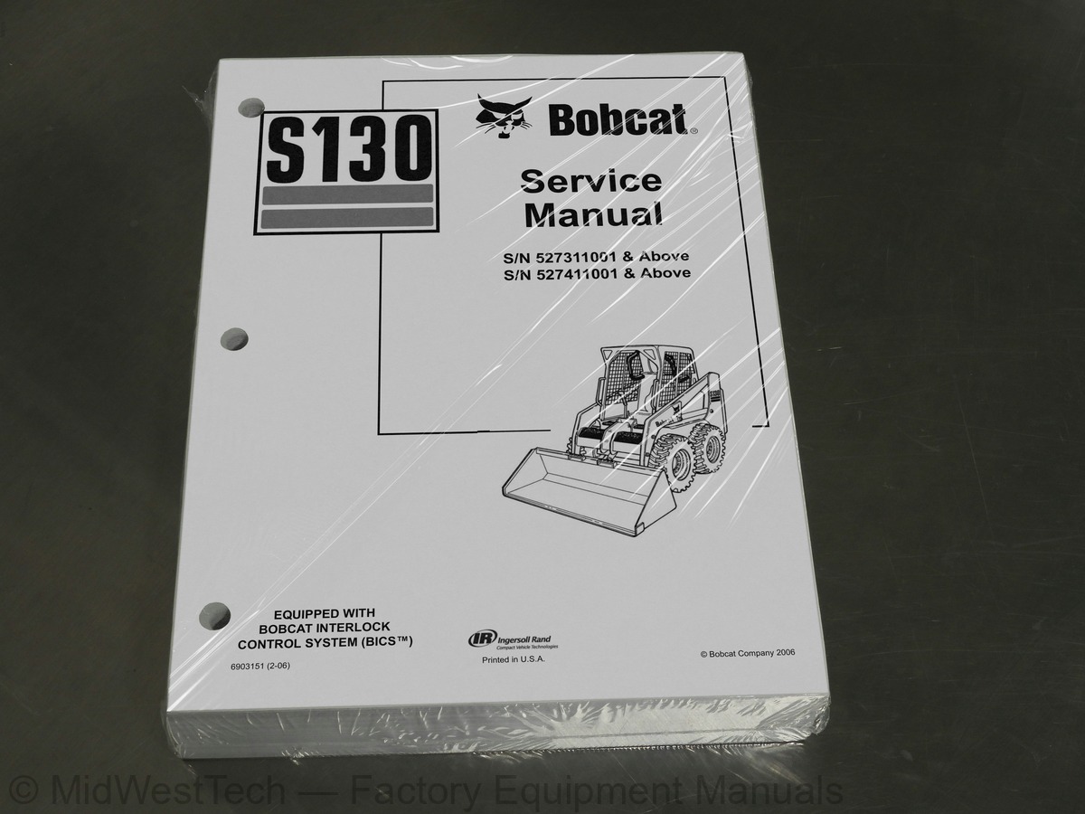
Bobcat S130 Skid Steer Loader Service Manual
612 pages · Publication 6903151_2_06
Added to your cart. View cart
- Models
- S130
- Serial coverage
- SN 527311001 & above, SN 527411001 & above
- Manual type
- Service Manual
- Pages
- 612
- Publication
- 6903151_2_06
- Condition
- Brand new
What's inside
From the manual's own table of contents: 21 sections, 521 entries. See sample pages (PDF, 443 KB)
FOREWORD7 topics
- SAFETY INSTRUCTIONS
- Fire Prevention
- SERIAL NUMBER LOCATIONS
- Loader Serial Number
- Engine Serial Number
- DELIVERY REPORT
- LOADER IDENTIFICATION
LIFTING AND BLOCKING THE LOADER56 topics
- Procedure
- LIFT ARM SUPPORT DEVICE
- Installing Lift Arm Support Device
- Removing The Lift Arm Support Device
- OPERATOR CAB
- Description
- Raising The Operator Cab
- Lowering The Operator Cab
- Emergency Exit
- TRANSPORTING THE BOBCAT LOADER
- Procedure
- TOWING THE LOADER
- Procedure
- REMOTE START
- Procedure
- SERVICE SCHEDULE
- Chart
- AIR CLEANER SERVICE
- Checking
- Replacing Filter Element(s)
- ENGINE COOLING SYSTEM
- Cleaning The Cooling System
- Checking The Coolant Level
- Replacing The Coolant
- FUEL SYSTEM
- Fuel Specifications
- Filling the Fuel Tank
- Fuel Filter
- Removing Air From The Fuel System
- ENGINE LUBRICATION SYSTEM
- Checking Engine Oil
- Oil Chart
- Replacing Oil And Filter
- HYDRAULIC/HYDROSTATIC SYSTEM
- Checking And Adding Fluid
- Replacing Hydraulic/Hydrostatic Filter
- Replacing Hydrostatic Motor Case Drain Filter(s)
- Replacing Hydraulic Fluid
- Breather Cap
- FINAL DRIVE TRANSMISSION (CHAINCASE)
- Checking And Adding Oil
- Removing The Oil
- FAN GEARBOX
- Checking And Maintaining
- BOB-TACH
- Inspection And Maintenance
- POWER BOB-TACH
- Inspection And Maintenance
- LUBRICATION OF THE BOBCAT LOADER
- Procedure
- TIRE MAINTENANCE
- Wheel Nuts
- Rotating
- Mounting
- SPARK ARRESTOR MUFFLER
- Servicing
HYDRAULIC/HYDROSTATIC SCHEMATICS99 topics
- HYDRAULIC SYSTEM INFORMATION
- Glossary Of Hydraulic/Hydrostatic Symbols
- Tighten Procedures
- Troubleshooting Chart
- CYLINDER (LIFT)
- Checking
- Removal And Installation
- Identification
- Disassembly
- Assembly
- CYLINDER (TILT)
- Checking
- Removal And Installation
- Rod End Pivot Pin Bushing And Seal Replacement
- Identification
- Disassembly
- Assembly
- CYLINDER (POWER BOB-TACH)
- Checking
- Removal And Installation
- Parts Identification
- Disassembly
- Assembly
- MAIN RELIEF VALVE
- Checking
- Adjustment
- Removal and Installation
- HYDRAULIC CONTROL VALVE (FOOT CONTROL)
- Removal And Installation
- Identification Chart
- BICS™ Valve, Lift Load Check Valve Removal And Installation
- Load Check Valve Removal And Installation (Tilt & Auxiliary)
- Anti-Cavitation Valve (Lift, Rod End)
- Port Relief/Anti-Cavitation Valve (Lift, Base End)
- Port Relief/Anti-Cavitation Valve (Tilt, Base End)
- Port Relief/Anti-Cavitation Valve (Tilt, Rod End)
- Port Relief Valve
- Plug Removal
- Rubber Boot Removal and Installation
- End Cap/Spool Lock Block Removal and Installation
- Lift Spool and Detent Removal and Installation
- Tilt Spool Removal and Installation
- Auxiliary Spool Removal And Installation
- Auxiliary Solenoid Disassembly and Assembly
- BICS™ Valve Solenoid Disassembly And Assembly
- BICS™ Valve, Lock Valve Removal And Installation
- BICS™ Valve, Check Valve Removal And Installation
- BICS™ Valve, Lift Arm By-Pass Orifice Disassembly And Assembly
- Main Relief Valve
- HYDRAULIC CONTROL VALVE (ADVANCED CONTROL SYSTEM) (ACS)
- Removal And Installation
- Actuator Removal And Installation (Out of Loader)
- Identification Chart (ACS)
- BICS™ Valve, Lift Load Check Valve Removal And Installation
- Load Check Valve Removal And Installation (Tilt & Auxiliary)
- Anti-Cavitation Valve (Lift, Rod End)
- Port Relief/Anti-Cavitation Valve (Lift, Base End)
- Port Relief/Anti-Cavitation Valve (Tilt, Base End)
- Port Relief/Anti-Cavitation Valve (Tilt, Rod End)
- Port Relief Valve
- Plug Removal
- End Cap Block Removal and Installation
- Lift Spool Removal and Installation
- Tilt Spool Removal and Installation
- Auxiliary Spool Removal And Installation
- Auxiliary Solenoid Disassembly and Assembly
- BICS™ Valve Solenoid Disassembly And Assembly
- BICS™ Valve, Lock Valve Removal And Installation
- BICS™ Valve, Check Valve Removal And Installation
- BICS™ Valve, Lift Arm By-Pass Orifice Disassembly And Assembly
- Main Relief Valve
- LIFT ARM BY-PASS CONTROL VALVE
- Inspecting
- Removal And Installation
- Disassembly And Assembly
- HYDRAULIC PUMP
- Check The Output Of The Hydraulic Pump Without Rear Auxiliary
- Check The Output Of The Hydraulic Pump With Rear Auxiliary
- Removal And Installation
- Identification
- Disassembly And Assembly
- HYDRAULIC/HYDROSTATIC FILTER
- Housing Removal And Installation
- HYDRAULIC FLUID RESERVOIR
- Removal And Installation
- BUCKET POSITION VALVE
- Solenoid Removal And Installation
- Solenoid Testing
- Removal And Installation
- Disassembly And Assembly
- REAR AUXILIARY DIVERTER VALVE
- Removal And Installation
- Disassembly And Assembly
- POWER BOB-TACH BLOCK
- Removal And Installation
- Disassembly And Assembly
- FRONT AUXILIARY HYDRAULIC COUPLER BLOCK
- Removal and Installation
- Disassembly And Assembly
HYDROSTATIC SYSTEM INFORMATION35 topics
- Troubleshooting Chart
- Replenishing Valve Function
- HYDROSTATIC MOTOR
- Removal And Installation
- Parts Identification
- Disassembly
- Assembly
- Carrier Shaft Seal Replacement
- Carrier Removal And Installation
- Carrier Parts Identification
- Carrier Disassembly
- Carrier Assembly
- CHARGE PRESSURE
- Sender Removal And Installation
- Checking Charge Pressure
- Adjusting
- HYDROSTATIC PUMP
- Replenishing/High Pressure Relief Valve
- Removal And Installation
- Parts Identification (Right Half)
- Parts Identification (Left Half)
- Hydraulic Pump Removal And Installation
- Pump Separation
- Disassembly
- Assembly
- DRIVE BELT
- Shield Removal And Installation
- Adjusting
- Drive Belt Replacement
- Tensioner Pulley Removal And Installation
- Tensioner Pulley Parts Identification
- Tensioner Pulley Disassembly
- Tensioner Pulley Assembly
- OIL COOLER
- Removal and Installation
BRAKE12 topics
- Disc Removal And Installation
- Switch Operated Parking Brake
- DRIVE COMPONENTS
- Axle Seal Removal And Installation
- Axle Sprocket And Bearings Removal And Installation
- Chain Removal And Installation
- CHAINCASE
- Checking And Adding Oil
- Removing The Oil
- Front Cover Removal And Installation
- Center Cover Removal And Installation
- Rear Cover Removal And Installation
SEAT BAR64 topics
- Removal And Installation
- Assembling Components
- Compression Spring Disassembly And Assembly
- Gas Cylinder Removal And Installation
- Gas Cylinder Disassembly
- Removal And Installation
- OPERATOR SEAT
- Removal And Installation
- Seat Belt Removal And Installation
- OPERATOR SEAT (SUSPENSION)
- Removal And Installation
- Slide Rail Removal And Installation
- Cushion Removal And Installation
- Back Removal And Installation
- Shock Removal And Installation
- 3-Point Seat Belt Removal And Installation
- Removal And Installation
- Bob-Tach Lever And Wedge
- Bob-Tach Stops
- Removal And Installation
- Power Bob-Tach Lever And Wedge
- LIFT ARM
- Removal And Installation
- REAR GRILL
- Removal And Installation
- REAR DOOR
- Removal And Installation
- Striker Removal and Installation
- Striker Disassembly and Assembly
- Door Latch and Catch Adjustment
- Latch Removal And Installation
- FUEL TANK
- Removal And Installation
- Fuel Level Sender
- CONTROL PEDALS
- Removal And Installation
- Pedal Adjustment
- Crossbar Linkage Removal And Installation
- Lift Foot Pedal Linkage Removal And Installation
- Tilt Foot Pedal Linkage Removal And Installation
- CONTROL PEDALS (ACS)
- Foot Sensor Removal And Installation
- Foot Pedal Removal And Installation
- Foot Pedal Linkage Disassembly And Assembly
- CONTROL PANEL
- Description
- Removal and Installation
- Shock Removal And Installation
- Shaft Removal And Installation
- Shaft Disassembly And Assembly
- Linkage Removal And Installation
- Pintle Arm Disassembly and Assembly
- Linkage Neutral Adjustment
- Linkage Travel Adjustment
- CONTROL HANDLE
- Control Lever Removal And Installation
- Control Rubber Boot Replacement
- CONTROL HANDLE (ADVANCED CONTROL SYSTEM) (ACS) SELECTABLE HAND/FOOT CONTROL
- Components Identification
- Handle Sensor Removal And Installation
- Control Handle Removal and Installation
- Control Handle Disassembly and Assembly
- Control Lever Removal and Installation
- Control Lever Boot
ELECTRICAL SCHEMATIC92 topics
- ELECTRICAL SYSTEM INFORMATION
- Troubleshooting Chart
- Description
- Relay Switch Location
- Fuse Location
- Solenoid Test
- BATTERY
- Removal And Installation
- Servicing
- Using A Booster Battery (Jump Starting)
- ALTERNATOR
- Adjusting The Alternator Belt
- Alternator Identification
- Charging System Check
- Alternator Voltage Test
- Low Voltage Test
- High Voltage Test
- Removal And Installation
- Rectifier Continuity (Diode) Test
- Alternator Regulator Test
- Disassembly
- Stator Continuity Test
- Stator Ground Test
- Rotor Continuity Test
- Rotor Ground Test
- Assembly
- STARTER
- Checking
- Removal And Installation
- Parts Identification
- Disassembly and Assembly
- Inspection And Repair
- No Load Test
- INSTRUMENT PANEL
- Left Panel
- Right Panel (Standard) (With Key Switch)
- Right Panel - (Deluxe) (With Keyless Start)
- Right Panel Setup Display Options (Deluxe)
- Option and Field Accessory Panels
- Removal And Installation
- Front Accessory Panel Removal And Installation
- LIGHTS
- Front Removal And Installation
- Rear Removal And Installation
- BOBCAT CONTROLLER
- Identification Chart
- Removal And Installation
- DIAGNOSTIC SERVICE CODES
- Display
- Number Codes List
- BICS™ SYSTEM
- Inspecting The BICS™ Controller (Engine STOPPED - Key ON)
- Inspecting Deactivation Of The Auxiliary Hydraulics System (Engine STOPPED - Key ON)
- Inspecting The Seat Bar Sensor (Engine RUNNING)
- Inspecting The Traction Lock (Engine RUNNING)
- Inspecting The Lift Arm By-Pass Control
- Additional Inspection For Loaders With Advanced Controls System (ACS) or Selectable Joystick Control (SJC)
- Troubleshooting Chart
- Troubleshooting Guide
- SEAT BAR SENSOR
- Troubleshooting Chart
- Test
- Removal And Installation
- BICS™ Circuit Test
- TRACTION LOCK
- Troubleshooting Chart
- Inspecting
- Solenoid Removal And Installation
- Guide Removal
- Guide Installation
- ADVANCED CONTROL SYSTEM (ACS) SELECTABLE HAND/FOOT CONTROL
- Components Identification
- Troubleshooting Guide
- Controller, Connector And Wire Identification
- ACS Controller Removal And Installation
- Handle Sensor Connector
- Switch Handle Removal
- Switch Handle Installation
- Actuators Disassembly And Assembly
- Handle Lock Solenoid Removal And Installation
- Handle Lock Solenoid Disassembly And Assembly
- Handle Lock Solenoid Connector
- Calibration Of The ACS System
- Switchable Hand/Foot Controls Calibration Procedure
- Foot Sensor Disassembly And Assembly
- Foot Sensor Connector
- Foot Lock Solenoid Removal And Installation
- Foot Lock Solenoid Connector
- ELECTRICAL/HYDRAULIC CONTROLS REFERENCE
- Controls Identification Chart
- FLYWHEEL RPM SENSOR
- Adjustment
TROUBLESHOOTING69 topics
- Chart
- ENGINE SPEED CONTROL
- Removal And Installation
- Disassembly
- MUFFLER
- Removal And Installation
- AIR CLEANER
- Removal And Installation
- RADIATOR
- Removal And Installation
- COOLING FAN
- Drive Tension Pulley Removal And Installation
- Gearbox/Blower Housing Removal And Installation
- Blower Housing Grill Removal And Installation
- Blower Disassembly And Assembly
- Gearbox Parts Identification
- Gearbox Disassembly
- Gearbox Assembly
- Gearbox Checking Backlash
- ENGINE COMPONENTS AND TESTING
- Compression Checking
- Glow Plugs Checking
- Glow Plugs Removal And Installation
- Fuel Shut-Off Solenoid, Checking
- Fuel Shut-Off Solenoid Removal And Installation
- Fuel Injection Pump Removal And Installation
- Timing The Injection Pump
- Fuel Injector Removal And Installation
- Checking Nozzle Injection Pressure
- Nozzle Spraying Condition
- Valve Seat Tightness
- Valve Clearance Adjustment
- Valve Timing, Checking
- ENGINE
- Removal And Installation
- Engine Mount Replacement
- FLYWHEEL AND HOUSING
- Flywheel Removal And Installation
- Ring Gear Removal And Installation
- Housing Removal And Installation
- RECONDITIONING THE ENGINE
- Cylinder Head Removal And Installation
- Cylinder Head Disassembly And Assembly
- Cylinder Head Servicing
- Cylinder Head Top Clearance
- Valve Guide Checking
- Reconditioning The Valve And Valve Seat
- Valve Spring
- Rocker Arm And Shaft Checking
- Timing Gearcase Cover Removal And Installation
- Idler Gear And Camshaft Removal And Installation
- Camshaft Servicing
- Idler Gear And Shaft Servicing
- Timing Gears Checking Backlash
- Fuel Camshaft Removal And Installation
- Fuel Camshaft Governor
- Crankshaft Gear Removal And Installation
- Oil Pump Removal And Installation
- Oil Pump Service
- Checking Engine Oil Pressure
- Valve Tappets
- Piston And Connecting Rod Removal And Installation
- Piston And Connecting Rod Servicing
- Connecting Rod Alignment
- Crankshaft And Bearings Removal And Installation
- Crankshaft And Bearings, Servicing
- Cylinder Bore, Checking
- Water Pump Removal And Installation
- Water Pump Disassembly And Assembly
COMPONENTS23 topics
- Identification
- REGULAR MAINTENANCE
- Filter Elements Removal And Installation
- BASIC TROUBLESHOOTING
- Cleaning The Heater Coil
- Checking The Electrical System
- Engine Coolant By-Passing The Heater Valve
- Heater Valve Not Opening Or Closing
- SYSTEM TROUBLESHOOTING CHART
- Blower Motor Does Not Operate
- Blower motor operators normally, but air flow is insufficient
- HEATER UNIT
- Removal And Installation
- Disassembly And Assembly
- HEATER COIL
- Removal And Installation
- HEATER FAN
- Removal And Installation
- Disassembly And Assembly
- Wire Connector Removal and Installation
- HEATER VALVE
- Removal and Installation
- Disassembly And Assembly
LOADER SPECIFICATIONS (S130)43 topics
- Machine Dimensions
- Performance
- Controls
- Engine
- Hydraulic System
- Electrical
- Drive System
- Capacities
- Tires
- ENGINE SPECIFICATIONS
- Fuel Injection Nozzles
- Fuel Injection Pump
- Cylinder Head
- Valves
- Valve Springs
- Valve Timing
- Rocker Arms
- Camshaft
- Tappet
- Cylinders
- Piston Rings
- Pistons
- Connecting Rod
- Oil Pump
- Crankshaft
- Timing Gear
- Thermostat
- TORQUE SPECIFICATIONS FOR BOLTS
- Torque For General SAE Bolts
- Torque For General Metric Bolts
- Torque For Kubota Metric Bolts
- HYDRAULIC CONNECTION SPECIFICATIONS
- O-ring Face Seal Connection
- Straight Thread O-ring Fitting
- Tubelines And Hoses
- Flare Fitting
- O-ring Flare Fitting
- Port Seal Fitting
- HYDRAULIC FLUID SPECIFICATIONS
- Specifications
- CONVERSIONS
- Decimal And Millimeter Equivalents
- U.S. To Metric Conversion
Inside this manual
Real pages from this service manual (612 pages). Open the sample pages (PDF, 442 KB)
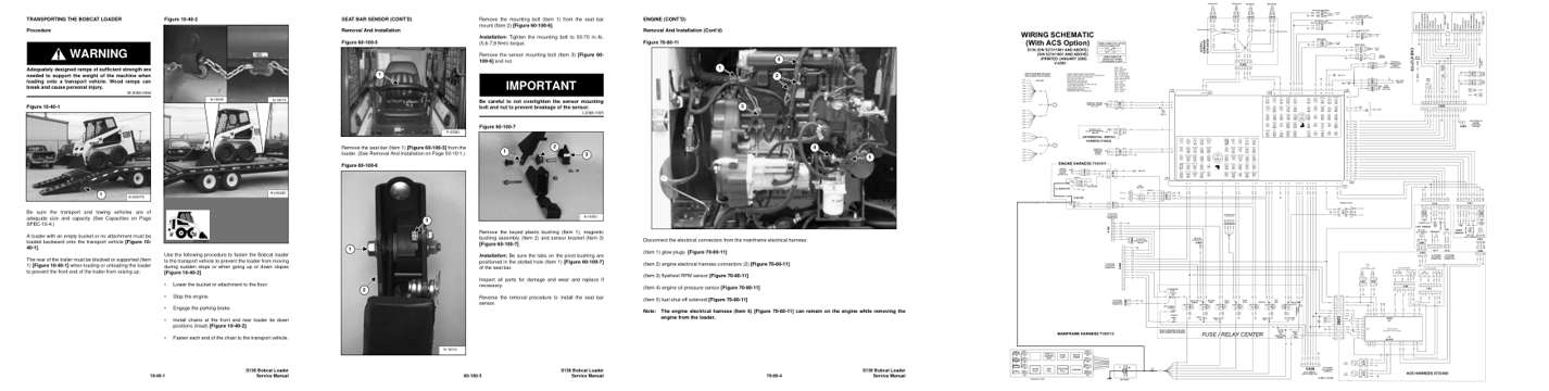
- Specifications, page 27: TRANSPORTING THE BOBCAT LOADER
- Repair procedure, page 441: SEAT BAR SENSOR (CONT’D)
- Diagram, page 522: ENGINE (CONT’D)
- Foldout diagram, page 380: SHUTOFF
Other manuals for this machine
Save 10% on 2 manuals, 15% on 3 or more. Other manuals for the S130 are listed below. Editions cover different serial number ranges: check the serial coverage and tick only the ones that match your machine.
Added to your cart. View cart
This is a service manual
Here's how it compares to the other manual types.
Service manual
Factory repair procedures and technical information such as specifications, troubleshooting, and wiring and hydraulic diagrams, for the models and systems the manual covers. See What's inside for its topics.
Operator's manual
Safe operation, controls, maintenance schedules, lubrication points, inspections, and basic checks. Repair procedures are in the service manual.
Parts manual
Illustrated diagrams with factory part numbers for identifying components and ordering parts. Repair procedures are in the service manual.
Engine service manuals are sometimes sold separately, since certain machine models were offered with more than one engine option.
What it's used for
Factory manual for in-house farm and construction shop use. Straightforward, complete, and easy to follow. It contains the OEM information dealership service departments and parts counters use to diagnose problems, identify components, and perform maintenance or repairs correctly.
Service shops and owner/operators who repair their own equipment
Identifying correct parts and seeing how assemblies come apart and go back together
Keeping equipment running with less downtime
Factory manual, 612 pages
Quantity one is the manual described above.
Fast free USA shipping
Ships in 1 business day.
60-day returns
Free if the mistake is ours. A manual ordered in error must come back unopened in its shrink-wrap; you pay return shipping and a 20% restocking fee applies. Return policy
Binder not included
Manuals over about 300 pages may need a standard 3-ring binder, which you can buy locally to keep the pages organized for shop use.
Other editions and similar models
Questions about model, serial number, engine coverage or contents? Contact us before purchasing and we'll help confirm it's the right manual. Please verify the manual type, machine model, serial number range and engine coverage before purchasing: manuals ordered in error carry a 20% restocking fee (return policy).