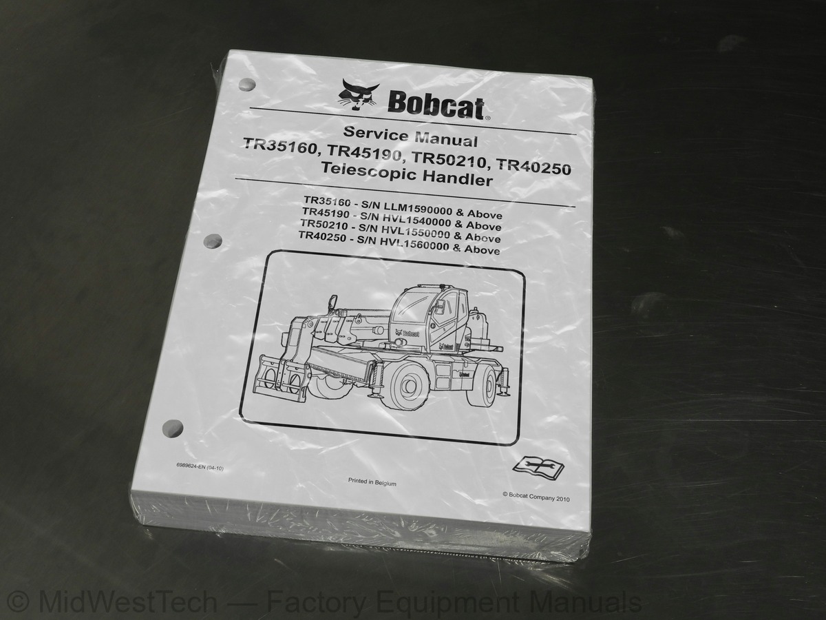
Bobcat TR35160, TR45190, TR50210, TR40250 Telescopic Handler Service Manual
695 pages · Publication 6989624_EN_04_10
Added to your cart. View cart
What's inside
From the manual's own table of contents: 16 sections, 502 entries. See sample pages (PDF, 564 KB)
FOREWORD17 topics
- SAFETY INSTRUCTIONS
- FIRE PREVENTION
- Maintenance
- Operation
- Electrical
- Hydraulic System
- Fueling
- Starting
- Spark Arrester Exhaust System
- Welding And Grinding
- Fire Extinguishers
- SERIAL NUMBER LOCATIONS
- Telescopic Handler Serial Numbers
- Engine Serial Number
- Other Serial Numbers
- DELIVERY REPORT
- BOBCAT TELESCOPIC HANDLER IDENTIFICATION
LIFTING AND BLOCKING THE TELESCOPIC HANDLER71 topics
- Procedure
- OPERATOR CAB
- Description
- Cab Door
- Cab Door Window
- Cab Rear Window
- Cab Light
- Cab Roof
- Cab Ventilation
- Rotating Beacon
- TRANSPORTING THE TELESCOPIC HANDLER
- Procedure
- TOWING THE TELESCOPIC HANDLER
- Procedure
- SERVICE SCHEDULE
- Chart
- Contents Of The Inspection Checkbook (logbook)
- AIR CLEANER SERVICE (TR35160)
- Cleaning The Air Filter
- Cleaning And Replacing Cartridges
- Cleaning The Primary Intake Duct
- ENGINE COOLING SYSTEM
- Cleaning The Cooling System
- Checking The Coolant Level
- Removing And Replacing The Coolant
- FUEL SYSTEM
- Fuel Specifications
- Biodiesel Blend Fuel
- Filling The Fuel Tank
- Fuel Filters (TR35160)
- Removing Air From The Fuel System
- Cleaning The Fuel Tank
- ENGINE LUBRICATION SYSTEM
- Checking And Adding Engine Oil (TR35160)
- Checking And Adding Engine Oil (TR45190, TR50210, TR40250)
- Engine Oil Chart
- Removing And Replacing Oil And Filter (TR35160)
- Removing And Replacing Oil And Filter (TR45190, TR50210, TR40250)
- HYDRAULIC / HYDROSTATIC SYSTEM
- Hydraulic / Hydrostatic Fluid Chart
- Checking And Adding Hydraulic / Hydrostatic Fluid
- Replacing Hydraulic / Hydrostatic Fluid And Filters
- AXLES (FRONT AND REAR)
- Checking And Adding Oil (Planetary Carrier)
- Removing And Replacing Oil (Planetary Carrier)
- Checking And Adding Oil (Front And Rear Differential)
- Removing And Replacing Oil (Front And Rear Differential)
- Checking And Adding Oil (Drive Box)
- Removing And Replacing Oil (Drive Box)
- LUBRICATING THE TELESCOPIC HANDLER
- Lubrication Locations
- Lubricating Telescopic Boom Wear Blocks
- Lubricating External Boom Chains
- TYRE MAINTENANCE
- Wheel Nuts
- Tyre Rotating
- Tyre Mounting
- Tyre Pressure
- ENGINE COVER
- Opening And Closing
- ANTI TIPPING DEVICE
- Description
- Main Work Data
- Complementary Work Data
- Attachment And Operating Mode
- Attachment Selection
- Unencoded Display Information
- Self-Diagnostics
- Anti Tipping Device Error Codes
- Remote Control Error Codes
- Diagnostics Displays
HYDRAULIC / HYDROSTATIC SCHEMATIC42 topics
- HYDRAULIC SYSTEM INFORMATION
- Troubleshooting Chart
- Tightening Procedures
- Hydraulic Component Pressures
- LIFT CYLINDER
- Removal And Installation
- Parts Identification
- Section View
- Parts Identification
- TILT CYLINDER
- Parts Identification
- DRIVE BOX
- Parts Identification
- Disassembly
- Assembly
- Parts Identification
- BRAKE AND GEAR VALVES
- Parts Identification
- STEERING MODE VALVE BLOCK
- Parts Identification
- STEERING VALVE
- Parts Identification
- Valve Section Identification
- Lifting Valve Section
- Upperstructure Swing Valve Section
- Telescoping Valve Section
- Tilting Valve Section
- Auxiliary Valve Section
- Inlet-outlet Valve Section
- End Housing
- HYDRAULIC CONTROL VALVE (TR35160)
- Valve Section Identification
- SWING MOTOR (TR35160)
- Parts Identification
- SWIVEL JOINT
- Parts Identification
- STABILISER EXTENSION CYLINDER (TR45190, TR50210, TR40250)
- Parts Identification
- REAR AXLE OSCILLATION LOCK CYLINDER
- Parts Identification
- STABILISER / LEVELING VALVE
- Parts Identification
HYDROSTATIC DRIVE MOTOR9 topics
- Parts Identification
- HYDROSTATIC PUMP
- Parts Identification
- HYDROSTATIC TRANSMISSION ADJUSTMENT
- Description
- Starting Adjustment
- Feeding Pressure
- Hydrostatic Pump Pressure
- Hydrostatic Motor Pressure
TROUBLESHOOTING59 topics
- Chart
- AXLE AND DIFFERENTIAL (FRONT)
- General Information
- Planetary Carrier Parts Identification
- Planetary Carrier Disassembly
- Steering Cylinder Parts Identification
- Steering Cylinder Removal
- Steering Cylinder Disassembly
- Steering Case Parts Identification
- Steering Case Disassembly
- Drive Axle Parts Identification
- Drive Axle Disassembly
- Brake System Parts Identification
- Brake System Disassembly
- Hydraulic Differential Lock Parts Identification
- Hydraulic Differential Lock Disassembly
- Differential Unit (Limited Slip) Parts Identification
- Differential Unit (Limited Slip) Disassembly
- Bevel Pinion Parts Identification
- Bevel Pinion Removal
- Bevel Pinion Installation And Adjustment
- Differential Unit (Limited Slip) Assembly
- Hydraulic Differential Lock Assembly
- Brake System Assembly
- Drive Axle Assembly
- Steering Case Assembly
- Steering Cylinder Assembly
- Steering Cylinder Installation
- Planetary Carrier Assembly
- Special Tools
- AXLE AND DIFFERENTIAL (REAR)
- General Information
- Planetary Carrier Parts Identification
- Planetary Carrier Disassembly
- Steering Cylinder Parts Identification
- Steering Cylinder Removal
- Steering Cylinder Disassembly
- Steering Case Parts Identification
- Steering Case Disassembly
- Drive Axle Parts Identification
- Drive Axle Disassembly
- Negative Brake Parts Identification
- Negative Brake Disassembly
- Hydraulic Differential Lock Parts Identification
- Hydraulic Differential Lock Disassembly
- Differential Unit (Limited Slip) Parts Identification
- Differential Unit (Limited Slip) Disassembly
- Bevel Pinion Parts Identification
- Bevel Pinion Removal
- Bevel Pinion Installation And Adjustment
- Differential Unit (Limited Slip) Assembly
- Hydraulic Differential Lock Assembly
- Negative Brake Assembly
- Drive Axle Assembly
- Steering Case Assembly
- Steering Cylinder Assembly
- Steering Cylinder Installation
- Planetary Carrier Assembly
- Special Tools
ELECTRICAL SCHEMATICS30 topics
- ELECTRICAL SYSTEM INFORMATION
- Troubleshooting Chart
- Fuse And Relay Location / Identification
- BATTERY
- Removal And Installation
- Battery Disconnect Switch
- Servicing
- Using A Booster Battery (Jump Starting)
- Battery Test
- Alternator Removal (Engines Without An Automatic Belt Tensioner)
- Alternator Installation (Engines Without An Automatic Belt Tensioner)
- Alternator Removal (Engines With An Automatic Belt Tensioner)
- Alternator Installation (Engines With An Automatic Belt Tensioner)
- Alternator Test
- Charging System Test
- Electric Starting Motor Removal
- Electric Starting Motor Installation
- Electric Starting System Test
- SENSORS AND SWITCHES
- Stabilisers extended and lowered (TR45190, TR50210, TR40250)
- Stabilisers lowered (TR35160)
- Upperstructure aligned with undercarriage
- Upperstructure rotated 174 (TR35160)
- Upperstructure slew lock inserted
- Axle oscillation lock range (12 )
- Boom raised / lowered and extended / retracted completely (TR45190, TR50210, TR40250)
- Boom raised / lowered completely (TR35160)
- MAN PLATFORM LOAD LIMITER CALIBRATION
- Description
- Procedure
ENGINE SERVICE204 topics
- Engine Errors
- Centre Indicator And Instrument Panel Pilot Lights
- Engine Over-Revs
- Engine Error Codes
- Error Menu
- Engine Error Codes List
- SENSORS AND ELECTRICAL COMPONENTS (TR45190, TR50210, TR40250)
- Sensor Locations
- Failure Of Sensors
- Programmable Monitoring System (PMS)
- Coolant Temperature Sensor
- Boost Pressure Sensor
- Inlet Air Temperature Sensor
- Fuel Pressure Sensor
- Crankshaft Position Sensor
- Position Sensor For The Fuel Injection Pump
- Engine Oil Pressure Sensor
- ENGINE COMPONENTS AND TESTING (TR45190, TR50210, TR40250)
- Fuel Priming Pump Removal (Electric Fuel Priming Pump)
- Fuel Priming Pump Installation (Electric Fuel Priming Pump)
- Fuel Priming Pump Removal (Manual Fuel Priming Pump)
- Fuel Priming Pump Installation (Manual Fuel Priming Pump)
- Fuel Filter Base Removal (Secondary Fuel Filter)
- Fuel Filter Base Installation (Secondary Fuel Filter)
- Fuel Transfer Pump Removal
- Fuel Transfer Pump Installation
- Fuel Injection Lines Removal
- Fuel Injection Lines Installation
- Fuel Manifold (Rail) Removal
- Fuel Manifold (Rail) Installation
- Fuel Injection Pump Removal
- Fuel Injection Pump Installation
- Fuel Injection Pump Gear Removal
- Fuel Injection Pump Gear Installation
- Position Sensor (Fuel Injection Pump) Removal
- Position Sensor (Fuel Injection Pump) Installation
- Fuel Pressure Sensor Removal
- Fuel Pressure Sensor Installation
- Boost Pressure Sensor Removal
- Boost Pressure Sensor Installation
- Electronic Unit Injector Removal
- Electronic Unit Injector Installation
- Electronic Unit Injector Installation (Alternative Installation Procedure)
- Lifter Group Removal
- Lifter Group Installation
- Fuel System Inspection
- Air In Fuel Test
- Finding Top Centre Position For No. 1 Piston
- Fuel Injection Timing Check
- Fuel Quality Test
- Fuel System Prime
- Compression Test
- Glow Plugs Removal
- Glow Plugs Installation
- Glow Plugs Test
- Flywheel Removal
- Flywheel Installation
- Flywheel Inspection
- Flywheel Housing Removal
- Flywheel Housing Installation
- Flywheel Housing Inspection
- Turbo Charger Removal
- Turbo Charger Installation
- Turbo Charger Inspection
- Wastegate Solenoid Removal
- Wastegate Solenoid Installation
- Exhaust Manifold Removal
- Exhaust Manifold Installation
- Exhaust Elbow Removal
- Exhaust Elbow Installation
- Valve Mechanism Cover Removal
- Valve Mechanism Cover Installation
- Valve Mechanism Cover Base Removal
- Valve Mechanism Cover Base Installation
- Cylinder Head Removal
- Cylinder Head Installation
- Cylinder Head Inspection
- Cylinder Block Inspection
- Rocker Shaft And Pushrod Removal
- Rocker Shaft And Pushrod Installation
- Rocker Shaft Disassembly
- Rocker Shaft Assembly
- Inlet And Exhaust Valves Removal
- Inlet And Exhaust Valves Installation
- Air Inlet And Exhaust System Inspection
- Engine Valve Lash Inspection / Adjustment
- Valve Depth Inspection
- Valve Guide Inspection
- Inlet And Exhaust Valve Springs Removal
- Inlet And Exhaust Valve Springs Installation
- Front Cover Removal
- Front Cover Installation
- Crankshaft Pulley Removal (Engines With An Automatic Belt Tensioner)
- Crankshaft Pulley Installation (Engines With An Automatic Belt Tensioner)
- Crankshaft Pulley Removal (Engines Without An Automatic Belt Tensioner)
- Crankshaft Pulley Installation (Engines Without An Automatic Belt Tensioner)
- Crankshaft Pulley Check
- Gear Group (Front) Removal
- Gear Group (Front) Installation
- Gear Group (Front) Timing
- Gear Group Inspection
- Idler Gear Removal (Standard Idler Gear)
- Idler Gear Installation (Standard Idler Gear)
- Idler Gear Removal (Heavy-Duty Idler Gear)
- Idler Gear Installation (Heavy-Duty Idler Gear)
- Housing (Front) Removal
- Housing (Front) Installation
- Accessory Drive Removal
- Accessory Drive Installation
- Crankcase Breather Removal (Filtered Breather)
- Crankcase Breather Installation (Filtered Breather)
- Crankcase Breather Removal (Unfiltered Breather)
- Crankcase Breather Installation (Unfiltered Breather)
- Camshaft Removal
- Camshaft Installation
- Camshaft Gear Removal
- Camshaft Gear Installation
- Camshaft Bearings Removal
- Camshaft Bearings Installation
- Pistons And Connecting Rods Removal
- Pistons And Connecting Rods Installation
- Pistons And Connecting Rods Disassembly
- Pistons And Connecting Rods Assembly
- Piston Ring Groove Inspection
- Connecting Rod Inspection
- Connecting Rod Bearings Removal (Connecting Rods In Position)
- Connecting Rod Bearings Installation (Connecting Rods In Position)
- Piston Height Inspection
- Crankshaft Main Bearings Removal (Crankshaft In Position)
- Crankshaft Main Bearings Installation (Crankshaft In Position)
- Crankshaft Removal
- Crankshaft Installation
- Crankshaft Timing Ring Removal
- Crankshaft Timing Ring Installation
- Crankshaft Gear Removal
- Crankshaft Gear Installation
- Bearing Clearance Check
- Crankshaft Position Sensor Removal
- Crankshaft Position Sensor Installation
- Crankshaft Rear Seal Removal
- Crankshaft Rear Seal Installation
- Crankshaft Wear Sleeve (Rear) Removal
- Crankshaft Wear Sleeve (Rear) Installation
- Crankshaft Front Seal Removal
- Crankshaft Front Seal Installation
- Crankshaft Wear Sleeve (Front) Removal
- Crankshaft Wear Sleeve (Front) Installation
- Water Temperature Regulator Removal
- Water Temperature Regulator Installation
- Water Temperature Regulator Test
- Coolant Temperature Sensor Removal
- Coolant Temperature Sensor Installation
- Cooling System Check
- Cooling System Inspection
- Water Pump Removal
- Water Pump Installation
- Water Pump Inspection
- Engine Oil Filter Base Removal
- Engine Oil Filter Base Installation
- Engine Oil Cooler Removal
- Engine Oil Cooler Installation
- Engine Oil Cooler Inspection
- Engine Oil Relief Valve Removal (Engines With A Balancer Unit)
- Engine Oil Relief Valve Installation (Engines With A Balancer Unit)
- Engine Oil Relief Valve Removal (Engines Without A Balancer Unit)
- Engine Oil Relief Valve Installation (Engines Without A Balancer Unit)
- Engine Oil Pump Removal (Engines Without A Balancer Unit)
- Engine Oil Pump Installation (Engines Without A Balancer Unit)
- Engine Oil Pump Inspection
- Engine Oil Pan Removal (Aluminium And Pressed Steel Oil Pans)
- Engine Oil Pan Installation (Aluminium And Pressed Steel Oil Pans)
- Engine Oil Pan Removal (Cast Iron Oil Pan)
- Engine Oil Pan Installation (Cast Iron Oil Pan)
- Engine Oil Pressure Sensor Removal
- Engine Oil Pressure Sensor Installation
- Engine Oil Pressure Test
- Excessive Engine Oil Consumption Inspection
- Increased Engine Oil Temperature Inspection
- Excessive Bearing Wear Inspection
- Balancer Removal
- Balancer Installation
- Balancer Disassembly
- Balancer Assembly
- Piston Cooling Jets Removal
- Piston Cooling Jets Installation
- Inlet Air Temperature Sensor Removal
- Inlet Air Temperature Sensor Installation
- V-belts Removal (Engines Without An Automatic Belt Tensioner)
- V-belts Installation (Engines Without An Automatic Belt Tensioner)
- V-belt Test
- Alternator Belt Removal (Engines With An Automatic Belt Tensioner)
- Alternator Belt Installation (Engines With An Automatic Belt Tensioner)
- Fan Removal
- Fan Installation
- Fan Drive Removal
- Fan Drive Installation
- Electronic Control Module Removal
- Electronic Control Module Installation
- ECM Mounting Bracket Removal
- ECM Mounting Bracket Installation
- Air Compressor Removal
- Air Compressor Installation
- Vacuum Pump Removal
- Vacuum Pump Installation
(TR35160, TR45190, TR50210, TR40250) TELESCOPIC HANDLER SPECIFICATIONS54 topics
- Machine Dimensions
- Performance
- Engine
- Transmission
- Hydraulic System
- Differential Axles
- Capacities
- Tyres
- Environmental
- General
- Fuel Transfer Pump
- Electric Fuel Priming Pump
- Lifter Group
- Rocker Shaft
- Cylinder Head Valves
- Cylinder Head
- Turbo Charger
- Camshaft
- Camshaft Bearings
- Engine Oil Pump - Engines With Balancer Group
- Engine Oil Pressure
- Engine Oil Bypass Valve - Installed In The Oil Pump
- Engine Oil Bypass Valve - Installed In The Balancer
- Water Temperature Regulator And Housing
- Cylinder Block
- Crankshaft
- Crankshaft Journals
- Connecting Rod Bearing Journal
- Main Bearing Journal
- Shell For The Main Bearings
- Connecting Rod
- Piston And Rings - Rings
- Piston And Rings - Piston
- Piston And Rings - Oversize Piston
- Piston Cooling Jet Alignment
- Front Housing And Covers
- Gear Group (Front)
- Flywheel
- Belt Tension Chart
- Alternator
- Engine Torque Values
- TORQUE SPECIFICATIONS FOR BOLTS
- Torque for General SAE Bolts
- Torque For General Metric Bolts
- HYDRAULIC CONNECTION SPECIFICATIONS
- O-ring Face Seal Connection
- Straight Thread O-ring Fitting
- Tubelines And Hoses
- Flare Fitting
- O-ring Flare Fitting
- Port Seal Fitting
- CONVERSIONS
- Decimal And Millimeter Equivalents
- U.S. To Metric Conversion Chart
Inside this manual
Real pages from this service manual (695 pages). Open the sample pages (PDF, 563 KB)

- Troubleshooting, page 90: ANTI TIPPING DEVICE (CONT’D)
- Diagram, page 550: RECONDITIONING THE ENGINE (TR45190, TR50210,
- Specifications, page 670: (TR35160, TR45190, TR50210, TR40250) TELESCOPIC HANDLER SPECIFICATIONS (CONT’D)
- Color page, page 98
- Color page, page 375: Anti Tipping Device - Inputs And Outputs
- Foldout diagram, page 408: Valid certified
Other manuals for this machine
Save 10% on 2 manuals, 15% on 3 or more. Other manuals for the TR35160, TR45190, TR50210, TR40250 are listed below. Editions cover different serial number ranges: check the serial coverage and tick only the ones that match your machine.
Added to your cart. View cart
This is a service manual
Here's how it compares to the other manual types.
Service manual
Factory repair procedures and technical information such as specifications, troubleshooting, and wiring and hydraulic diagrams, for the models and systems the manual covers. See What's inside for its topics.
Operator's manual
Safe operation, controls, maintenance schedules, lubrication points, inspections, and basic checks. Repair procedures are in the service manual.
Parts manual
Illustrated diagrams with factory part numbers for identifying components and ordering parts. Repair procedures are in the service manual.
Engine service manuals are sometimes sold separately, since certain machine models were offered with more than one engine option.
What it's used for
Factory manual for in-house farm and construction shop use. Straightforward, complete, and easy to follow. It contains the OEM information dealership service departments and parts counters use to diagnose problems, identify components, and perform maintenance or repairs correctly.
Service shops and owner/operators who repair their own equipment
Identifying correct parts and seeing how assemblies come apart and go back together
Keeping equipment running with less downtime
Factory manual, 695 pages
Quantity one is the manual described above.
Fast free USA shipping
Ships in 1 business day.
60-day returns
Free if the mistake is ours. A manual ordered in error must come back unopened in its shrink-wrap; you pay return shipping and a 20% restocking fee applies. Return policy
Binder not included
Manuals over about 300 pages may need a standard 3-ring binder, which you can buy locally to keep the pages organized for shop use.
Questions about model, serial number, engine coverage or contents? Contact us before purchasing and we'll help confirm it's the right manual. Please verify the manual type, machine model, serial number range and engine coverage before purchasing: manuals ordered in error carry a 20% restocking fee (return policy).