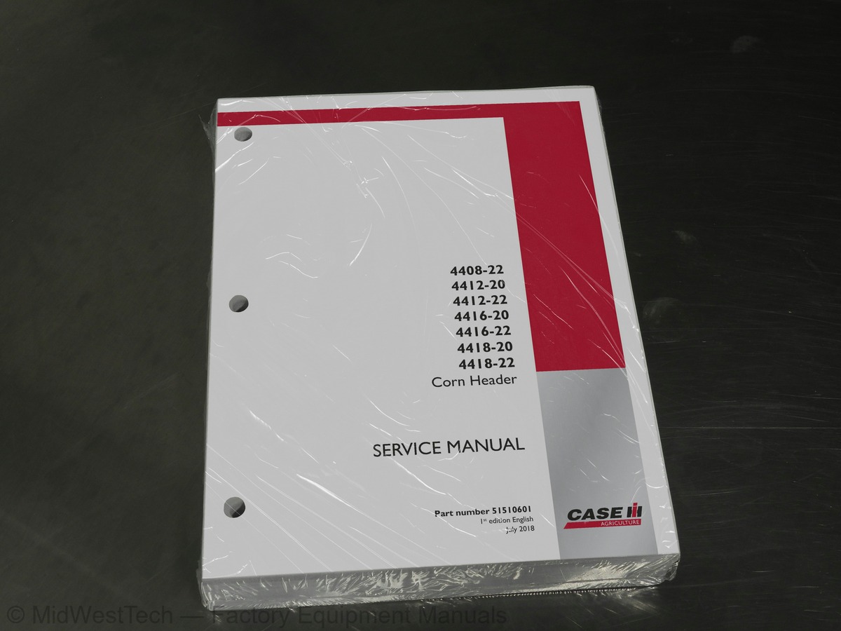
Case 4408-224412-20, 4412-22, 4416-20, 4416-22, 4418-20, 4418-22 Corn Header Service Manual
539 pages · Publication 51510601
Added to your cart. View cart
- Models
- 4408-224412-20, 4412-22, 4416-20, 4416-22, 4418-20, 4418-22
- Manual type
- Service Manual
- Pages
- 539
- Publication
- 51510601
- Condition
- Brand new
What's inside
From the manual's own table of contents: 157 topics. See sample pages (PDF, 530 KB)
- Hydraulic systems
- Deck plate hydraulic system
- Head and header hydraulic drive
- Electrical systems
- Electrical system
- Harnesses and connectors
- External lighting
- Feeding control system
- Header height control
- Precision farming system
- Chopper slip clutch monitoring system
- Attachments/Headers
- Attachment/Header support and drives
- Attachment/Header feed auger
- Attachment/Header frame
- Corn header shields and guards
- Corn header feed chain and rollers
- Corn header feeder structure
- Corn header structure
- Header drive
- Rotating dividers
- Stalk choppers
- Row-independent header gearboxes
- Lubrication system
Show all 157 topics
- Foreword - Important notice regarding equipment servicing
- Personal safety
- Safety rules
- Safety rules - Ecology and the environment
- Safety signs
- Basic instructions - Shop and assembly
- Torque - Minimum tightening torques for normal assembly
- Torque - Standard torque data for hydraulics
- Hydraulic contamination
- Basic instructions - Chain Wear Tables - Roller Chains
- Attachments/Headers - Basic instructions
- General specification
- Capacities
- Product identification
- Product overview - Machine orientation
- General specification - Deck plate cylinder
- General specification - Auger divider motor
- Hydraulic schematic frame 01
- Hydraulic schematic frame 02 - Auger divider Motors
- Hydraulic schematic frame 03 - Deck plate - open
- Hydraulic schematic frame 04 - Deck plate - close
- Component localization - Rigid hydraulic systems
- Overview
- Remove control valve block
- Install control valve block
- Remove
- Install
- Exploded view
- Rotating dividers - Remove - Motor
- Rotating dividers - Disassemble - Motor
- Rotating dividers - Assemble - Motor
- Rotating dividers - Install - Motor
- Electrical schematic sheet 03 - CORN HEAD ELECTRICAL
- Electrical schematic sheet 04 - SLIP CLUTCH AND ICM
- Electrical schematic sheet 05 - ADD ON ALARM HARNESSES
- Component diagram 00 Connector X-4008A1 to X-4008A2
- Component diagram 03 Connector X-030 to X-039
- Component diagram 46 Connector X-460 to X-469
- Component diagram 47 Connector X-470 to X-479
- Component diagram 98 Connector X-980 to X-989
- Component diagram 99 Connector X-4000 to X-4019
- Component diagram 100 Connector X-1000 to X-1009
- Component diagram 300 Connector X-3000 to X-3009
- Component diagram 311 Connector X-3110 to X-3119
- Component diagram 331 Connector X-3310 to X-3319
- Component diagram 380 Connector X-3800 to X-3809
- ECU description
- Sensor description
- Lamp description
- Fuse description
- Speaker description
- Switch description
- Component identification - Rigid electrical systems
- Repair
- Testing - Left-Hand (LH) Flasher Light (LT) Short circuit
- Header type module - Technical Data
- Header type module - Overview
- Header type module - Remove
- Header type module - Install
- Header type module - Testing
- Header type module - Testing - Shorted to high source
- Header type module - Testing - Data incorrect
- Technical Data - Header height
- Overview - Automatic Head Height Control (AHHC)
- Dynamic description - Automatic Head Height Control (AHHC)
- Technical Data - Row guidance sensors
- Overview - Automatic Row Guidance System
- Dynamic description - Automatic Row Guidance Sensors
- Remove - Automatic Row Guidance Sensors
- Install - Automatic Row Guidance Sensors
- Testing - Shorted to low source (left row guidance sensor)
- Testing - Shorted to high source (left row guidance sensor)
- Testing - Shorted to low source (right row guidance sensor)
- Testing - Shorted to high source (right row guidance sensor)
- Technical Data - Knock sensor
- Dynamic description
- Testing - Shorted to high source
- Testing - Shorted to low source
- Testing - Sensor not detected (LH Knock Sensor)
- Testing - Sensor not detected (Center Knock Sensor)
- Testing - Sensor not detected (RH Knock Sensor)
- Main gearbox and drive - Mechanical schema - Drive line schematics
- Exploded view - Main PTO
- Exploded view - Secondary PTO
- Intermediate shaft - Remove
- Intermediate shaft - Install
- Quick-connect lock - Disassemble
- Quick-connect lock - Assemble
- Driven sprocket - Remove - Auger sprocket
- Central section - Disassemble - Split augers only
- Central section - Assemble - Split augers only
- Driven sprocket - Install - Auger sprocket
- Adjust
- Drive sprocket - Remove
- Drive sprocket - Install
- Remove idler sprocket
- Install idler sprocket
- Snapper unit - Remove
- Disassemble
- Snapper unit - Assemble
- Assemble
- Row-independent header frame - Install
- Adjust deck plates
- Exploded view - Row unit
- Remove - Row unit drive
- Visual inspection - Row unit drive
- Check - Row unit drive torque slippage
- Disassemble - Row unit drive
- Inspect - Row unit drive internal components
- Assemble - Row unit drive
- Install - Row unit drive
- Exploded view - Stalk chopper knives
- Exploded view - Stalk chopper gearbox
- Sectional view - Stalk chopper gearbox
- Remove hex shaft
- Install hex shaft
- Remove - Stalk chopper gearbox
- Disassemble - Stalk chopper gearbox
- Assemble - Stalk chopper gearbox
- Install - Stalk chopper gearbox
- Gearbox housing - Special tools
- Timing adjust
- Remove backsheet gearbox - eight row and twelve row headers
- Install backsheet gearbox - eight row and twelve row headers
- Remove backsheet gearbox - sixteen row and eighteen row headers
- Install backsheet gearbox - sixteen row and eighteen row headers
- Remove row unit lineshaft gearbox - eight row and twelve row headers
- Install row unit lineshaft gearbox - eight row and twelve row headers
- Remove row unit lineshaft gearbox - sixteen row and eighteen row headers
- Install row unit lineshaft gearbox - sixteen row and eighteen row headers
- Remove chopper lineshaft gearbox - eight row and twelve row headers
- Install chopper lineshaft gearbox - eight row and twelve row headers
- Remove chopper lineshaft gearbox - sixteen row and eighteen row headers
Inside this manual
Real pages from this service manual (539 pages). Open the sample pages (PDF, 530 KB)

- Specifications, page 56: Hydraulic systems - Hydraulic systems
- Diagram, page 136: Electrical systems - Harnesses and connectors
- Repair procedure, page 520: Attachments/Headers - Row-independent header gearboxes
- Color page, page 28: INTRODUCTION
- Color page, page 305: Attachments/Headers - Attachment/Header support and drives
- Foldout diagram (color), page 108: Electrical systems - Harnesses and connectors
This is a service manual
Here's how it compares to the other manual types.
Service manual
Factory repair procedures and technical information such as specifications, troubleshooting, and wiring and hydraulic diagrams, for the models and systems the manual covers. See What's inside for its topics.
Operator's manual
Safe operation, controls, maintenance schedules, lubrication points, inspections, and basic checks. Repair procedures are in the service manual.
Parts manual
Illustrated diagrams with factory part numbers for identifying components and ordering parts. Repair procedures are in the service manual.
Engine service manuals are sometimes sold separately, since certain machine models were offered with more than one engine option.
What it's used for
Factory manual for in-house farm and construction shop use. Straightforward, complete, and easy to follow. It contains the OEM information dealership service departments and parts counters use to diagnose problems, identify components, and perform maintenance or repairs correctly.
Service shops and owner/operators who repair their own equipment
Identifying correct parts and seeing how assemblies come apart and go back together
Keeping equipment running with less downtime
Factory manual, 539 pages
Quantity one is the manual described above.
Fast free USA shipping
Ships in 1 business day.
60-day returns
Free if the mistake is ours. A manual ordered in error must come back unopened in its shrink-wrap; you pay return shipping and a 20% restocking fee applies. Return policy
Binder not included
Manuals over about 300 pages may need a standard 3-ring binder, which you can buy locally to keep the pages organized for shop use.
Questions about model, serial number, engine coverage or contents? Contact us before purchasing and we'll help confirm it's the right manual. Please verify the manual type, machine model, serial number range and engine coverage before purchasing: manuals ordered in error carry a 20% restocking fee (return policy).