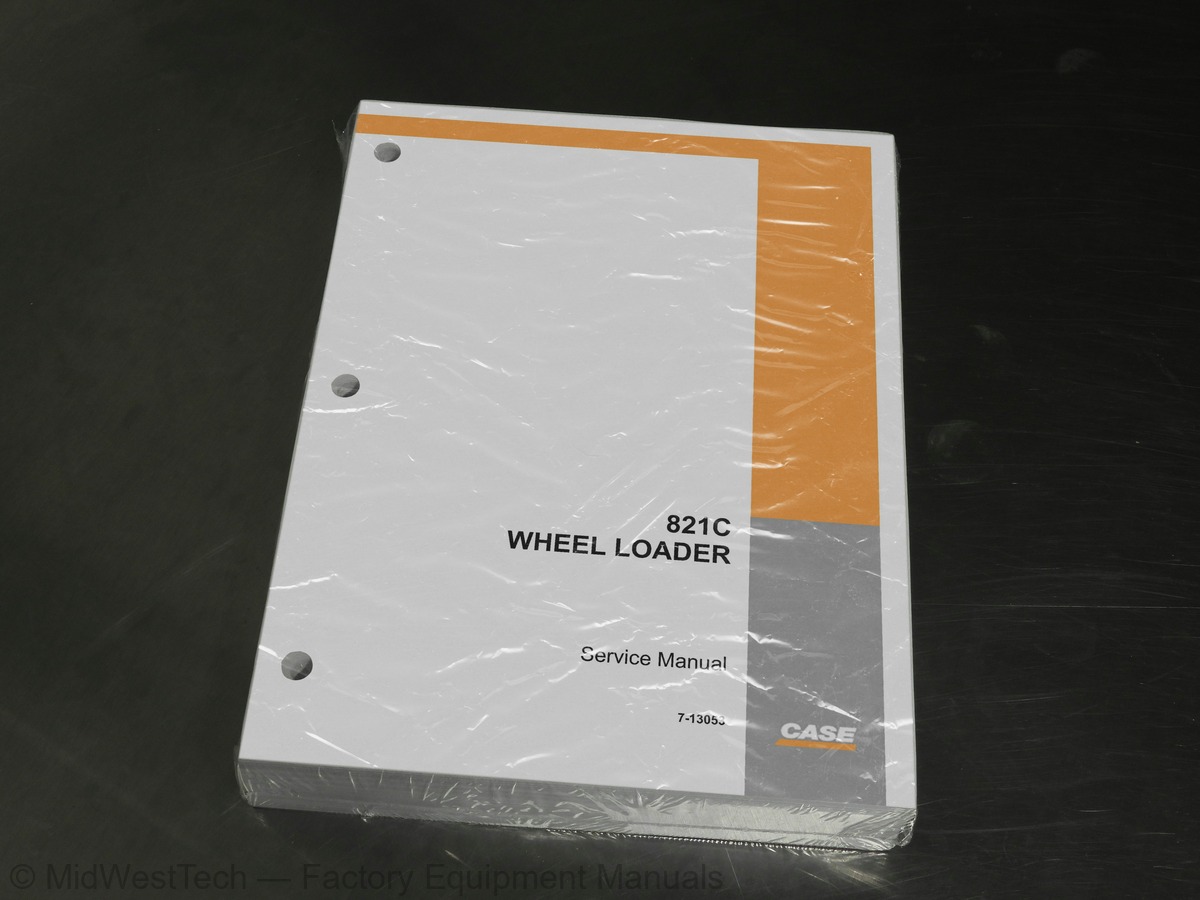
Case 821C Wheel Loader Service Manual
717 pages · Publication 7-13053
Added to your cart. View cart
- Models
- 821C
- Manual type
- Service Manual
- Pages
- 717
- Publication
- 7-13053
- Condition
- Brand new
What's inside
From the manual's own table of contents: 168 topics. See sample pages (PDF, 586 KB)
- CAPACITIES AND LUBRICANTS
- ENGINE OIL RECOMMENDATIONS
- DIESEL FUEL
- MAINTENANCE SCHEDULE
- Limited slip additive
- SPECIFICATIONS
- GRAPHIC SYMBOLS
- CIRCUIT DIAGRAM LEGEND, COLOR ABBREVIATIONS, AND NOTES
- HOW TO USE THIS SECTION
- IGNITION SWITCH AND RELAYS
- Batteries
- Master Disconnect Switch
- Fuel Shutoff Solenoid
- Alternator
- Starter Motor
- Start Relay
- Fuel Relay
- Cold Start Temperature Switch
- Ether Solenoid
- Ether Start Relay
- Ether Start Switch
- Neutral Start Relay
- Ignition Switch
- Ignition Relay #1
Show all 168 topics
- MODULE
- Ignition Relay #2
- Accessory Relay #3
- Voltmeter Relay #12
- Time Delay Module
- SHIFTER, DIAGNOSTIC CONNECTOR, AND BACK-UP ALARM
- Output Speed Sensor
- Engine Speed Sensor
- Intermediate Speed Sensor
- Turbine Speed Sensor
- Filter Maintenance Switch
- Torque Converter Output Temperature Sender
- Transmission Solenoid Valve and Temperature Sensors
- Transmission Electronic Control Module
- Transmission Shifter
- Diagnostic Connector
- Transmission Kick-down Switch (Located In Hydraulic Controller)
- Transmission Auto Switch
- Declutch Switch
- Declutch Brake Switch
- Back-up Alarm Relay #7
- Back-up Alarm Disable Switch
- Back-up Alarm
- SWITCH, INSTRUMENT CLUSTER, PILOT CONTROL SWITCH, AND UP/DOWN COUNT SWITCH
- Brake Warning Pressure Switch
- Coolant Level Sender
- Fuel Level Sender
- Hydraulic Oil Temperature Sender
- INFORMATION AND DIAGNOSTIC CENTER
- Self-Test
- Power Circuit Test
- Indicators and Gauges
- Stop Master Indicator (Red)
- Caution Master Indicator (Yellow)
- Beacon Indicator
- Pilot Control
- Low Coolant Indicator
- Brake Pressure Indicator
- Secondary Steering Indicator (If equipped)
- Parking Brake Indicator
- Air Conditioning Indicator
- Air Filter Indicator
- Hydraulic Oil Filter Indicator
- Transmission Oil Filter Indicator (Not applicable to 621C)
- Transmission Oil Temperature Gauge
- Hydraulic Oil Temperature Gauge
- Voltmeter Gauge
- Fuel Level Gauge
- Engine Oil Pressure Gauge
- Engine Coolant Temperature
- Service Indicator Icon
- WARNING DISPLAYS
- Critical Warning Displays
- Non-Critical Warning Displays
- Hourmeter
- Tachometer
- Speedometer
- Engine Oil Pressure
- Fuel Level
- Transmission Oil Temperature
- Hydraulic Oil Temperature
- Voltmeter
- Transmission Display
- Direction Selected
- Requested Gear
- Actual Gear
- Transmission Mode (Automatic or Manual)
- SETTINGS, DIAGNOSTICS, AND FAULT CODES
- Programming the Information Center
- Manual Scrolling Gauge Displays (01, 02, or 05
- Automatically Scrolling Gauge Displays (03 or 04)
- Individual Function Display
- Testing the Park Brake
- Transmission Clutch Calibration
- Setting Display Center Lighting
- Voltmeter at Key ON Position
- Alarm Check
- Coolant Level Check
- SPECIAL TOOLS
- TRANSMISSION OPERATION
- General
- Transmission ECM
- Gear Selections
- Automatic/Manual Modes
- Downshift Button
- Brake Pedal Transmission Declutch
- TRANSMISSION PRESSURE TEST POINTS DIAGRAM
- CHART FOR RECORDING PRESSURE READINGS
- PRESSURE TEST RESULTS
- All or Most Pressures Low and/or Flow Test Low
- Some Pressures Low
- Not Enough Power
- Machine Stops or Hesitates While Shifting - Intermittent
- CONVERTER OUT PRESSURE CHECK
- Test Equipment Required
- Test Procedure
- LUBRICATION PRESSURE CHECK
- FLOWMETER TEST
- Flowmeter Test Procedure
- CONSUMPTION TEST PROCEEDURE
- TRANSMISSION OVERHEATING
- ERROR CODES
- TRANSMISSION SHIFTER LOGIC INFORMATION
- RELATIONSHIP BETWEEN TRANSMISSION ECM, VALVES, AND CLUTCHES
- TRANSMISSION ELECTRICAL SCHEMATIC
- SPECIAL TORQUES
- DISASSEMBLY
- ASSEMBLY
- TIRE PRESSURE
- CHANGING TIRES
- INSTALLING A WHEEL
- WHEEL NUTS
- Torque Specification
- TROUBLESHOOTING PROCEDURE
- Problems in All Circuits - See the following pages for other circuits
- Problem in All Loader Circuits
- Problem in the Braking Circuit
- Problem in a Single Loader Circuit
- Problem in the Steering Circuit
- Testing the Hydraulic Pump
- Test No. 1 - Primary Pump Output Test
- Test No. 2 - Secondary Pump Output Test
- Testing and Adjusting the Main Relief Valve
- Pressure Check
- Adjustment
- Testing and Adjusting the Combination Valve
- Leak Test
- Testing the Control Pressure at the Ends of the Spools in the Loader Control Valve
- Testing and Adjusting the Circuit Relief Valves
- Testing and Adjusting the Pressure for the Unloader Valve
- HYDRAULIC COMPONENT LOCATIONS
- 821C HYDRAULIC SCHEMATIC
- SPECIFICATION
- HYDRAULIC PUMP
- Inspection
- SEPARATING THE VALVE SECTIONS
- BUCKET AND AUXILIARY SECTIONS
- LIFT SECTION
- REGENERATION VALVE
- MAIN RELIEF VALVE
- CIRCUIT RELIEF VALVE
- CIRCUIT RELIEF AND ANTICAVITATION VALVE
- CHARGING THE ACCUMULATOR WITH NITROGEN
- ACCUMULATOR
Inside this manual
Real pages from this service manual (717 pages). Open the sample pages (PDF, 585 KB)
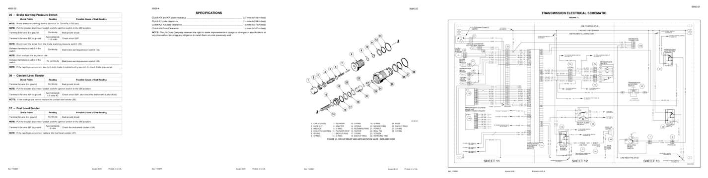
- Troubleshooting, page 75: 35 – Brake Warning Pressure Switch
- Specifications, page 295: SPECIFICATIONS
- Diagram, page 526: FIGURE 12 - CIRCUIT RELIEF AND ANTICAVITATION VALVE - EXPLODED VIEW
- Foldout diagram, page 290: Issued 4-00
Other manuals for this machine
Save 10% on 2 manuals, 15% on 3 or more. Other manuals for the 821C are listed below. Editions cover different serial number ranges: check the serial coverage and tick only the ones that match your machine.
Added to your cart. View cart
This is a service manual
Here's how it compares to the other manual types.
Service manual
Factory repair procedures and technical information such as specifications, troubleshooting, and wiring and hydraulic diagrams, for the models and systems the manual covers. See What's inside for its topics.
Operator's manual
Safe operation, controls, maintenance schedules, lubrication points, inspections, and basic checks. Repair procedures are in the service manual.
Parts manual
Illustrated diagrams with factory part numbers for identifying components and ordering parts. Repair procedures are in the service manual.
Engine service manuals are sometimes sold separately, since certain machine models were offered with more than one engine option.
What it's used for
Factory manual for in-house farm and construction shop use. Straightforward, complete, and easy to follow. It contains the OEM information dealership service departments and parts counters use to diagnose problems, identify components, and perform maintenance or repairs correctly.
Service shops and owner/operators who repair their own equipment
Identifying correct parts and seeing how assemblies come apart and go back together
Keeping equipment running with less downtime
Factory manual, 717 pages
Quantity one is the manual described above.
Fast free USA shipping
Ships in 1 business day.
60-day returns
Free if the mistake is ours. A manual ordered in error must come back unopened in its shrink-wrap; you pay return shipping and a 20% restocking fee applies. Return policy
Binder not included
Manuals over about 300 pages may need a standard 3-ring binder, which you can buy locally to keep the pages organized for shop use.
Other editions and similar models
Questions about model, serial number, engine coverage or contents? Contact us before purchasing and we'll help confirm it's the right manual. Please verify the manual type, machine model, serial number range and engine coverage before purchasing: manuals ordered in error carry a 20% restocking fee (return policy).