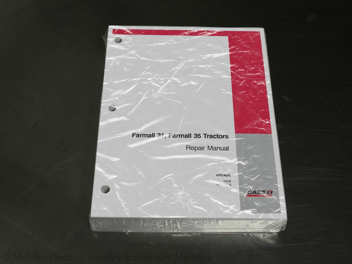
Case Farmall 31, 35 Tractor Service Manual
769 pages · Publication 84132127
Added to your cart. View cart
- Models
- Farmall 31, 35
- Manual type
- Service Manual
- Pages
- 769
- Publication
- 84132127
- Condition
- Brand new
What's inside
From the manual's own table of contents: 90 sections, 555 entries. See sample pages (PDF, 297 KB)
SECTION 41 - STEERING SYSTEMS1 topic
- Operating the PTO
Ecology and the Environment1 topic
- Helpful Hints 2.0.0.0
Lubrication and Maintenance2 topics
- Lubrication 2.0.0
- Cooling System All Models
Special TOOls 2.1.61 topic
- Compression Test and Tools
Description of Operation - General Information2 topics
- Cylinder Head and Valve Train Components
- Cylinder Block Assembly
Overhaul 063 topics
- Engine 2.0
- Preparation
- Fuel Injector and Glow Plug
- Removal
- Oil Pressure SWitch 2.1
- Removal
- Temperature Sending Switch and Alternator
- Removal
- Fan, Water Pump and External Oil Tube
- Removal
- Cylinder Head 0.0
- Removal
- Valve Tappet
- Fuel Shutoff Solenoid
- Removal
- Timing Gear Cover 0.0
- Removal
- Flywheel
- Removal 0.0
- Backplate and Oil Seal
- Removal
- Front Crankshaft Gear
- Inspection and Replacement
- Cylinder BIOCK
- Inspection
- Piston RINGS
- Disassembly and Inspection
- Connecting Rods
- Pin to Bushing Clearance
- Connecting Rod Bearing Oil Clearance Check
- Pistons, Rings and Connecting Rod
- ASSEMDIy 2
- Removal and Inspection
- Inspection
- Crankshaft Bearing (Bushing)
- INSpection
- Replacement
- Crankshaft Front Gear, Main Bearings and Thrust Washers
- ASSOEMDIy 2.6
- Camshaft 0.2
- Disassembly
- INSPeECtiON . 6
- ASSOMDIY 2
- Installation 6.0
- Pistons and Connecting Rods
- Oil Suction Pipe and Suction Strainer
- Installation 0.0
- Installation
- Power Steering PUMP
- Installation 0.0
- Valve Clearance Adjustment
- Head Cover
- Installation
- Water Pump and Cooling Fan
- External Oil Tube 2.0.0.0
- Installation
- Fuel Injector 2.0.0
- Installation 0.0
- Fuel Piping
- Installation
- Alternator and Temperature Sender Switch
- Exhaust Manifold
- Installation
Description of Operation - Engine Lubrication System13 topics
- Construction and Function
- Maintenance
- Removal
- INSPECTION 00
- Installation and Adjustment
- Engine Oil Pressure Check
- Oil Pressure Relief Valve
- Removal
- Installation 0.0
- Maintenance
- Installation
- Thermostat 2.0.0
- Removal 0.0
Special Tools10 topics
- General 0
- Breather ValVe
- Effective Stroke 0
- Fuel Variation Mechanism
- CTD (Compact Timing Device) Mechanism
- Delivery VaIVeS 00
- Fuel Delivery
- Injection PUMP
- Removal
- Installation
Timing and Governor Adjustment6 topics
- Original Pump and Drive Components
- Installation 0
- New Pump or Drive Component
- Installation 0
- Spill-Timing Procedure
- Bleeding Procedure
Show all 90 sections
Fuel Setting - Adjustment1 topic
- Fuel Screw/High Idle
Description of Operation - Governor3 topics
- Disassembly
- Removal
- Installation 0.0
Description of Operation - Single Clutch 0.03 topics
- HST Transmission 1.0.0.0
- INSPeCtiON . 0
- Installation
Adjustments2 topics
- Free-Play 2.0
- 9x3 Transmission Only
Overhaul 0.05 topics
- Double Clutch 1.0
- Disassembly
- INSPECtION 0
- ASSEMDy 1
- Double Clutch Adjustments
Servicing Clutch-Related Components1 topic
- Installation 0.0
Clutch Dimensions3 topics
- Clutch Release Bearing
- Inspection
- ASSEMDIy 2
Clutch Linkage Components4 topics
- Clutch Cross Shaft BushingS
- Clutch Pedal Bushings
- Removal
- ASSEMDy 2
Special Tools3 topics
- 9x3 Gear Transmission
- Clutch Housing
- Disassembly
Overhaul 035 topics
- Transmission Preparation
- Separating the Tractor at Clutch Housing/Engine
- Separating Clutch Housing/Transmission
- Separating Transmission/Differential
- Transmission Assembly
- Removal
- Double Clutch Input Shaft . 0.0.0.0
- Removal
- Double Clutch 1.0
- Main Gear Shifter Rod 0.0.0.0
- Main Shaft
- Removal
- Reverse Idler Shaft
- Removal
- Double Clutch Countershaft
- Removal
- Double Clutch FWD Drive Shaft
- Removal
- Range Gear Shifter Rod 0.0
- Removal
- Drive PiNiOn 2.0
- Pre-installation Instructions
- Installation 0.0
- Installation
- Double Clutch PTO Countershaft
- Installation
- Double Clutch Countershaft
- Reverse Idler
- Installation
- Main Transmission Shift Lever
- Transmission/Differential
- Clutch Housing/Engine
- Main Shift Lever
- Removal
- ASSEMDIy 2.0
Description of Operation - Front-Wheel Drive Front Axle23 topics
- Front-wheel Drive Front Axle
- Reduction Gear - Drop Box
- Disassembly
- Drive Pinion 6.1
- Disassembly
- Inspection and Repair
- Gear Reduction - Drop Box
- Inspection and Repair
- Front Axle and Differential
- ASSOEMDIy 2.1
- Differential Gear
- ASSOMDIY 1
- Axle and Differential
- ASSEMDy 2
- Ring Gear-to-pinion Backlash Check and Adjustment
- Ring Gear to Pinion Adjustment
- Reduction Gear Box
- ASSEMby 2
- Idler Case Vertical Shimming Procedure
- Bevel Gear-to-Pinion Backlash Check
- Front Wheel Toe-in
- Checking TOe-IN 2.0
- Adjusting TOC-IN 2.0
Overhaul - Differential Assembly6 topics
- Differential 0
- Removal
- Drive Pinion
- Removal
- Disassembly (with HST Transmission)
- Assembly and Installation
Overhaul - Rear Axle 26 topics
- Rear AXle 2
- Removal
- Disassembly
- INSPeCtion . 0
- ASSOMDIY .. 1. eee e tet e teen eee eee eee
- Bolt TOrqueS 6.0.0
Description of Operation - Hydrostatic Transmission6 topics
- Hydrostatic Transmission
- Variable Displacement PUMP
- Fixed Displacement Motor
- Fluid FIOW 0
- Neutral Position 2.0
- Forward Position
Overhaul - Hydrostatic Transmission25 topics
- Separating the Tractor Between the Engine and Clutch Housing
- Attaching the Tractor at Engine and Clutch Housing
- and the Rear Axle Center Housing
- Hydrostatic Unit 2.0
- Removal
- Swash Plate
- Disassembly
- Inspection
- Hydrostatic PUMP «0.6
- Assembly 1.0.0
- HST Piston Pump Cylinder Block
- ASSOMDIY .. 1. eee ete e tenet eee
- HST Motor Cylinder Block
- ASSOMDIY 1
- Port Block - Neutral and Feed Valves
- Disassembly
- INSPeCtiOn
- ASSOMDIY «1
- High Pressure Relief Valve
- Removal
- Installation 60
- Hydrostatic Pump and Port Block
- ASSEMDIy 2
- High Pressure Relief Valve
- High Pressure Relief Valve Access (Alternate Method)
Description of Operation - Gearbox1 topic
- Hydrostatic Transmission Gearbox
Overhaul - Gearbox 1.034 topics
- Removal 2.0
- Gearbox Case
- Removal
- PTO Input Shaft
- Disassembly
- Transmission Input Shaft
- Disassembly
- FWD Shift Rod 2.2
- Disassembly
- FWD Drive Shaft
- Disassembly
- Rear Main Shaft
- Disassembly
- Range Gear Shifter Rod .. 0.00.00
- Disassembly
- Drive Pinion Shaft
- Disassembly
- PTO Countershaft 0.0.00
- Disassembly
- Gearbox Components
- Inspection 20
- Drive Pinion
- ASSEMDIy 2
- PTO Countershaft 0.0.0.0
- ASSOMDIY .. 1. eee tenet eet ete e eee nee e es
- Range Gear Shifter Rod 00
- Rear Main Shaft
- ASSEMDIy 2
- FWD Main Shaft
- ASSOMDIY 1
- Transmission Input Shaft
- ASSEMDIy 2
- PTO Input Shaft 2.0.0.0
- ASSOMDIY .. 1. ee tenet ete teeter eee eens es
Adjustments 1.0.06 topics
- Rear PTO Link 2.20
- Range Gear Link
- HST Neutral Position 0.0.0.0
- Adjustment 2.0.0
- Removal 0.0
- Disassembly
Description of Operation - Live Power Take-Off10 topics
- Rear Countershaft
- Removal
- Front Countershaft 2.0.0
- Removal
- ASSEMDIy 2
- Front Countershaft
- ASSEMbly 2
- Rear Countershaft
- ASSEMDIy 2.6
- Center Countershaft
Description of Operation - Mid-Mount Power Take-Off1 topic
- Mid-Mount Power Take-Off 0.0.0.0
Overhaul - Mid-Mount Power Take-Off14 topics
- Countershaft 0
- Removal 0.0
- Gear Box 0.6
- Disassembly
- Gear Shifter 0
- Output Shaft
- INSPECTION 26
- Gear Box 0.6
- ASSOMDIY 2
- Installation 0.0
- Gear Shifter
- Installation
- Assembly
- Rear PTO Components Assembly
Overhaul 0.6.63 topics
- Removal
- Inspection 20
- Brake Adjustment
Description of Operation - Hydraulic System11 topics
- Neutral Position
- Raising Position 2.0.0
- Lowering Position 1.0.0.0
- Bypass Spool - Closed Position
- Bypass Spool - Open Position
- Flow Control Valve
- Linkage Operation - Single Lever - Position Control
- Position Control Operation
- Neutral Position to Raise Position
- Raise Position to Neutral Position
- Neutral Position to Lowering Position
Pressure Testing 0.0.03 topics
- Main System Relief Valve 0.0.0
- Inlet Restriction Test 0.0.0
- Pump Efficiency Test
Overhaul - Lift Cylinder13 topics
- Lift Cylinder
- Disassembly
- INSPeCtiON . 6
- ASSOMDIY 1
- Flow Control Valve 0.0
- Removal
- Disassembly
- INSPeCtiON . 0
- ASSOMDIY «1
- INSPECTION 06
- Combination System Relief Valve and Diverter Valve
- HPL Linkage
- Control Lever
Description of Operation - Remote Valves6 topics
- Rear (Single Spool) Remote Valve
- Front (Double Spool) Remote Valve 1.0.0.0
- Fluid FIOW
- Neutral Position - Rear (Single Spool) Remote System
- Remote Cylinder Extending - Rear (Single Spool) Remote System
- Remote Cylinder Retracting - Rear (Single Spool) Remote System
Overhaul - Remote Valves 1.011 topics
- Rear (Single Spool) Remote Valve
- Removal
- Disassembly
- Front (Double Spool) Remote Control Valve
- INSPeCtiOn
- ASSEMDIy 6
- Drive Shaft 2.0
- Power Steering PUMP
- FWD Power Steering Cylinder
- Fluid Flow-Left Turn
- Fluid Flow-Right Turn
Pressure Testing4 topics
- Pump, Steering Motor and Relief Valve
- Test ResultS 2
- Steering Cylinder 20
- Test ResultS 2.0
Troubleshooting76 topics
- Removal
- Disassembly
- INSpeCction 2.0
- ASSEMDIy 1.1
- Installation 0.0
- INSpeCction
- Disassembly
- Inspection and Repair
- Steering COUMN
- Adjustable Steering Column
- Disassembly
- Inspection
- Rear Counter Weight Bracket (Optional) #718740016
- Liquid Ballast
- Rear Tire Liquid 2.0
- Grounds 0.6
- Checking the Battery Electrolyte Level
- Fuse BIOCK
- Description
- Replacing the Main Fuse
- Heat / Accessory / Run Position
- Start Position 0.0
- Removal
- Hazard Light SWitch
- Removal
- OfP Position 6.0
- Turn Signal Switch 0.0
- Description
- Off Position (Center)
- Right Position
- Left Position 2
- Installation 0.0
- Transmission Range Safety Switch
- Description
- Removal 0.0
- Extended Position
- Retracted Position (Not Shown)
- Installation 0.0
- Rear PTO Safety Switch
- Mid PTO Safety Switch
- Park Brake Safety SWitch
- Retracted Position (Not Shown)
- Extended Position
- Cruise Control Brake Release Switch
- Description
- TOSHING 2
- Extended Position
- Retracted Position
- Installation 0.0
- TOSHING 6
- Description and Location
- Testing Micro RelayS
- Fuel Shutoff, Glow Plug Lamp, PTO Safety Interlock, Hazard Flasher Cutoff
- Hazard Flasher/Turn Signal Control Module
- Installation 0.0
- Operator Safety Module
- Description and Location
- Removal
- Park Brake Safety Alarm (Buzzer)
- Removal
- Condition #1 0
- Condition #2 06
- Condition #3 00
- Installation
- Glow Plug Indicator Light Controller «1.0.0
- Description
- Cruise Control Magnet
- Description
- Glow PlugS
- Description
- Fuel Level Sender
- Description 0.0
- Fuel Shutoff Solenoid
- Description 0.0
- Head Lamp
- Flasher Warning Light
Component Operation and Servicing14 topics
- Replacement
- Temperature Gauge
- Tachometer
- Proof Meter (hour meter)
- Bulb Replacement
- Primary Checks and Electrical Tests 0.0
- Checking Output
- Rotor Inspection
- Rectifier Inspection
- Housing Inspection
- Bearing Inspection
- Brush, Springs and Holder Inspection
- ASSEMDy 2
- Installation
Starting SysteM 1.09 topics
- Description of Operation
- Starter Components
- Starter Motor Assembly
- SolenOid
- Disassembly
- Inspection
- Brush Holder Inspection
- No Load Test
- Installation
Starting System . 1.0624 topics
- Description of Operation
- Starter Components
- Starter Motor Assembly
- Starter Solenoid
- Pinion Clutch 1.0
- Disassembly
- Brush Holder Inspection
- Field Coil Inspection 0.0.2
- No Load Test
- Installation
- Installation 0.0
- Removal
- Inspection
- Assembly
- Removal
- Installation
- FEnders 10
- Removal
- Installation 0.0
- Removal
- Installation 0.0
- PTO and Range Controls
- Removal
- Installation
Other manuals for this machine
Save 10% on 2 manuals, 15% on 3 or more. Other manuals are listed below. Editions cover different serial number ranges: check the serial coverage and tick only the ones that match your machine.
Added to your cart. View cart
This is a service manual
Here's how it compares to the other manual types.
Service manual
Factory repair procedures and technical information such as specifications, troubleshooting, and wiring and hydraulic diagrams, for the models and systems the manual covers. See What's inside for its topics.
Operator's manual
Safe operation, controls, maintenance schedules, lubrication points, inspections, and basic checks. Repair procedures are in the service manual.
Parts manual
Illustrated diagrams with factory part numbers for identifying components and ordering parts. Repair procedures are in the service manual.
Engine service manuals are sometimes sold separately, since certain machine models were offered with more than one engine option.
What it's used for
Factory manual for in-house farm and construction shop use. Straightforward, complete, and easy to follow. It contains the OEM information dealership service departments and parts counters use to diagnose problems, identify components, and perform maintenance or repairs correctly.
Service shops and owner/operators who repair their own equipment
Identifying correct parts and seeing how assemblies come apart and go back together
Keeping equipment running with less downtime
Factory manual, 769 pages
Quantity one is the manual described above.
Fast free USA shipping
Ships in 1 business day.
60-day returns
Free if the mistake is ours. A manual ordered in error must come back unopened in its shrink-wrap; you pay return shipping and a 20% restocking fee applies. Return policy
Binder not included
Manuals over about 300 pages may need a standard 3-ring binder, which you can buy locally to keep the pages organized for shop use.
Questions about model, serial number, engine coverage or contents? Contact us before purchasing and we'll help confirm it's the right manual. Please verify the manual type, machine model, serial number range and engine coverage before purchasing: manuals ordered in error carry a 20% restocking fee (return policy).