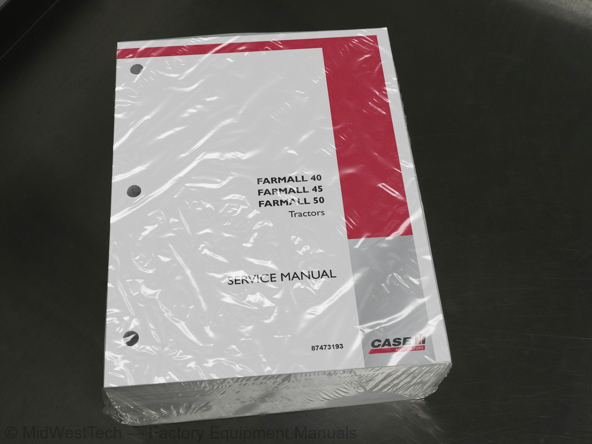
Case Farmall 40, 45, 50 Tractor Service Manual
1,415 pages · Publication 87473193
Added to your cart. View cart
- Models
- Farmall 40, 45, 50
- Manual type
- Service Manual
- Pages
- 1,415
- Publication
- 87473193
- Condition
- Brand new
What's inside
From the manual's own table of contents: 110 sections, 659 entries. See sample pages (PDF, 495 KB)
Hardware6 topics
- General
- Plating
- Nut Tightening
- Locknuts
- Jam Nuts
- Thread Lubrication
Safety7 topics
- The Tractor
- Servicing the Tractor
- Operating the Tractor
- Driving the Tractor
- Operating the PTO
- Diesel Fuel
- Safety Frame (ROPS)
Decals -- Farmall 40, 45, 50 with 12x12 Transmission2 topics
- Safety Decals
- Instruction Decals -- Farmall 40, 45, 50 with 12x12 Transmission
Decals -- Farmall 40, 45 with HST1 topic
- Instruction Decals -- Farmall 40, 45 with HST Transmission
Show all 110 sections
Special Tools1 topic
- Recommended Lubricants
Metric Bolt Torque Specifications1 topic
- Compression Test and Tools
Troubleshooting6 topics
- Cylinder Head and Valve Train Components
- Separating the Tractor at the Clutch Housing/Engine -- 12x12 Transmission
- Removal
- Separating the Tractor at the Engine/Frame
- Installation
- Attaching the 12x12 Transmission to the Engine
Overhaul75 topics
- Engine
- Fuel Injector and Glow Plug
- Oil Pressure Switch
- Temperature Sending Switch and Alternator
- Fan, Water Pump, and External Oil Tube
- Air Inlet Manifold
- Rocker Arm Shaft and Support Bracket
- Cylinder Head
- Valve Tappet
- Fuel Shutoff Solenoid
- Engine Timing Gear Cover, Timing Gears, and Cam Shaft
- Timing Gear Cover Removal
- Timing Gears and Camshaft
- Oil Sump
- Oil Suction Pipe and Strainer
- Balancer Assembly
- Connecting Rods, Bearings, and Pistons, Rings
- Flywheel
- Backplate and Oil Seal
- Crankshaft and Main Bearings
- Disassembly
- Inspection and Repair
- Valve Seats
- Valves
- Valve Guides
- Valve Springs
- Rocker Arms
- Push Rods
- Assembly
- Cylinder Block
- Pistons
- Disassembly and Inspection
- Piston Rings
- Connecting Rods
- Pin to Bushing Clearance
- Connecting Rod Bearing
- Clearance Check
- Pistons, Rings, and Connecting Rod
- Crankshaft -- Main Bearing and Thrust Washer
- Removal and Inspection
- Crankshaft
- Bearing (Bushing)
- Replacement
- Main Bearing
- Port Block
- Timing Gear
- Camshaft
- Inspection
- Timing Gear Housing
- Front Oil Seal and Steering Pump Seal
- Crankshaft and Bearing Holder
- Rear Oil Seal and Backplate
- Pistons and Connecting Rods
- Balancer Assembly (N844 and N844L Engines)
- Balancer Shims
- Oil Suction Pipe and Suction Strainer
- Camshaft and Camshaft Gear
- Idler Gear, Oil Pump, and Injection Timing
- Timing Gear Cover
- Crankshaft Pulley
- Fuel Injection Pump
- Hydraulic Oil Pump
- Power Steering Pump
- Head Gasket Selection
- Selection Chart
- Valve Clearance
- Adjustment
- Valve Cover
- Water Pump and Cooling Fan
- External Oil Tube
- Glow Plug and Connector
- Fuel Injector
- Fuel Piping
- Alternator and Temperature Sender Switch
- Exhaust Manifold
Description of Operation -- Engine Lubrication System8 topics
- Oil Filter
- Construction and Function
- Maintenance
- Oil Pump
- Installation and Adjustment
- Engine Oil Pressure
- Oil Pressure Relief Valve
- Oil Consumption
Description of Operation -- Cooling System5 topics
- Coolant
- Radiator Cap
- Thermostat
- Water Pump
- Cooling Fan
Overhaul -- Cooling System3 topics
- Radiator
- Cab Heater
- Standards for Adjusting the Injection Pump
Torque Specifications9 topics
- Injection Pump
- Fuel Injectors
- Governor
- Fuel Variation Mechanism
- Delivery Valve Assembly
- CTD (Compact Timing Device) Mechanism
- Pumping Elements
- Delivery Valves
- Repair
Calibration/Adjustments4 topics
- Fuel Pump
- Installation (New Pump or Drive Component)
- Spill-timing Procedure
- Fuel Screw/High Idle
Fuel Flow Chart8 topics
- Auto Bleed
- Fuel Lift Pump
- Specifications
- Troubleshooting
- Adjustments
- Injectors
- Assembly/Adjustment
- Engine Breather Valve
Bolt Torques2 topics
- Separating the Tractor at the Clutch Housing/Engine
- Clutch
Clutch Related Components4 topics
- Pilot Bearing
- Damper Disc
- Flywheel Dimensions
- Clutch Release Bearing
Clutch Linkage Components30 topics
- Cross Shaft Bushings
- Pedal Bushings
- Pedal
- Maximum Travel Adjustment
- Cross Section -- 12 x 12 Transmission
- Powerflow
- Clutch Housing
- Main Transmission
- Retainer Cover
- Main Shift Rails and Shift Forks
- Main Shaft
- Range Shift Rail and Shift Fork
- Range Gear Countershaft
- Input Shaft
- Reverse Idler Shaft
- Shuttle Shift Rail and Fork
- Main Countershaft
- Synchronizers
- Main Transmission Components
- Main Countershaft End Float
- Assembly -- Bearing (no preload)
- Range Shift Rail and Fork
- Main Shaft End Float
- Main Shift Rails and Forks
- Attaching the 12 x 12 Transmission to the Engine
- Transmission Shift Levers
- Main Shift Control Lever
- Main Shift Lever
- Shuttle Shift Control Lever
- Front to Rear Axle Ratio
Description of Operation -- FWD Front Axle1 topic
- FWD Front Axle
Lubrication1 topic
- Lubricate Every 50 Hours -- Standard FWD
Overhaul -- Standard FWD Axle31 topics
- Standard FWD Axle
- Gear Reduction Drop Box
- Front Axle and Differential
- Drive Pinion
- Front Axle
- Differential
- Gear Reduction—Drop Box
- Differential Gear
- Axle and Differential
- Differential Case Bearing Preload
- Check and Adjustment
- Gear Reduction Box
- Bevel Gear-to-Pinion Backlash
- Check
- Differential Lock
- Rear Axle
- Final Pinion
- Power Flow
- High Range
- Low Range
- Oil Flow
- Neutral Position
- Forward Position
- Reverse Position
- Variable Displacement Pump
- Two Position Displacement Motor
- Hi/Lo Speed Control/Control Pod
- Hi/Lo Speed Control
- Foot Control Pedals
- Charge Pump Relief Valve
- Test
Pressure Testing and Adjustments2 topics
- High Pressure Relief Valve
- Hi/Low Pressure Test
Separating the Tractor20 topics
- Farmall 40 and Farmall 45 w/HST Transmission
- Separating at the HST Housing/Engine
- Separating the HST Housing at the Gearbox
- Attaching the HST Housing to the Gearbox
- Attaching the HST to the Engine
- Hydrostatic Transmission
- Charge Pump
- Cylinder Block Assembly
- Motor Swash Plate
- Input and Output Shaft
- Pump Swash Plate
- Piston
- Swash Plate
- Pump Shaft (Input Shaft)
- Cylinder Block Assembly for Pump
- Assembly for Pump
- Motor Shaft
- Cylinder Block Assembly for Motor
- Assembly for Motor
- Check Valve
Description and Operation -- Gearbox2 topics
- Gearbox
- Gearbox Identification
Overhaul -- Gearbox19 topics
- Hi/Lo Solenoid Valve
- Testing
- Adapter Block
- Cruise Control
- Electromagnet Air Gap Adjustment
- HST Pedals
- Stop Adjustment
- HST Cruise Control Magnet
- HST Foot Control Pedals
- Neutral Adjustment
- HST Pedals Return Spring
- PTO Hydraulic System
- PTO Clutch
- Rear PTO
- Power Flow Diagram for the 12x12 Synchronized Shuttle Shift Transmission
- Power Flow Diagram for the Hydrostatic Transmission (HST)
- Power Flow Diagram for Tractors Equipped with a Mid PTO Kit
- Hydraulic Fluid Flow
- PTO Clutch Assembly
Pressure Testing29 topics
- Test Procedure
- PTO System Diverter Valve Assembly
- PTO Clutch Control Valve
- Power Take Off System for 12x12 Synchronized Shuttle Shift Transmission
- PTO Input Shaft
- PTO Countershaft and Rear PTO Shaft
- Power Take Off System for Hydrostatic Transmission (HST)
- Mid PTO Countershaft and Drop Box
- Brakes
- Park Brake
- Removal and Disassembly
- Assembly and Installation
- Flow Priority
- Hydraulic System
- Hydraulic Fluid Filter
- Combination System Relief -- Diverter Valve Manifold Assembly
- Control Valve Assembly (HPL)
- Fluid Flow
- Raising Position
- Lowering Position
- Bypass Spool -- Fluid Flow
- Flow Control Valve
- Single Lever -- Position Control
- Neutral Position to Raise
- Raise Position to Neutral Position
- Neutral Position to Lowering Position
- Main System Relief Valve
- Inlet Restriction
- Pump Efficiency
Overhaul -- Hydraulic System5 topics
- Lift Cylinder
- Hydraulic Control Valve
- Combination System Relief Valve and Diverter Valve Assembly
- HPL Linkage
- Adjustment Procedure
Description of Operation -- Hydraulic Pump and Filter4 topics
- Hydraulic Pump and Filter
- Hydraulic Pump
- Oil Pump Trial Running
- Sump Tube and Screen Filter
Description of Operation -- Remote Valves6 topics
- Remote Valves
- Rear (Single-Spool) Remote Valve
- Front (Double-Spool) Remote Valve
- Rear (Single-spool) Remote System -- Fluid Flow
- Remote Cylinder Extending
- Remote Cylinder Retracting
Front Remote (Two Spool) Loader Control Valve Fluid Flow Diagrams26 topics
- Bucket Control
- Neutral/Lift Control-Neutral
- Dumping/Lift Control-Neutral
- Dumping REGEN/Lift Control-Neutral
- Roll Back/Lift Control-Neutral
- Neutral/Lift Control-Raising
- Neutral/Lift Control-Lowering
- Neutral/Lift Control-Float
- Front (Double Spool) Remote Valve
- Power Steering System
- Steering Cylinder -- FWD
- Power Steering Operation -- FWD
- Fluid Flow -- Neutral Position
- Fluid Flow -- Left Turn
- Fluid Flow -- Right Turn
- Manual Operation -- FWD
- Pump, Steering Motor, and Relief Valve
- Steering Cylinder
- Steering Control Motor
- Pump
- Break--in Procedure
- Compressor
- Refrigerant
- Refrigerant Oil
- Low Pressure Switch
- High Pressure Switch
Description and Operation12 topics
- Condenser
- Evaporator
- Expansion Valve
- Receiver/Drier
- Heater
- Heater System
- HVAC Control Panel
- Cab Air Filter
- Cleaning Cab Air Filter
- Compressor Protection Switches
- High-Pressure Cutout Switch
- Low-Pressure Cutout Switch
Component Location23 topics
- Cab and Engine Bay
- Cab Roof
- Expansion Valve -- Testing
- Temperature/Pressure Chart
- Service Precautionary Statements
- Leak Testing
- Refilling
- Contaminants
- Preventing Mixing of Service Equipment
- Refrigerant Extraction and Recycling Equipment
- Using Extraction Equipment
- Using Recycling Equipment
- Recycling vs. Reclaiming
- Containment of Air Conditioning Refrigerants
- Recovery
- Flushing
- Recharging/Refilling
- Using a Manifold Gauge Set
- Checking Refrigerant for Excess Air
- Containers for Storing Recycled Refrigerant
- Disposal of Empty or Near-empty Disposable Containers
- Applicable SAE Standards
- Related SAE Standards
Manifold Gauges and Interpretations1 topic
- Performance Test Examples
Charging8 topics
- Belt Replacement
- Specification
- HVAC Controls
- Heater Valve
- Evaporator/Heater Core Replacement
- Temperature Sensor
- Blower Motor/Blower Motor Resistor
- A/C Compressor
Compressor Assembly Torques109 topics
- Compressor Breakdown
- Clutch Breakdown
- Compressor Repaired Internally and Reinstalled in the System
- of the Same Type
- Clutch Head Repair
- Keyed Shaft Armature Removal
- Rotor Assembly Removal
- Field Coil Assembly Removal
- Field Coil Assembly Installation
- Rotor Assembly Installation
- Armature Assembly Installation
- Replacement of Shaft Seal
- Cylinder Head Removal
- Valve Plate Removal
- Valve Plate and Cylinder Head Installation
- Component Location and Function
- Wiring Harnesses
- Grounds
- Electrical System Components
- Battery
- Checking the Electrolyte Level
- Main Fuse
- Fuse Block
- Gear Model Tractors
- HST Model Tractors
- Key Switch
- Terminal Identification
- Stop Position (Not Shown)
- Heat/ Accessory/ Run Position
- Start Position
- Light Switch (Road Lights)
- Light Switch Testing
- Off” Position
- Taillight/Instrument Panel” Position (Middle Position)
- Headlight Position” (Forward Position)
- Light Switch Installation
- Headlight
- Taillight
- Hazard Light Switch
- On” Position
- Transmission Range Safety Switch (HST and Gear)
- Extended Position
- Retracted Position (Not Shown)
- Rear (Main) PTO Safety Switch
- Retracted Position
- Mid PTO Safety Switch (Optional for HST Models Only)
- Seat Safety Switch
- Description
- Park Brake Safety Switch
- Extended Position (Not Shown)
- Relays
- HSFarmall Series Relay Panel Identification
- Gear Series Relay Panel Identification
- Testing-Micro Relays
- PTO Safety Relays
- Headlight, Neutral Start and Starter Relays
- Glow Plug Power Relay
- Diodes
- Module Testing
- Diode Testing
- Operator Safety Module
- Glow Plug Timer
- Engine Glow Plugs
- Hazard Flasher/Turn Signal Control Module
- Fuel Level Sending Unit
- Engine Oil Pressure Switch
- Engine Coolant Temperature Sending Unit
- Hi/Low Transmission Range Switch (HST)
- Optional Testing
- Hi/Low Transmission Range Solenoid (HST)
- Electric Cruise Control Switch (HST)
- Cruise Control Magnet (HST)
- Cruise Control Brake Release Switch (HST)
- Electrical Schematic Diagram
- Safety Start Circuit (Operator Present) (Gear Model)
- Safety Start Circuit (Operator Present) (HST Model)
- Safety Start Circuit (Operator Not Present) (Gear Model)
- Safety Start Circuit (Operator Not Present) (HST Model)
- Safe Operation Circuit (Operator Present) (Gear & HST Models)
- Safe Operation Circuit (Operator Not Present) (Gear Model)
- Safe Operation Circuit (Operator Not Present) (HST Model)
- Glow Plug Circuit (Gear Model)
- Glow Plug Circuit (HST Model)
- Main Headlight Circuit (Gear Model)
- Main Headlight Circuit (HST Model)
- Hazard Flasher Circuit (Gear Model)
- Hazard Flasher Circuit (HST Model)
- Right Turn Signal Circuit (Gear Model)
- Right Turn Signal Circuit (HST Model)
- Left Turn Signal Circuit (Gear Model)
- Left Turn Signal Circuit (HST Model)
- PTO Indicator Light Circuit (Gear Model)
- PTO Indicator Light Circuit (HST Model)
- Engine Coolant Temperature Circuit (Gear Model)
- Engine Coolant Temperature Circuit (HST Model)
- Engine Low Oil Pressure Indicator Light Circuit (Gear Model)
- Engine Low Oil Pressure Indicator Light Circuit (HST Model)
- Fuel Level Circuit (Gear Model)
- Fuel Level Circuit (HST Model)
- Park Brake Indicator Light Circuit (Gear Model)
- Park Brake Indicator Light Circuit (HST Model)
- Tachometer Circuit (Gear Model)
- Tachometer Circuit (HST Model)
- Auxiliary Power Socket Circuit (HST Model)
- Cruise Control Circuit (HST Transmission)
- HST Range “Low” Shift Circuit
- HST Range “High” Shift Circuit
- Charging Circuit (Gear Model)
- Charging Circuit (HST Model)
Component Operation and Servicing (Gear Transmission)1 topic
- Instrument Panel (Gear Transmission)
Component Testing4 topics
- Fuel Gauge
- Temperature Gauge
- Tachometer
- As Viewed from the Rear of the Instrument Panel
Component Operation and Servicing (HST Transmission)2 topics
- Instrument Panel (HST Transmission)
- Instrument Panel
Component Testing and Replacement4 topics
- Proof Meter (hour meter)
- Instrument Panel Indicator and Illumination Lights
- Bulb Identification Chart
- Bulb Replacement
Charging System17 topics
- Alternator
- Charging Circuit
- Principle of IC Regulator
- Preliminary Alternator Tests
- Alternator Drive Belt
- Alternator Output
- Alternator Removal
- Alternator Disassembly
- Alternator Component Testing and Inspection
- Stator
- Rotor
- Rectifier Assembly
- Alternator Brushes
- Alternator Bearings
- Drive Pulley
- Alternator Frames
- Alternator Bench Check
Starting System28 topics
- Starter Components
- Starter Motor Assembly
- Starter Solenoid
- Pinion Clutch
- Electrical Testing
- Armature
- Brush Holder
- Field Coil
- No Load Test
- Fuse Blocks
- Multi Function Stalk Switch (Lights, Turn Signals, Horn)
- Switch Testing
- Headlights
- Taillight/Rear Flasher light
- Front Flasher Warning Light/Turn Signals
- Cab Work Lights
- Transmission Range Safety Switch
- Extended Position (PTO “ON”)
- Retracted Position (PTO “OFF”)
- Mid PTO Safety Switch (Optional)
- Farmall Series Relay Panel Identification
- Relay Identification
- Head Lights, and HVAC Relays
- Headlight, Neutral Start, and Cab Power Relays
- Installation (All Relays)
- Park Brake Safety Alarm (Buzzer)
- Optional Joystick Switch Testing
- Cab to Tractor Harness Main Connectors
Component Operation and Servicing22 topics
- Hood
- Rear Hood Side Panels
- Dash Console
- Seat -- Gear Models
- Seat -- HST Models
- ROPS
- Fuel Tank
- Fenders -- Gear Models
- Fenders -- HST Models
- Deck -- Gear Models
- Deck -- HST Models
- Rear Hood Panels
- Operator’s Seat
- Front Wiper Motor
- Washer Tank
- Rear Wiper Motor
- Door Handle and Latch
- Door Striker
- Cab Door
- Cab Rear Window
- Fenders
- Cab Lifting Fixture
Inside this manual
Real pages from this service manual (1,415 pages). Open the sample pages (PDF, 494 KB)
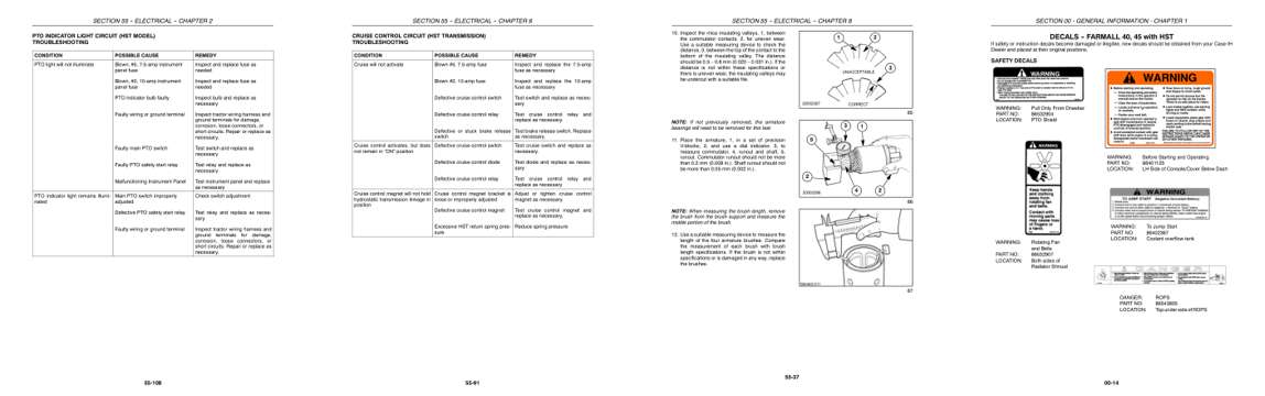
- Diagram, page 941: SECTION 55 -- ELECTRICAL -- CHAPTER 2
- Troubleshooting, page 1,214: SECTION 55 -- ELECTRICAL -- CHAPTER 6
- Specifications, page 1,298: SECTION 55 -- ELECTRICAL -- CHAPTER 8
- Color page, page 67: SECTION 00 - GENERAL INFORMATION - CHAPTER 1
Other manuals for this machine
Save 10% on 2 manuals, 15% on 3 or more. Other manuals for the 50 are listed below. Editions cover different serial number ranges: check the serial coverage and tick only the ones that match your machine.
Added to your cart. View cart
This is a service manual
Here's how it compares to the other manual types.
Service manual
Factory repair procedures and technical information such as specifications, troubleshooting, and wiring and hydraulic diagrams, for the models and systems the manual covers. See What's inside for its topics.
Operator's manual
Safe operation, controls, maintenance schedules, lubrication points, inspections, and basic checks. Repair procedures are in the service manual.
Parts manual
Illustrated diagrams with factory part numbers for identifying components and ordering parts. Repair procedures are in the service manual.
Engine service manuals are sometimes sold separately, since certain machine models were offered with more than one engine option.
What it's used for
Factory manual for in-house farm and construction shop use. Straightforward, complete, and easy to follow. It contains the OEM information dealership service departments and parts counters use to diagnose problems, identify components, and perform maintenance or repairs correctly.
Service shops and owner/operators who repair their own equipment
Identifying correct parts and seeing how assemblies come apart and go back together
Keeping equipment running with less downtime
Factory manual, 1,415 pages
Quantity one is the manual described above.
Fast free USA shipping
Ships in 1 business day.
60-day returns
Free if the mistake is ours. A manual ordered in error must come back unopened in its shrink-wrap; you pay return shipping and a 20% restocking fee applies. Return policy
Binder not included
Manuals over about 300 pages may need a standard 3-ring binder, which you can buy locally to keep the pages organized for shop use.
Questions about model, serial number, engine coverage or contents? Contact us before purchasing and we'll help confirm it's the right manual. Please verify the manual type, machine model, serial number range and engine coverage before purchasing: manuals ordered in error carry a 20% restocking fee (return policy).