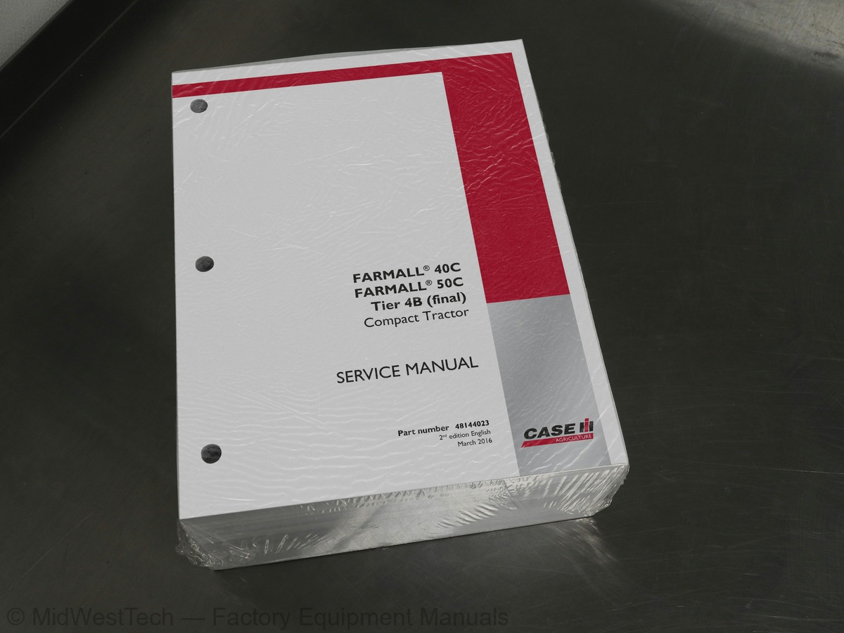
Case Farmall 40C, 50C Tier 4B Compact Tractor Service Manual
1,811 pages · Publication 48144023B
Added to your cart. View cart
- Models
- Farmall 40C, 50C Tier 4B
- Manual type
- Service Manual
- Pages
- 1,811
- Publication
- 48144023B
- Condition
- Brand new
What's inside
From the manual's own table of contents: 433 topics. See sample pages (PDF, 583 KB)
- Foreword (*)
- Safety rules (*)
- Safety rules Service precautionary statements climate control
- Safety rules – Personal safety (*)
- Safety rules - Ecology and the environment (*)
- Basic instructions - Important notice regarding equipment servicing (*)
- Basic instructions Important “Notice” regarding equipment servicing (*)
- Basic instructions - Shop and assembly (*)
- Torque - Minimum tightening torques for normal assembly (*)
- Torque Standard torque data for hydraulics (*)
- General specification (*)
- General specification – Biodiesel usage (*)
- Consumables (*)
- Dimension (*)
- Product identification (*)
- Product identification Machine orientation (*)
- Engine and crankcase
- Air cleaners and lines
- Fuel filters
- Engine lubrication system
- Engine cooling system
- Exhaust Gas Recirculation (EGR) exhaust treatment
- Remove (*)
- Install (*)
Show all 433 topics
- Engine - Exploded view air cleaner (*)
- Engine - Cleaning - Primary element (*)
- Engine - Replace - Air cleaner inner safety element (*)
- Engine - Remove air cleaner housing (*)
- Engine - Install air cleaner housing (*)
- Dynamic description – Sensor (*)
- Replace fuel filter (*)
- Replace pre fuel filter (*)
- Engine - Remove – Sensor (*)
- Test – Sensor (*)
- Install – Sensor (*)
- Exploded view (*)
- Drain fluid (*)
- Dynamic description
- Static description
- Component localization of emission component locations
- Dynamic description of the glow plug
- Dynamic description - Reed valve
- Remove
- Inspect
- Install
- Inspect – Differential pressure sensor
- Clutch hydraulic release control - Exploded view - Clutch linkage, Gear Transmission (*)
- Dynamic description (*)
- Clutch hydraulic release control - Dynamic description - Clutch pedal safety switch (*)
- Remove - Clutch pedal safety switch (*)
- Test - Clutch pedal safety switch (*)
- Install - Clutch pedal switch (*)
- Clutch hydraulic release control - Remove - Release bearing (*)
- Clutch hydraulic release control - Install - Release bearing (*)
- Clutch hydraulic release control - Adjust (*)
- Clutch hydraulic release control - Check - Engagement and slippage (*)
- Housing - Sectional view - Gear transmission (*)
- Exploded view damper (*)
- Disassemble (*)
- Assemble (*)
- Dynamic description 16 x 16 gear transmission (*)
- Exploded view main shaft (*)
- Exploded view Tractors with mechanical (Gear) transmissions (*)
- Exploded view main gear shaft HST transmission (*)
- Exploded view PTO shaft mechanical transmission (*)
- Exploded view PTO shaft HST transmission (*)
- Exploded view range gear shaft mechanical transmission (*)
- Exploded view range gear shaft HST transmission (*)
- Exploded view mid PTO drive shaft (*)
- Exploded view 4WD shaft (*)
- Exploded view 4WD shift lever and fork 4WD (*)
- Exploded view shift lever and fork mechanical transmission (*)
- Exploded view shift lever and fork (range gear) (*)
- Exploded view shift lever and fork (main gear) (*)
- Exploded view shift lever and fork (range gear) HST transmission (*)
- Exploded view forward and reverse rail and fork assembly (*)
- Exploded view transmission center casing front section (*)
- Exploded view center casing - rear section (*)
- Exploded view center casing cover (*)
- Disconnect the tractor at the clutch housing (*)
- Connect the clutch housing to the engine block (*)
- Install clutch housing (*)
- Disassemble shift lever (*)
- Assemble shift lever (*)
- Change fluid (*)
- Overview - Forward and reverse shuttle lever (Mechanical) (*)
- Exploded view synchronizer assembly (*)
- Remove - Four wheel drive shaft (*)
- Install - Four wheel drive shaft (*)
- Remove - Power Take-Off (PTO) shaft (*)
- Install - PTO shaft (*)
- Disassemble - Forward/reverse shift rail disassemble (*)
- Disassemble - Transmission disassemble (*)
- Assemble - Transmission assemble (*)
- Check gap at synchronizer (*)
- Disassemble Synchronizer disassemble (*)
- Assemble - Synchronizer assemble (*)
- Powered front axle
- Front bevel gear set and differential
- Final drive hub, steering knuckles, and shafts
- Final drives
- Torque Newton metres / Lb. ft. (*)
- General specification - Steering axle adjustments (*)
- Tire ratios (*)
- Exploded view case components (*)
- Exploded view front drive shaft seal (*)
- Exploded view tie rods (*)
- Overview Front-Wheel Drive(FWD) lever (*)
- Detailed view (*)
- Exploded view – Automatic vent (*)
- Filling (*)
- Exploded view – Pinion gear and shaft (*)
- Exploded view gear assembly (*)
- Backlash (*)
- Install - King pin housing seal installation (*)
- Install - Steering arm installation (*)
- Bevel gear set and differential carrier - Remove (*)
- Bevel gear set and differential carrier - Install (*)
- Remove cover, bearings, shims, and seals (*)
- Install cover, bearings, shims, and seals (*)
- Backlash check (*)
- Adjust backlash (*)
- Exploded view rear differential (*)
- Overview (*)
- Exploded view differential lock components HST transmission (*)
- Exploded view differential lock components 16 x 16 mechanical transmission (*)
- Exploded view rear axle and final drive housing (*)
- Remove – Bearings and seal (*)
- Driving wheel shaft - Install Rear axle seal (*)
- Install – Bearings and seal (*)
- Install housing to axle casing (*)
- Dynamic description – Hydrostatic Transmission (HST) neutral switch (*)
- Sectional view HST housing (*)
- External view HST pump and motor housing (*)
- Transmission command - Remove - Hydrostatic Transmission (HST) neutral switch (*)
- Transmission command - Test – Hydrostatic Transmission (HST) neutral switch (*)
- Transmission command - Install – Hydrostatic Transmission (HST) neutral switch (*)
- Hydraulic schema Oil flow HST system (*)
- Dynamic description - HST filter base (*)
- Dynamic description – Speed ranges (*)
- Exploded view – Range gears (*)
- Exploded view pump and motor cylinder block assembly (*)
- Exploded view high pressure relief valve (*)
- Dynamic description Hydrostatic drive - Hydrostatic transmission (*)
- Exploded view port block (*)
- Exploded view HST linkage (*)
- Remove HST unit (*)
- Disassemble HST unit (*)
- Assemble HST unit (*)
- Install - HST unit (*)
- Pressure test HST charge pressure (*)
- Pressure test HST relief valve (*)
- Check - neutral adjustment (*)
- Adjust HST pedal return spring (*)
- Check pedal linkage (*)
- Change fluid change fluid (*)
- Replace - Filter (*)
- Rear mechanical control
- Rear electro-hydraulic control
- One-speed rear Power Take-Off (PTO)
- Central Power Take-Off (PTO)
- Remove HST and gear tractors (*)
- Install HST and gear tractors (*)
- Power Take-Off (PTO) clutch - Hydraulic schema (*)
- Power Take-Off (PTO) clutch - Electrical schema (*)
- Front drive shaft - Remove – Rear Power Take-Off (PTO) shaft (*)
- Front drive shaft - Install - Rear Power Take-Off (PTO) shaft (*)
- Pressure test (*)
- Power Take-Off (PTO) clutch - Troubleshooting - Rear PTO and Mid PTO do not operate (*)
- Dynamic description – Switch (*)
- Remove - Switch (*)
- Test - Switch (*)
- Install - Switch (*)
- Static description (*)
- Remove the parking brake micro switch, lever and cable (*)
- Adjust (*)
- Troubleshooting (*)
- Exploded view brake linkage 16 x 16 mechanical transmission (front) and (rear) (*)
- Exploded view brake linkage HST transmission (front) and (rear) (*)
- Exploded view Brake components (*)
- Adjust brake pedal free-travel (*)
- Hydraulic systems
- Fixed displacement pump
- Three-point hitch control valve
- Three-point hitch cylinder
- Remote control valves
- Reservoir, cooler, and filters
- Safety and main relief valves
- Hydraulic hand control
- Static description - mechanical transmission
- Static description - hydrostatic transmission
- Hydraulic schematic frame 01 – Gear transmission
- Hydraulic schematic frame 02 - Hydrostatic transmission
- Flow test (*)
- Functional diagram - (*)
- Static description – Hydraulic Power Lift (HPL) drop rate valve (*)
- Functional diagram – Hydraulic Power Lift (HPL) drop rate valve (*)
- Adjust – Internal linkage (*)
- Disassemble - Hydraulic Power Lift (HPL) drop rate (*)
- Assemble - Hydraulic Power Lift (HPL) drop rate (*)
- Static description - Hydraulic Power Lift (HPL) lift cylinder (*)
- Dynamic description - Front two spool valve (*)
- Open center mechanical remote valve - Static description - Front two spool (*)
- Detailed view – Front two spool (*)
- Open center mechanical remote valve - Static description – Rear (*)
- Detailed view – Rear (*)
- Disassemble - Front spools and joystick (*)
- Assemble - Front spools and joystick (*)
- Overview - oil cooler bypass valve mechanical transmission
- Overview - oil cooler and HST filter bypass valves HST transmission
- Remove oil cooler HST transmission (*)
- Install cooler HST transmission (*)
- Remove oil cooler mechanical transmission (*)
- Install oil cooler mechanical transmission (*)
- Replace - Hydraulic system (*)
- Remove – Joystick (*)
- Install – Joystick (*)
- Dynamic description – Mechanical draft control (*)
- Dynamic description - Hydraulic Power Lift (HPL) system (*)
- Static description – Hydraulic Power Lift (HPL) (*)
- Remove - Hydraulic Power Lift (HPL) housing (*)
- Install – Hydraulic Power Lift (HPL) housing (*)
- Adjust – Mechanical draft control (*)
- Steering control
- Tie rods
- Hydraulic control components
- Cylinders
- Exploded view – Steering wheel (*)
- Powered front axle - Exploded view tie rods (*)
- General specification – Pump (*)
- Remove – steering valve (*)
- Remove - Steering valve (*)
- Disassemble – Steering valve (*)
- Assemble – Steering valve (*)
- Install – Steering valve (*)
- Troubleshooting - For the steering control unit (*)
- Exploded view steering cylinder and lines, mechanical transmission (*)
- Exploded view HST transmission (*)
- Disconnect (*)
- Inspect (*)
- Overhaul assembly (*)
- Connect (*)
- Dynamic description of the heating system (*)
- Service instruction
- Remove HVAC controls (*)
- Install HVAC controls (*)
- Disassemble air conditioning and heater components (*)
- Assemble air conditioning and heater components (*)
- Dynamic description of the fan and motor
- Dynamic description of the resistor (*)
- Wiring schema simplified (*)
- Dynamic description cab air filter (*)
- Ventilation - Dynamic description vents (*)
- Remove the resistor (*)
- Install the resistor (*)
- General specification - Ambient temperature versus manifold pressure gauge reading (*)
- General specification - Temperature/pressure Chart (*)
- Technical Data refrigerant (*)
- Special tools (*)
- General specification Air Conditioning (*)
- Component localization and heat components in cab (*)
- Dynamic description flushing A/C system (*)
- Air-conditioning compressor - Component localization in the engine compartment (*)
- Dynamic description refrigerant flow diagram (*)
- Dynamic description dual pressure switch (*)
- Exploded view dual pressure switch (*)
- Dynamic description clutch (*)
- Dynamic description internal structure and function (*)
- Dynamic description of the evaporator temperature sensor (*)
- Electrical system
- Fuel tank system
- Parking brake electrical system
- Rear Power Take-Off (PTO) control system
- Harnesses and connectors
- Engine starting system
- Cold start aid
- Battery
- External lighting
- External lighting switches and relays
- Warning indicators, alarms, and instruments
- Cab transmission controls
- Cab engine controls
- Ground speed control
- Electronic modules
- Exhaust Gas Recirculation (EGR) electrical system
- FAULT CODES
- Component identification (*)
- Electrical schematic sheet 01 - Complete tractor schematic front half - HST (*)
- Electrical schematic sheet 02 Complete tractor schematic rear half - HST (*)
- Electrical schematic sheet 03 Complete tractor schematic engine - HST (*)
- Electrical schematic sheet 04 Complete tractor schematic front half - Gear (*)
- Electrical schematic sheet 05 Complete tractor schematic rear half - Gear (*)
- Electrical schematic sheet 06 Complete tractor schematic engine - Gear (*)
- Overview Starting circuit (HST) transmission (*)
- Overview Starting circuit gear transmission (*)
- Overview Safe operation, operator present, HST transmission (*)
- Overview Safe operation, operator not present, HST transmission (*)
- Overview Safe operation, operator present, gear transmission (*)
- Overview Safe operation, operator not present, gear transmission (*)
- Overview Glow plugs (*)
- Overview Work lights (*)
- Overview Hazard lights (*)
- Overview Road lights (*)
- Overview Turn signals (*)
- Overview Park brake indicator light (*)
- Overview Brake lights (*)
- Overview HST cruise control (*)
- Overview PTO (*)
- Overview Horn (*)
- Overview Battery charge (*)
- Overview Diesel Particulate Filter (DPF) regeneration process (*)
- Remove – Switch (*)
- Test – Switch (*)
- Install – Switch (*)
- Dynamic description – PTO switch (*)
- Remove – PTO switch (*)
- Test – PTO switch (*)
- Install – PTO switch (*)
- Electrical schematic sheet 01 – Power distribution (mechanical transmission, ROPS models) (*)
- Electrical schematic sheet 02 – Power distribution (mechanical transmission, ROPS models) (*)
- Electrical schematic sheet 04 – Grounding (mechanical transmission, ROPS models) (*)
- Electrical schematic sheet 07 – Rear lighting (mechanical transmission, ROPS models) (*)
- Electrical schematic sheet 08 – Safety controller (mechanical transmission, ROPS models) (*)
- Electrical schematic sheet 09 – Instrument panel (mechanical transmission, ROPS models) (*)
- Electrical schematic sheet 10 – Instrument panel (mechanical transmission, ROPS models) (*)
- Electrical schematic sheet 11 – Trailer connector (mechanical transmission, ROPS models) (*)
- Electrical schematic sheet 12 – Throttle control (mechanical transmission, ROPS models) (*)
- Electrical schematic sheet 14 – Hood lighting (mechanical transmission, ROPS models) (*)
- Electrical schematic sheet 16 – Schematic legends (mechanical transmission, ROPS models) (*)
- Electrical schematic sheet 04 – Grounding (Hydrostatic Transmission (HST), ROPS models) (*)
- Electrical schematic sheet 07 – Rear lighting (Hydrostatic Transmission (HST), ROPS models) (*)
- Troubleshooting - HST transmission (*)
- Troubleshooting - Gear transmission (*)
- Dynamic description - Glow plugs (*)
- Dynamic description - Glow plug relay (*)
- Remove – Glow plugs relay (*)
- Test – Glow plugs relay (*)
- Install – Glow plugs relay (*)
- Remove - Glow plug (*)
- Test - Glow plug (*)
- Install - Glow plug (*)
- Electrical test using DATAR (*)
- Dynamic description - Brake lights relay (*)
- Replace - Bulb (*)
- Front - Troubleshooting (*)
- Dynamic description - Road lights relay (*)
- Dynamic description - Combination light switch (*)
- Remove Brake lights relay (*)
- Test - Brake lights relay (*)
- Install - Brake lights relay (*)
- Remove – Road lights relay (*)
- Test - Road lights relay (*)
- Install - Road lights relay (*)
- Remove - Combination light switch (*)
- Test - Combination light switch (*)
- Install - Combination light switch (*)
- Dynamic description - Safety controller (*)
- Dynamic description - Safety alarm (*)
- Dynamic description – Horn switch (*)
- Dynamic description – Horn (*)
- Remove - Safety alarm (*)
- Test - Safety alarm (*)
- Install - Safety alarm (*)
- Remove - Horn switch (*)
- Test - Horn switch (*)
- Install - Horn switch (*)
- Remove - Horn (*)
- Install - Horn (*)
- Seat switch - Remove (*)
- Seat switch - Test (*)
- Seat switch - Install (*)
- Analog instrument cluster - Remove - Safety controller (*)
- Analog instrument cluster - Test - Safety controller (*)
- Analog instrument cluster - Install - Safety controller (*)
- Analog instrument cluster - Remove (*)
- Install Clutch pedal safety switch (*)
- Dynamic description - Main relay (*)
- Dynamic description - Burner relay (*)
- Dynamic description – Cruise control switch (*)
- Dynamic description – Cruise control magnet (*)
- Remove - Main relay (*)
- Test - Main relay (*)
- Install - Main relay (*)
- Remove - Burner relay (*)
- Test - Burner relay (*)
- Install - Burner relay (*)
- Remove - Cruise control switch (*)
- Test – Cruise control switch (*)
- Install – Cruise control switch (*)
- Remove – Cruise control magnet (*)
- Test – Cruise control magnet (*)
- Install - Cruise control magnet (*)
- Dynamic description - Cruise control switch (*)
- Dynamic description - Forward/Reverse Shuttle Switch (*)
- Test - Cruise control switch (*)
- Install - Cruise control switch (*)
- Remove - Cruise control magnet (*)
- Test - Cruise control magnet (*)
- Remove – Forward/Reverse Shuttle Switch (*)
- Test – Forward/Reverse Shuttle Switch (*)
- Install – Forward/Reverse Shuttle Switch (*)
- Dynamic description – Fault codes (*)
- erational range [ECU] (*)
- 91-3-Accelerator pedal position #1: voltage above normal [ECU] (*)
- 91-4-Accelerator pedal position #1: voltage below normal [ECU] (*)
- 100-1-Engine oil pressure: low, most severe [ECU] (*)
- 102-3-Engine intake manifold #1 pressure: voltage above normal [ECU] (*)
- 102-4-Engine intake manifold #1 pressure: voltage below normal [ECU] (*)
- 108-3-Barometric pressure: voltage above normal [ECU] (*)
- 108-4-Barometric pressure: voltage below normal [ECU] (*)
- 110-3-Engine coolant temperature: voltage above normal [ECU] (*)
- 110-4-Engine coolant temperature: voltage above normal [ECU] (*)
- 110-15-Engine coolant temperature: high, least severe [ECU] (*)
- 168-0-Battery potential / power input 1: data valid but above normal operational range [ECU] (*)
- 168-3-Battery potential / power input 1: voltage above normal [ECU] (*)
- 168-4-Battery potential / power input 1: voltage below normal [ECU] (*)
- 172-3-Engine air inlet temperature: voltage above normal [ECU] (*)
- 172-4-Engine air inlet temperature: voltage below normal [ECU] (*)
- 190-0-Engine speed: Data valid but above normal operational range [ECU] (*)
- 190-8-Engine speed: abnormal frequency, pulse width, or period [ECU] (*)
- 558-3-Accelerator pedal #1 low idle switch: voltage above normal [ECU] (*)
- 558-4-Accelerator pedal #1 low idle switch: voltage below normal (*)
- 638-6-Engine fuel rack actuator (linear solenoid): current above normal or grounded circuit [ECU] (*)
- 723-3-Engine speed sensor #2(camshaft sensor): voltage above normal [ECU] (*)
- 723-4-Engine speed sensor #2 (camshaft sensor): voltage below normal [ECU] (*)
- Engine hood and panels
- Operator protections
- Fenders and guards
- Mechanically-adjusted operator seat
- Cab interior
- Cab doors and hatches
- Cab glazing
- Complete (*)
Inside this manual
Real pages from this service manual (1,811 pages). Open the sample pages (PDF, 582 KB)

- Specifications, page 971: Cab climate control - Air conditioning
- Diagram, page 1,279: Electrical systems - Harnesses and connectors
- Troubleshooting, page 1,699: Electrical systems - FAULT CODES
- Color page, page 1,050: FARMALL® 40C
- Color page, page 825: Steering - Hydraulic control components
- Foldout diagram (color), page 1,201: Electrical systems - Harnesses and connectors
Other manuals for this machine
Save 10% on 2 manuals, 15% on 3 or more. Other manuals for the Farmall 40C are listed below. Editions cover different serial number ranges: check the serial coverage and tick only the ones that match your machine.
Added to your cart. View cart
This is a service manual
Here's how it compares to the other manual types.
Service manual
Factory repair procedures and technical information such as specifications, troubleshooting, and wiring and hydraulic diagrams, for the models and systems the manual covers. See What's inside for its topics.
Operator's manual
Safe operation, controls, maintenance schedules, lubrication points, inspections, and basic checks. Repair procedures are in the service manual.
Parts manual
Illustrated diagrams with factory part numbers for identifying components and ordering parts. Repair procedures are in the service manual.
Engine service manuals are sometimes sold separately, since certain machine models were offered with more than one engine option.
What it's used for
Factory manual for in-house farm and construction shop use. Straightforward, complete, and easy to follow. It contains the OEM information dealership service departments and parts counters use to diagnose problems, identify components, and perform maintenance or repairs correctly.
Service shops and owner/operators who repair their own equipment
Identifying correct parts and seeing how assemblies come apart and go back together
Keeping equipment running with less downtime
Factory manual, 1,811 pages
Quantity one is the manual described above.
Fast free USA shipping
Ships in 1 business day.
60-day returns
Free if the mistake is ours. A manual ordered in error must come back unopened in its shrink-wrap; you pay return shipping and a 20% restocking fee applies. Return policy
Binder not included
Manuals over about 300 pages may need a standard 3-ring binder, which you can buy locally to keep the pages organized for shop use.
Other editions and similar models
Questions about model, serial number, engine coverage or contents? Contact us before purchasing and we'll help confirm it's the right manual. Please verify the manual type, machine model, serial number range and engine coverage before purchasing: manuals ordered in error carry a 20% restocking fee (return policy).