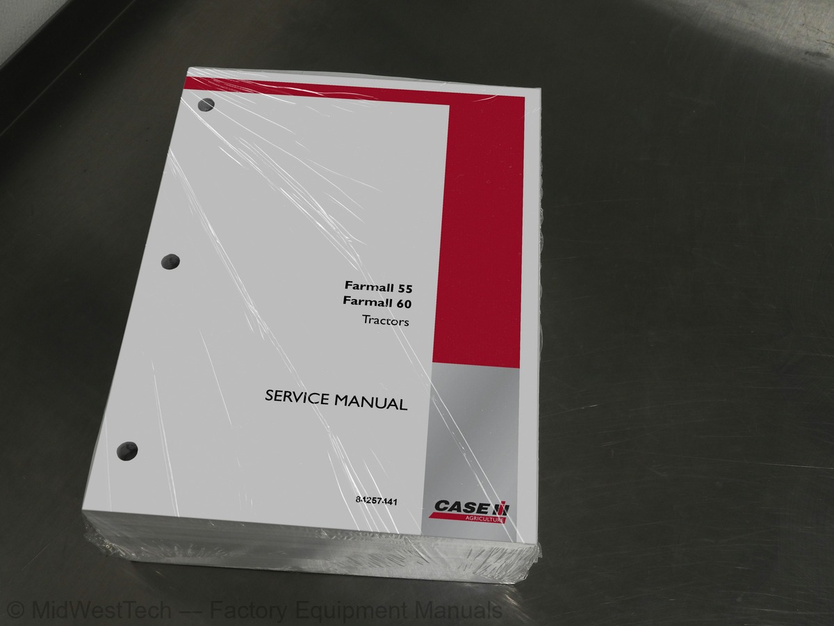
Case Farmall 55, 60 Tractor Service Manual
1,423 pages · Publication 84257441
Added to your cart. View cart
- Models
- Farmall 55, 60
- Manual type
- Service Manual
- Pages
- 1,423
- Publication
- 84257441
- Condition
- Brand new
What's inside
From the manual's own table of contents: 355 sections, 700 entries. See sample pages (PDF, 396 KB)
General Information2 topics
- Grease Fittings
- Chains 1
Diesel Fuel 2.0.001 topic
- Fuel Usage Safety 0.0.0
Wheel Tread Settings2 topics
- Front Axle (FWD) (Not Adjustable)
- Rear Axle (FWD)
Show all 355 sections
Engine 2.02 topics
- Removal
- Installation 0.0
Alternator and Temperature Sending Switch1 topic
- Removal
Glow Plug and Connector1 topic
- Removal
Fuel Injection Tubing1 topic
- Removal
Fuel Injector1 topic
- Removal
Cover/Intake Manifold/Exhaust Manifold1 topic
- Removal
External Oil Tube1 topic
- Removal
Rocker Assembly1 topic
- Removal
Fuel Stop Solenoid1 topic
- Removal
Timing Gears and Camshaft1 topic
- Removal
Front End Plate 2.0.0.01 topic
- Removal
Cylinder Head2 topics
- Disassembly
- Inspection and Repair
Rocker AMS1 topic
- Inspection 2.0
Cylinder BIOCK 2.0.03 topics
- Inspection and Repair
- Disassembly
- Inspection 2.0
Connecting Rods1 topic
- Inspection and Repair
Crankshaft Main Bearing and Thrust Washer3 topics
- Removal and Inspection
- Removal
- Installation
Oil Suction Tube and Suction Strainer 0.0.21 topic
- Installation
Front Oil Seal and Steering Pump Seal1 topic
- Replacement
Crankshaft Pulley1 topic
- Installation 0.0
Injection PUMP 12 topics
- Installation 00
- Head Gasket Selection Chart
External Oil Tube 1.01 topic
- Installation
Water Pump and Cooling Fan1 topic
- Installation
Alternator and Temperature Sender Switch1 topic
- Installation
Glow Plug and Connector1 topic
- Installation
Hydraulic Oil PUMP1 topic
- Installation
Power Steering PUMP1 topic
- Installation
Description of Operation - Engine Lubrication System4 topics
- Construction and Function
- Maintenance
- Removal
- Inspection
Maintenance1 topic
- Cooling System Capacity
Cooling Fan4 topics
- Removal
- Installation 0
- Removal
- Inspection and Repair
Thermostat 2.03 topics
- Removal
- Inspection and Repair
- Installation 0
Delivery Valves 1.0.02 topics
- Repair
- Installation 0.0
GOVEMNOF 24 topics
- Disassembly
- ASSEMDIY 0
- AdjustmentS
- Removal
Turbocharger9 topics
- Inspection Before Disassembly
- Turbine Shaft
- Bearings and Associated Parts
- Inserting the Shaft Into Bearing Casing
- Installing the Seal Plate
- Installing the Blower Wheel
- Installing the Turbine Casing
- Securing the Blower Casing to the Bearing Casing
- Installing the Waste Gate Controller Assembly
Separating the Tractor at Clutch Housing/Engine2 topics
- Removal
- Inspection
Clutch Release Bearing2 topics
- Inspection 2.6
- Installation
Oil Pump For EHSS and PTO Clutch6 topics
- Neutral Position . 0.0.0.0
- Forward Position
- Reverse Position
- Reverse Position - Inching Pedal Depressed
- Inching Pedal Depressed
- System Relief Valve Assembly
EHSS Control Valve Solenoid2 topics
- Flow Test
- Neutral and Forward
EHSS Transmission2 topics
- Removal - Separating the Tractor at Clutch Housing/Engine
- Installation - Attaching the Tractor at Clutch Housing/Engine
Main Transmission17 topics
- Disassembly - Separating the Transmission/Differential
- Shuttle Clutch Adapter/Input Shaft Retainer
- Input Shaft 2.0
- Reverse Idler Shaft and Gear
- Shift Rails
- Shuttle Clutch and Shaft
- PTO Shaft
- Countershaft
- Main Shaft
- ASSEMDbIY 2
- Shuttle Clutch 2.0
- Shift Rails
- Reverse Idler
- Input Shaft 20.0
- Shuttle Clutch Adapter/Input Shaft Retainer
- Attaching The Transmission/Differential
- Clutch HOUSING
Shuttle Clutch 2.03 topics
- Disassembly
- Inspection
- ASSOEMbIY 2
Synchronizers4 topics
- Disassembly
- Inspection
- Synchronizers 2.2
- ASSEMDIy 2
1st or 2nd Gear Engaged High and Forward Engaged2 topics
- Current FIOW
- Key Switch Placed in “RUN/ACC” Position
Potentiometer1 topic
- With the Inching Pedal (not depressed)
1st or 2nd Gear Engaged Low and Forward Engaged2 topics
- Current FIOW
- Key Switch Placed in “RUN/ACC” Position
Potentiometer 2.0.01 topic
- With the Inching Pedal (not depressed)
1st or 2nd Gear Engaged High and Reverse Engaged2 topics
- Current FIOW 0.0.6
- Key Switch Placed in “RUN/ACC” Position
Potentiometer 2.0.01 topic
- With the Inching Pedal (not depressed)
1st or 2nd Gear Engaged Low and Reverse Engaged2 topics
- Current FIOW
- Key Switch Placed in “RUN/ACC’ Position
Potentiometer1 topic
- With the Inching Pedal (not depressed)
3rd or 4th Gear Engaged High and Forward Engaged2 topics
- Current FIOW
- Key Switch Placed in “RUN/ACC” Position
Potentiometer1 topic
- With the Inching Pedal (not depressed)
8rd or 4th Gear Engaged Low and Forward Engaged2 topics
- Current FIOW
- Key Switch Placed in “RUN/ACC” Position
3rd or 4th Gear Engaged High and Reverse Engaged2 topics
- Current FIOW 0.0.6
- Key Switch Placed in “RUN/ACC” Position
Potentiometer 0.0.01 topic
- With the Inching Pedal (not depressed)
3rd or 4th Gear Engaged Low and Reverse Engaged2 topics
- Current FIOW
- Key Switch Placed in “RUN/ACC” Position
Potentiometer1 topic
- With the Inching Pedal (not depressed)
EHSS Controller Activation2 topics
- Current FIOW 0.0.6
- Key Switch Placed in “RUN/ACC” Position
Potentiometer1 topic
- With the Inching Pedal (free position)
EHSS Controller 2.0.0.01 topic
- Removal
EHSS Controller Testing8 topics
- 1st or 2nd Gear, High and Forward Circuit
- 1st or 2nd Gear, Low and Forward Circuit
- 1st or 2nd Gear, High and Reverse Circuit
- 1st or 2nd Gear, Low and Reverse Circuit
- 3rd or 4th Gear, High and Forward Circuit
- 3rd or 4th Gear, Low and Forward Circuit
- 3rd or 4th Gear, High and Reverse Circuit
- 3rd or 4th Gear, Low and Reverse Circuit
Activation Circuit1 topic
- Installation 0.0
Shuttle Switch (Forward/Reverse)2 topics
- Removal
- Installation
Transmission Modulation Switches4 topics
- Removal (ALL Switches)
- Main 1-2 Switch (ball located behind switch)
- HIGH” and “LOW” Range Switches
- Installation (ALL Switches)
Test Procedures - Switches8 topics
- High Range Switch
- Low Range Switch
- Neutral, 1st and 2nd Gear Switch
- Shuttle Switch (F-N-R)
- Neutral Test 2.0
- Forward Test
- Reverse Test 2.0
- Solenoid Test-EHSS Control Valve
Modulation Explanation2 topics
- Modulation Time Chart
- Modulation Time-Test Procedure
Overhaul 2.01 topic
- Disassembly
Main Transmission Input Shaft Retainer1 topic
- Disassembly
Shift Rails1 topic
- Disassembly
Countershaft1 topic
- Disassembly
Range Gear Shift Fork1 topic
- ASSOEMDbIY 2
Reverse Idler1 topic
- ASSOMDbIY 2
Synchronizers1 topic
- Inspection
Main Transmission Gears/Synchronizer1 topic
- ASSOMDbIY 2
Description of Operation - Front Wheel Drive Gearbox3 topics
- Counter Gear Removal
- Disassembly
- Inspection 20
Overhaul 0.61 topic
- Removal
Gear Reduction Drop Box2 topics
- Disassembly
- Inspection 2.0
Front Axle and Differential4 topics
- Disassembly
- Inspection 2.0
- Inspection
- ASSEMDbIY 0
Axle and Differential1 topic
- ASSEMbIY 1
Gear Reduction Box1 topic
- ASSOMDIY 2
Rear Axle 0.02 topics
- Assembly 1.0
- Installation 0
Drive Pinion4 topics
- Removal
- Disassembly
- Inspection
- ASSEMbly 2
Pressure Testing3 topics
- Test Procedure
- ROPS Models
- Adjustment 0.0.0
PTO Clutch Control Valve11 topics
- ROPS Models
- Cab Models
- Disassembly
- Inspection
- Installation 0.0
- ROPS Models
- Cab Models
- Disassembly
- Inspection
- ASSOMDIY 2
- Installation 0.0
Park Brake 23 topics
- Park Brake Return Spring
- Inspection . 6.0
- Assembly and Installation
Lift Cylinder 2.21 topic
- Removal
Drop Rate Control Valve5 topics
- Removal
- Disassembly
- Inspection 2.0
- ASSEMDly
- Inspection . 6.0
Combination System Relief Valve and Diverter Valve Assemblies4 topics
- Removal 0.0
- Disassembly
- Inspection
- Installation
AdjUStMentS 1.01 topic
- Adjustment Procedure
Hydraulic PUMP3 topics
- Removal
- ASSEMDbIY 2
- Break-in Procedure
Sump Tube and Strainer 6.0.01 topic
- Removal
(W/O Kick-out or Float) 2.0.01 topic
- LOWED
Bucket Control9 topics
- Neutral/Lift Control - Neutral
- Bucket Control - Dumping/Lift Control - Neutral
- Bucket Control - Dumping Regen/Lift Control - Neutral
- Bucket Control - Roll Back/Lift Control - Neutral
- Bucket Control - Neutral/Lift Control - Raising
- Bucket Control - Neutral/Lift Control - Lowering
- Bucket Control - Neutral/Lift Control - Float
- Disassembly
- Inspection
Rear Remote (Three Position, Single Spool) (Non-Detent)3 topics
- Removal
- Inspection 2.0
- Installation
Rear Remote (Four Position, Single Spool W/Detent Kick-out and Float)6 topics
- Removal
- Disassembly (Four Position Valve w/Detent and Float)
- Inspection
- ASSEMby 2
- Installation 0.0
- Detent Kick-out Adjustment
Power Steering Control Motor5 topics
- Spool and Sleeve
- Rotor and Fixed Ring
- Check ValVe 2.0
- Drive Shaft 2.0
- Pressure Relief Valve
Power Steering Cylinder1 topic
- Fluid Flow - Neutral Position
Pump, Steering Motor and Relief Valve2 topics
- Test ResultS 2.0
- Lubricate Every 50 Hours - FWD
Steering Control Motor3 topics
- Removal
- Disassembly
- Inspection
Steering Cylinder 2.04 topics
- Removal
- Disassembly
- Inspection and Repair
- Installation 0.0
Steering TUDES 201 topic
- Break-in Procedure
Wheel Tread Settings2 topics
- Front Axle: (FWD) (Not Adjustable)
- Rear Axle: (FWD) 2.0
Rear Wheel Weight Installation (Ag./Industrial Tires)2 topics
- Rear Wheel Weights #710470026
- Rear Counterweight Bracket (Optional) #718740016
Expansion Valve1 topic
- Cleaning Cab Air Filter 2.0
Compressor Protection Switches2 topics
- High-Pressure Cutout Switch
- Low-Pressure Cutout Switch
Service Precautionary Statements2 topics
- Leak Testing
- Refilling 2.0
Contaminants2 topics
- General
- Preventing Mixing of Service Equipment
Refrigerant Extraction and Recycling Equipment3 topics
- Using Extraction Equipment
- Using Recycling Equipment
- Recycling vs. Reclaiming
Containment of Air Conditioning Refrigerants6 topics
- RECOVETY 2
- Recharging/Refilling
- Using a Manifold Gauge Set
- Checking Refrigerant for Excess Air
- Containers for Storing Recycled Refrigerant
- Disposal of Empty or Near-empty Disposable Containers
Applicable SAE Standards1 topic
- Related SAE Standards
Belt Replacement1 topic
- Specification 2.0.0
HVAC Controls 1.21 topic
- Removal
Heater Valve 01 topic
- Installation 0
Condenser and Receiver/Dryer2 topics
- Removal
- Installation
Evaporator/Heater Core Replacement3 topics
- Removal
- Disassembly
- ASSEMDIy 12
Temperature Sensor1 topic
- Removal
Blower Motor/Blower Motor Resistor3 topics
- Disassembly
- ASSEMbIy 2
- Installation 6.0
Low Pressure Switch 1.0.0.01 topic
- Replacement
High Pressure Switch1 topic
- Replacement
A/C Compressor1 topic
- Removal
Clutch Breakdown2 topics
- Compressor Repaired Internally and Reinstalled in the System
- of the Same Type
Clutch Head Repair6 topics
- Keyed Shaft Armature Removal
- Rotor Assembly Removal
- Field Coil Assembly Removal
- Field Coil Assembly Installation
- Replacement of Shaft Seal
- Valve Plate and Cylinder Head Installation
Description and Testing2 topics
- Description
- Checking the Battery Electrolyte Level
Fuse BIOCK1 topic
- Fuse Block for 7 Pin Connector
Ignition Switch 2.05 topics
- Description 0.0
- Removal
- Ignition Switch Troubleshooting - Continuity Test
- Ignition Switch Troubleshooting - Connector Wiring
- Installation 0.0
Road Lights SWitch 1.002 topics
- Removal
- Installation
Work Lights SWitch2 topics
- Removal
- Installation 0.0
Hazard Lights Switch2 topics
- Removal
- Installation
Turn Signal SWitCh 002 topics
- Removal
- Installation
Headlights1 topic
- Description 0
Taillights 2.002 topics
- DeSCriIPtiON
- Bulb Replacement
Brake Lights 0.0.01 topic
- Bulb Replacement
Transmission Modulation Switches6 topics
- Removal (All Switches) 0.0.0.0
- Main 1-2 Switch (Ball Located Behind Switch)
- High” and “Low” Range Switches
- Installation 0.0
- Description
- Installation
Auxiliary Power Relay2 topics
- Relay Removal (All Relays)
- Brake Light, Auxiliary Power)
DiodeS 01 topic
- Charging System Diode
Engine Glow Plugs4 topics
- DeScription
- Removal
- TeSting 20
- Installation
Fuel Shutoff Solenoid2 topics
- DeSCription . 6.2
- Installation
Coolant Temperature Sending Unit1 topic
- DeSCriPtiON . 6
Flasher Controller5 topics
- Removal
- Description
- Removal
- Inspection 2.0
- Installation 0.0
Trailer Electrical Socket1 topic
- Fuse Block for 7 Pin Connector
Brake Light Circuit1 topic
- Tachometer Drive Elbow Installation
Instrument Panel Bulbs1 topic
- Replacement
Instrument Panel1 topic
- Installation
Fuel and Temperature Gauge Testing2 topics
- Fuel Gauge Testing
- Alternator Output
Alternator Component Testing and Inspection6 topics
- Rectifier Inspection
- BrUSNES 6
- Drive Pulley
- Alternator HOUSING
- Alternator Bench Check
- Installation 6.0
Inside this manual
Real pages from this service manual (1,423 pages). Open the sample pages (PDF, 395 KB)
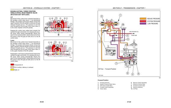
- Color page, page 679
- Color page, page 277
This is a service manual
Here's how it compares to the other manual types.
Service manual
Factory repair procedures and technical information such as specifications, troubleshooting, and wiring and hydraulic diagrams, for the models and systems the manual covers. See What's inside for its topics.
Operator's manual
Safe operation, controls, maintenance schedules, lubrication points, inspections, and basic checks. Repair procedures are in the service manual.
Parts manual
Illustrated diagrams with factory part numbers for identifying components and ordering parts. Repair procedures are in the service manual.
Engine service manuals are sometimes sold separately, since certain machine models were offered with more than one engine option.
What it's used for
Factory manual for in-house farm and construction shop use. Straightforward, complete, and easy to follow. It contains the OEM information dealership service departments and parts counters use to diagnose problems, identify components, and perform maintenance or repairs correctly.
Service shops and owner/operators who repair their own equipment
Identifying correct parts and seeing how assemblies come apart and go back together
Keeping equipment running with less downtime
Factory manual, 1,423 pages
Quantity one is the manual described above.
Fast free USA shipping
Ships in 1 business day.
60-day returns
Free if the mistake is ours. A manual ordered in error must come back unopened in its shrink-wrap; you pay return shipping and a 20% restocking fee applies. Return policy
Binder not included
Manuals over about 300 pages may need a standard 3-ring binder, which you can buy locally to keep the pages organized for shop use.
Questions about model, serial number, engine coverage or contents? Contact us before purchasing and we'll help confirm it's the right manual. Please verify the manual type, machine model, serial number range and engine coverage before purchasing: manuals ordered in error carry a 20% restocking fee (return policy).