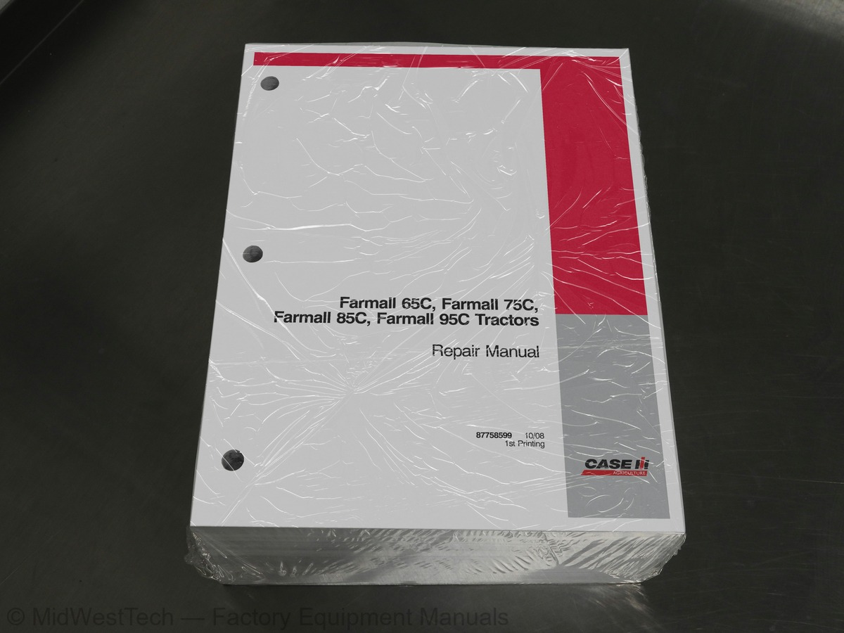
Case Farmall 65C, 75C, 85C, 95C Tractor Service Manual
1,695 pages · Publication 87758598
Added to your cart. View cart
- Models
- Farmall 65C, 75C, 85C, 95C
- Manual type
- Service Manual
- Pages
- 1,695
- Publication
- 87758598
- Condition
- Brand new
What's inside
From the manual's own table of contents: 116 sections, 671 entries. See sample pages (PDF, 642 KB)
Description and Operation1 topic
- Exhaust Gas Recirculation System (EGR)
Overhaul 0.6.05 topics
- Installation
- Removing the Crankshaft Front Seal
- Engine Assembly on the Bench
- Pre-Heating System and Tappet Cover
- Fitting the Starter Motor
Checks, Measurements and Repairs19 topics
- Crankcase, Cylinder Liners
- Checks and Measurements
- Connecting Rods
- Checking Connecting Rods
- Checking TWisting
- Measuring the Piston Diameter
- Piston PINS
- Conditions for Correct Pin-piston Coupling
- Measuring the Clearance X of the V-Ring
- Camshaft 0.0.0
- Checking Cam Lift and Pin Alignment
- Cylinder Head
- Checking the Cylinder Head Mating Surface
- Cylinder Head Thickness
- Cylinder Head Hydraulic Seal Check
- Functional Checks
- Oil Filter 0
- Replacement
- Cooling System
Show all 116 sections
10 41410 4-Cylinder Coolant Pump and Generator Drive Belt3 topics
- Installation
- Description and Operation
- Overhaul
18 110 30 Single Disk Clutch 11” (Fitted With Power-shuttle)4 topics
- Checks, Measurements and Repairs
- Dual Disk Clutch 2.0.2.0
- Coplanarity Adjustment of 11”/11” Dual Clutch Release
- Coplanarity of 11” Single Plate Clutch Release Levers
18 100 40 Gear Clutch Control Adjustments3 topics
- PTO Clutch Control Adjustments . 2.0.0
- PTO Clutch Servo Control Adjustment
- Adjusting the PTO Engaged Switch
Rear Transmission-Gearbox Casing2 topics
- Removal
- Installation 00
21118 85 Gearbox Transmission Casing4 topics
- Disassembly
- ASSEMDIy 16
- Transmission-Gearbox Casing
- Gearbox Driving and Driven Shafts End Float Adjustment
21 130 10 Gearbox Control Lever5 topics
- Removal
- Installation 0.0
- Installation
- Installation 0.0
- Troubleshooting
21 160 31 Splitter Device and Creeper Unit Gearbox, Shafts and Bearings1 topic
- Power Shuttle Unit
21118 85 Gearbox Transmission Casing1 topic
- Disassembly-Assembly
21 134 46 Power Shuttle Control Valve3 topics
- Disassembly
- ASSEMbly 2
- Disassembly
21 134 70 Control Valve Solenoid with Respect to Clutches2 topics
- Removal
- Installation 00
21 134 70 Control Valve Solenoid with Respect to Gearbox6 topics
- Removal
- Installation 0.0
- Disassembly - Assembly
- Clutch Control Pressure Test
- Drive Gear
- Troubleshooting
42 23 101 Drive Gear HOUSING3 topics
- Disassembly
- ASSEMbIy 2
- Installation
25 100 30 Front Axle Assembly2 topics
- Removal
- Installation
25 104 34 Front Differential Lock Clutch Unit3 topics
- Overhaul with Unit Removed
- Bevel Drive Adjustments
- LIM-Slip Self-locking Differential Lock
Description and Operation1 topic
- Hydraulically Controlled Rear Differential Lock
27 106 16 Rear Transmission Gearbox1 topic
- Disassembly
27 110 10 Adjusting the Position of Differential Lock Engagement Sleeve5 topics
- Adjusting the Bevel Gear Pair
- Clearance Between the Sides of the Bevel Drive Teeth
- Adjustment of the Clearance Between the Sun and Planet Pinion Teeth
- Removal
- Installation 0.0
27 120 32 Epicyclic Final Drive6 topics
- Removal - Installation
- Special Tools
- Description and Operation
- Mechanical PTO
- Troubleshooting . 0.0
- Overhaul 0.6
Description and Operation1 topic
- Park Brake
33 202 60 Right or Left Hand Brake2 topics
- Removal
- Installation
33 202 46 Brake Hydraulic PUMP6 topics
- Removal
- Installation
- Service BrakeS 2.0.0
- Control Pedals Stroke Adjustment (Tractors With Cabs)
- Removal
- Installation 0.0
33 110 08 Handbrake Control4 topics
- Stroke Adjustment
- Adjusting the Parking Brake ON Switch
- Special Tools
- Troubleshooting . 0.0
35 110 08 Rod Mechanism Adjustments1 topic
- Limit of the Fast Raise/Lower Device
Description and Operation7 topics
- Operating Stages of Auxiliary Control Valve for Operation of a Double-acting Cylinder
- Operating Stages of Auxiliary Control Valve for Operation of a Single-acting Cylinder
- Cylinder with Automatic Detent Release and Float
- Lowering
- Cylinder with Automatic Detent Release and Float
- Removal
- Installation 0
35 204 46 Auxiliary Control Valves 2.0.04 topics
- Disassembly - Assembly (with the Unit Removed)
- Convertible Single/Double Acting Auxiliary Control Valve
- Valve Leakage TeSt 0.0
- Adjustment of the Automatic Detent Release Pressure
Description and Operation4 topics
- Electronically Controlled Hydraulic Lift Operation
- Neutral Phase
- Lifting Phase 0.0.0
- Lowering Phase
35 110 30 Electronically Controlled Hydraulic Lift2 topics
- Removal
- Installation
35 110 53 Draft Sensor Support2 topics
- Removal - With Lift Removed
- Installation - With Lift Removed
35 130 30 Lift Electronic Control Center2 topics
- Removal
- Installation
35 130 36 Lift Arm Potentiometer6 topics
- Installation
- Removal-Installation
- Cylinder Safety Valve Calibration
- Control Valve Block Pin
- ASSEMDIy 2.2
- Overhaul 2
35 104 30 Lift Oil Pump - w/Pump Removed16 topics
- Sectional VieWS
- Description and Operation
- Front Mechanical Lift
- Front Electronic Lift
- Lift Arm Down Speed Control Potentiometer
- Lift Arm Up Limit Control Potentiometer
- Working Depth Control Potentiometer
- Pressure/Mixed/Position Control Potentiometer
- Lift Arm Up/Down Switch on the Dashboard
- Lift Arm Up/Down Switches on the Right-Hand Mudguard
- External Lift Arm Up/Down Switches
- Lift Arms Position Sensor
- Accumulator Control Valve .. 2.0.0.6. e cece eet eee e eee ee eeeeeeee
- Neutral Phase
- Lifting Phase
- Lowering Phase
Troubleshooting4 topics
- Front Electronic Lift Operating Instructions
- Position Control 20
- Pressure Test
- Smooth Ride Control
Calibration2 topics
- Implement Weight Calibration
- Calibrating The Lift Arms Height Sensor
35 160 40 Front Electronic Lift Control Valve2 topics
- Fault Code Indication
- Fault Code Decoding
41 204 10 Hydrostatic Steering Wheel2 topics
- Removal
- Installation
41 204 34 Hydrostatic Steering Control Valve - W/Control Valve Removed5 topics
- Disassembly
- ASSEMDIy 2.0
- With Control Valve Installed on Tractor
- Description and Operation
- Overhaul (A 31 XRP 2 Pump Model)
Overhaul5 topics
- Disassembly
- Assembly 1
- Installation
- Removal
- Installation
44 511 80 Checking The Alignment of the Leading Wheels7 topics
- Description of Operation
- Simplified Psychrometric Diagram
- Main Components of Cab Air Conditioning System
- Heating 0.0
- Ignition SWitCh 2
- Cab Air Conditioning and Temperature Controls
- Use of the Air Conditioning System
50 200 03 Function and Cooling Testing8 topics
- Pressure Variations At Different Altitudes
- Maintenance of the Air Conditioning System
- Warnings for Air Conditioning System Repair Operations
- Air Conditioning System Fault Diagnosis Summary
- Visual Inspection of Components
- Refrigerant Recovery-recycling and Evacuation-charging Stations
- Recovery and Recycling Station (294048)
- Recycling, Evacuation and Charging Station (380000315)
50 200 04 Drying, Recharging and Refrigeration Check8 topics
- Recovery/ Recycling Station 294048
- Recycling of Recovered Refrigerant
- the Recycling, Evacuation and Charging Station 380000315
- Evacuation of the Graduated Cylinder (31) of the Evacuation/Charging Station
- Charging the Graduated Cylinder (31) of the Evacuation/Charging Station
- Discharged Using the Recovery/Recycling Station)
- Charging the Cab Air Conditioning System (After Evacuation) with New Oil
- Summary of the Air Conditioning System Charging Operations
50 200 06 Checking for and Removing Gas LeakS2 topics
- Checking for Refrigerant Leaks Using an Electronic Leak Detector
- Refrigerant Gas Leak Test
50 200 10 Compressor Drive Belt Tension Adjustment1 topic
- Checking Compressor Drive Belt Tension
50 206 56 Cab Air Conditioning System Evaporator Unit17 topics
- LH Digital Display
- RH Digital Display
- Engine Coolant Temperature Gauge
- Fuel Gauge
- Multifunction Display 2.0.0
- Controls On Right-hand Cab Upright
- Replacing The Front Side, and Indicator Light Bulbs
- Replacement (Version Without Cab)
- Lamp Bulb Replacement Cab Front and Rear Work Lights
- Rear Sidelights, Brake And Direction Indicator Light Bulbs
- Replacing the Courtesy Light and Adjustable Reading Light
- Courtesy Light
- Adjustable Reading Lamp
- Work Light Bulb Replacement
- Replacing Electronic Lift Unit Control Indicator Lights
- System TestS 00
- Bench Tests 00
System Testing and Troubleshooting80 topics
- Preliminary Checks
- Alternator Wire Connection Tests
- Charging Circuit Voltage Drop Tests
- Alternator Component Tests
- Rotor and Regulator Field Circuit Test
- Checking the Continuity of Three Stator Windings
- Checking the Diodes
- Energizing Diode Test
- Positive Power Diode Tests
- Negative Power Diode Tests
- Pins Connected to Brushes
- Electronic Voltage Regulator
- Inductor Winding Insulation Test
- Repair
- Battery Maintenance
- Component List - Numeric Order
- List of Relay Functions
- Main Fusebox
- Maxi-fUSCS 20
- Electrohydraulic Differential Lock and Mechanical Lift
- List of Relay Functions
- Main FUSCD0X 0
- Maxi-fUSCS 00
- Electrohydraulic Differential Lock and Electronic Lift
- List of Relay Functions
- Main Fusebox
- Maxi-fUS€S 2.0
- Electrohydraulic Differential Lock and Mechanical Lift
- List of Relay Functions
- Main Fusebox
- Electronic Rear Lift And Electrohydraulic Differential Lock
- List of Relay Functions 1.0.00
- Main Fusebox
- Maxi-fFUSES 6.6
- Fuse and Relay Layout on Cab Right-hand Upright
- Air Conditioned Cab Relays (2) 1.0
- Heated Cab Relays (2) 0.0
- Fuse Layout
- Fuse Box (1) (Cab Circuit) 2.0
- Power SocketS
- Grid Heater 2.0
- Electronic Flasher Module
- Electrical Circuits 0.2
- How to Use the Wiring Diagrams
- Wire Color Coding
- Electrical Circuit Components (Functional Order)
- Version INdexX 26
- Version 1 - 2WD Models, Electrohydraulic Differential Lock, Rear Mechanical Lift
- Electrical Circuits Components Version 1.1.0.0
- Circuit Diagrams .. 0.6.6.6 cence eee e nett tetera eeees
- Component Locations - Diagrams 1 through 4
- Power Sockets, Wiper/Washer Pumps Circuit - Diagram 2
- Brakes, Brake Lights, Differential Lock Circuit - Diagram 3
- (Control Switches and Flasher) - Diagram 4
- Component Locations - Diagrams 5 through 7
- Grid-heater Circuit - Diagram 5.2.0
- Instrument and Sensor Circuit - Diagram 6
- Power Take-off and Safety Device Circuit - Diagram 7
- Component Locations - Diagrams 8 through 11. «1.2
- Seven-pin Socket and Number Plate Light Circuit - Diagram 8
- External Lights and Horn Circuit - Diagram 9
- Power Supplies 1 Circuit - Diagram 10 1.6
- Power Supplies 2 Circuit - Diagram 11.0
- Trailer Brake Circuit - Diagram 12 «2.0
- Engine, Sensors and Transmitters Circuit - Diagram 13
- Safety and Speed Sensors Circuit - Diagram 14
- Intermediate Connections Circuit - Diagram 15.1.6
- Component Locations - Diagrams 16 through 21
- Cab Ventilation and Air-conditioning Circuit - Diagram 16
- Rotating Beacon Circuit - Diagram 17 «2
- Supplementary Direction Indicator Lights and Radio Circuit - Diagram 18
- Cab Power Supplies Circuit - Diagram 19 1.0
- Wiper/Washer Circuit - Diagram 20
- Work Lights Circuit - Diagram 21 2.00
- Component Locations - Diagrams 22 through 26
- Power Shuttle Circuit 8+8 / 16+16 (Dashboard Side) - Diagram 22
- Power Shuttle Circuit (Transmission Side) - Diagram 23
- Power Shuttle Circuit 32+16 / 44+16 (Dashboard Side) - Diagram 24
- Power Shuttle Circuit (Transmission Side) - Diagram 25
- Front PTO Circuit - Diagram 26 «1.2
Lock, Rear Mechanical Lift103 topics
- Circuit Index 2.6
- Electrical Circuits Components Version 2
- Component Locations - Diagrams 1 through 4
- Four-wheel Drive Circuit - Diagram 1 oo
- Battery Cut-out Circuit - Diagram 2 2.0.6
- Power Sockets, Wiper/Washer Pumps Circuit - Diagram3
- Brakes, Brake Lights, Differential Lock Circuit - Diagram 4
- Component Locations - Diagrams 5 through 8
- Diagram 5 2
- Grid Heater Circuit - Diagram 6 «1.0
- Instrument and Sensor Circuit - Diagram 7 «0.2
- Power Take-off and Safety Device Circuit - Diagram 8
- Component Locations - Diagrams 9 through 12
- Seven-pin Socket and Number Plate Light Circuit - Diagram9
- External Lights and Horn Circuit - Diagram 10
- Power Supplies 1 Circuit - Diagram 11.0.2
- Power Supplies 2 Circuit - Diagram 12.1.2
- Component Locations - Diagrams 13 through 15 «1.6
- Engine, Sensors and Transmitters Circuit - Diagram 13
- Intermediate Connections Circuit - Diagram 14
- Trailer Brake Circuit - Diagram 15 6
- Component Locations - Diagram 16 through 21
- Cab Ventilation and Air-conditioning Circuit - Diagram 16
- Rotating Beacon Circuit - Diagram 17 1.0
- Supplementary Direction Indicator Lights and Radio Circuit - Diagram 18
- Cab Power Supplies Circuit - Diagram 19
- Wiper/Washer Circuit - Diagram 20.0.0
- Work Lights Circuit - Diagram 21 «1
- Component Locations - Diagrams 21 through 27
- Power Shuttle Circuit 8+8 / 16+16 (Dashboard Side) - Diagram 22
- Power Shuttle Circuit (Transmission Side) - Diagram 23
- Power Shuttle Circuit 32+16 / 44+16 (Dashboard Side) - Diagram 24
- Power Shuttle Circuit (Transmission Side) - Diagram 25
- Front PTO Circuit - Diagram 26 «0.0
- Digital Instrument Circuit - Diagram 27 2.0
- Differential Lock, Rear Electronic Lift
- Circuit Index . 6
- Electrical Circuits Components Version 3
- Component Locations - Diagrams 1 through 4
- Battery Cut-out Circuit - Diagram 2 2.0.6
- Power Sockets, Wiper/Washer Pumps Circuit - Diagram 3
- Brakes, Brake Lights, Differential Lock Circuit - Diagram 4
- Component Locations - Diagrams 5 through 8
- Front and Rear Electronic Lift Circuit - Diagram 5
- Grid Heater Circuit - Diagram 6.1.0
- Power Take-off and Safety Device Circuit - Diagram 8
- (Control Switches and Flasher) - DiagraM9
- External Lights and Horn Circuit - Diagram 10
- Power Supplies 1 Circuit - Diagram 11 2
- Power Supplies 2 Circuit - Diagram 12 2.0
- Seven-pin Socket and Number Plate Light Circuit - Diagram 13
- Component Locations - Diagrams 14 through 17 «0.0.0
- Intermediate Connections Circuit - Diagram 14.1.0
- Trailer Brake Circuit - Diagram 15 2.0
- Diagnostics Connection Can Line Circuit - Diagram 16
- Engine, Sensors and Transmitters Circuit - Diagram 17
- Component Locations - Diagrams 18 through 23
- Cab Ventilation and Air-conditioning Circuit - Diagram 18
- Supplementary Direction Indicator Lights and Radio Circuit - Diagram 20
- Cab Power Supply Circuit - Diagram 21 1.0
- Wiper/Washer Circuit - Diagram 22
- Work Lights Circuit - Diagram 23
- Component Locations - Diagrams 24 through 28
- Power Shuttle Circuit 8+8 / 16+16 (Dashboard Side) - Diagram 24
- Power Shuttle Circuit (Transmission Side) - Diagram 25
- Power Shuttle Circuit 32+16 / 44+16 (Dashboard Side) - Diagram 26
- Power Shuttle Circuit (Transmission Side) - Diagram 27
- Front PTO Circuit - Diagram 28 «0.6
- Digital Instrument Circuit - Diagram 29
- Lock, Rear Mechanical Lift
- Electrical Circuits Components Version 4
- Component Locations - Diagrams 1 through 4
- Four-wheel Drive Circuit - Diagram 1.2.6
- Battery Cut-out Circuit - Diagram 2 6.0.0
- Power Sockets, Wiper/Washer Pumps Circuit - Diagram 3
- Brakes, Brake Lights, Differential Lock Circuit - Diagram 4
- Component Locations - Diagrams 5 through 8
- (Control Switches and Flasher) - Diagram 5
- Grid Heater Clrcuit - Diagram 6 2.0.6
- Instrument and Sensor Circuit - Diagram 7 «0.2.0
- Power Take-off and Safety Device Circuit - Diagram 8
- Component Locations - Diagrams 9 through 12.2.0
- Seven-pin Socket and Number Plate Light Circuit - Diagram9
- External Lights and Horn Circuit - Diagram 10
- Power Supplies 1 Circuit - Diagram 11.0
- Power Supplies 2 Circuit - Diagram 12.0.2
- Component Locations - Diagrams 13 through 16
- Trailer Brake Circuit - Diagram 13 6.0
- Intermediate Connections Circuit - Diagram 14
- Engine, Sensors and Transmitters Circuit - Diagram 15
- Diagnostics Connection Can Line Circuit - Diagram 16
- Component Locations - Diagrams 17 through 23
- Cab Ventilation and Air-conditioning Circuit - Diagram 17
- Rotating Beacon Circuit - Diagram 18.0
- Supplementary Direction Indicator Lights and Radio Circuit - Diagram 19
- Wiper/Washer Circuit - Diagram 21
- Work Lights Circuit - Diagram 22
- Power Shuttle Circuit 8+8 / 16+16 (Dashboard Side) - Diagram 23
- Component Locations - Diagrams 24 through 27
- Power Shuttle Circuit (Transmission Side) (Diagram 24)
- Power Shuttle Circuit 32+16 / 44+16 (Dashboard Side) - Diagram 25
- Power Shuttle Circuit (Transmission Side) - Diagram 26
- Front PTO Circuit - Diagram 27 «0.0
Rear Electronic Lift47 topics
- Circuit Index
- Electrical Circuits Components Version 5
- Component Locations - Diagrams 1 through 4
- Four-wheel Drive Circuit - Diagram 1 oo
- Battery Cut-out Circuit - Diagram 2 «2.0
- Power Sockets, Wiper/Washer Pumps Circuit - Diagram 3
- Component Locations - Diagrams 5 through 8
- Front and Rear Electronic Lift Circuit - Diagram 5
- Grid Heater Circuit - Diagram 6.2.0
- Component Locations - Diagrams 9 through 13
- External Lights and Horn Circuit - Diagram 10
- Power Supplies 1 Circuit - Diagram 11.0
- Power Supplies 2 Circuit - Diagram 12.0.0
- Diagnostics Connection Can Line Circuit - Diagram 14
- Trailer Brake Circuit - Diagram 15 61
- Intermediate Connections Circuit - Diagram 16
- Engine, Sensors and Transmitters Circuit - Diagram 17
- Component Locations - Diagrams 18 through 23
- Cab Ventilation and Air-conditioning Circuit - Diagram 18
- Rotating Beacon Circuit - Diagram 19.0.6
- Supplementary Direction Indicator Lights and Radio Circuit - Diagram 20
- Cab Power Supply Circuit - Diagram 21 «0.0.0
- Windscreen and Rear Window Washer/Wiper Circuit - Diagram 22
- Work Lights Circuit - Diagram 23
- Component Locations - Diagrams 24 through 28
- Power Shuttle Circuit 8+8 / 16+16 (Dashboard Side) - Diagram 24
- Power Shuttle Circuit (Transmission Side) - Diagram 25
- Power Shuttle Circuit 32+16 / 44+16 (Dashboard Side) - Diagram 26
- Power Shuttle Circuit (Transmission Side) - Diagram 27
- Front PTO Circuit - Diagram 28 «0.0
- Description 2.2
- List of Relay Functions
- Four-wheel Drive And Mechanical Lift
- List of Relay Functions 0.0.0.0
- Main Fusebox
- Maxi-fFUSES 6.6
- Electrohydraulic Differential Lock
- List of Relay Functions
- Main Fusebox
- Maxi-fUSES 6
- Power SocketS
- Seven-pole Power Socket
- A Two-pole Power Socket (ISO Version)
- A Power Socket (North America Version)
- Electronic Flasher Module
- Ground Location Points
- Ground Points Layout
Electrical Circuits 2.0.0.076 topics
- How To Use the Wiring Diagrams
- Connector Code Reading
- Wire Color Coding
- Electrical Circuits Components Version 1
- Component Locations - Diagrams 1 through 4
- Four-wheel Drive Circuit - Diagram 1.2.6
- Grid Heater Circuit - Diagram 2 2.0
- Power Socket Circuit - Diagram 3.1.6
- Brakes, Brake Lights, Differential Lock Circuit - Diagram 4
- Component Locations - Diagrams 5 through 7
- External Lights and Horn Circuit - Diagram 6.1.2.0
- Power Supplies 1 Circuit - Diagram 7 1.0.0
- Component Locations - Diagram 8 through 11. 0
- Instrument and Sensor Circuit - Diagram 8 «0.6
- Power Take-off and Safety Device Circuit - Diagram 9
- Seven-pin Socket and Number Plate Light Circuit - Diagram 10
- Safety and Speed Sensors, Rear Work Light Circuit - Diagram 11
- Component Locations - Diagrams 12 through 14
- Trailer Brake Circuit - Diagram 12
- Power Supplies 2 Circuit - Diagram 13.1
- Engine, Sensors and Transmitters Circuit - Diagram 14
- Power Shuttle Circuit 8+8 / 16+16 (Dashboard Side) - Diagram 15
- Power Shuttle Circuit (Transmission Side) - Diagram 16
- Power Shuttle Circuit 32+16 / 44+16 (Dashboard Side) - Diagram 17
- Power Shuttle Circuit (Transmission Side) - Diagram 18
- Front PTO Circuit - Diagra€M 19 1.6
- Circuit Index . 0
- Electrical Circuits Components Version 2
- Component Locations - Diagrams 1 through 4
- Four-wheel Drive Circuit - Diagram 1.1
- Power Take-off and Safety Device Circuit - Diagram 2
- Power Socket Circuit - Diagram 3 2.6
- Grid-Heater Circuit - Diagram 6 1.0
- Power Supplies 1 Circuit - Diagram 7 «0.0
- Power Supplies 2 Circuit - Diagram 8
- Instrument and Sensor Circuit - Diagram 9 1.1
- Component Locations - Diagrams 10 and 11.0.0
- External Lights and Horn Circuit - Diagram 10
- Safety and Speed Sensors, Rear Work Light Clrcuit - Diagram 11
- Component Locations - Diagrams 12 through 14
- Engine, Sensors and Transmitters Circuit - Diagram 12
- Seven -pin Socket and Number Plate Light Circuit - Diagram 13
- Trailer Brake Circuit - Diagram 14 10
- Component Locations - Diagrams 15 through 20
- Power Shuttle Circuit 8+8 / 16+16 (Dashboard Side) - Diagram 15
- Power Shuttle Circuit (Transmission Side) - Diagram 16
- Power Shuttle Circuit 32+16 / 44+16 (Dashboard Side) - Diagram 17
- Power Shuttle Circuit (Transmission Side) - Diagram 18
- Front PTO Circuit - Diagram 19.0
- Digital Instrument Circuit - Diagram 20
- Rear Mechanical Lift
- Circuit Index . 6
- Electrical Circuits Components Version 3
- Component Locations - Diagrams 1 through 4
- Four-wheel Drive Circuit - Diagram 1 oo
- Power Socket Circuit - Diagram 2.1.0.0
- Brakes, Brake Lights, Differential Lock Circuit - Diagram3
- Component Locations - Diagrams 5 through 8
- Grid-heater Circuit - Diagram 5 2.0
- Instrument and Sensor Circuit - Diagram 6
- Power Take-off and Safety Device Circuit - Diagram 7
- Seven-pin Socket and Number Plate Light Circuit - Diagram 8
- Component Locations - Diagrams 9 through 13 «1.2
- External Lights and Horn Circuit - Diagram 9
- Power Supplies 1 Circuit - Diagram 10
- Power Supplies 2 Circuit - Diagram 11 2.0
- Trailer Brake Circuit - Diagram 12 «2.0.0
- Intermediate Connections Circuit - Diagram 13
- Component Locations - Diagrams 14 and 15.1.0
- Engine, Sensors and Transmitters Circuit - Diagram 14
- Diagnostics Connection Can Line Circuit - Diagram 15
- Component Locations - Diagrams 16 through 20
- Power Shuttle Circuit 8+8 / 16+16 (Dashboard Side) - Diagram 16
- Power Shuttle Circuit (Transmission Side) - Diagram 17
- Power Shuttle Circuit 32+16 / 44+16 (Dashboard Side) - Diagram 18
- Power Shuttle Circuit (Transmission Side) - Diagram 19
MFD Fault Codes15 topics
- H2 - View All Calibration Values (SB- SA) 1.0.20
- Clutch Calibration Values (SB)
- Lift Calibration Values (SA)
- Options for Control Panel (ZA)
- Automatic Mfd Options (SC)
- H4 - Software Revision Levels
- Software Revision Level of the Control Panel (ZA)
- Software Revision Level of the Automatic Mfd Control Unit (SC)
- Software Revision Level of the Power Shuttle Control Unit (SB)
- Software Revision Level of the Rear Lift Control Unit (SA)
- Control Switches Diagnostics of the Control Panel (ZA)
- Automatic Mfd Switches Diagnostics (SC)
- Power Shuttle Switches Diagnostics (SB)
- Electronically Controlled Rear Lift Switches Diagnostics (SA)
- H7 - Service Procedures (SB - SA) 1.0
H8 - Deletion of Stored Data (ZA - SC - SB- SA)8 topics
- Deletion of Stored Data In the Control Panel (ZA)
- Deletion of Stored Data for Automatic Mfd (SC)
- Deletion of Stored Data for Power Shuttle (SB)
- Deletion of Stored Data for Electronically Controlled Rear Lift (SA)
- Control Panel Voltmeter (ZA) . 0
- Automatic Mfd Voltmeter (SC)
- Power Shuttle Voltmeter (SB)
- Electronically Controlled Rear Lift Voltmeter (SA)
HB - Displays Stored Error Codes (ZA - SC - SB - SA)3 topics
- Displays the Error Codes Stored In the Control Panel (ZA)
- Displays the Error Codes Stored In the Mfd Control Unit (SC)
- Control Unit (SB) 2.0
HC - Deletes All the Stored Error Codes (ZA- SC - SB- SA)3 topics
- Deletes All the Stored Error Codes (SC)
- Deletes All the Stored Error Codes (SB)
- Deletes All the Stored Error Codes (SA)
HF - Displays the Hardware Information (ZA - SC - SB- SA)5 topics
- Displays the Hardware Information (SC)
- Displays the Hardware Information (SB)
- Diagram 1 - Transmission Side Front Lift Circuit
- Diagram 2 - Front Side Front Lift Circuit
- Diagram 3 - Cab Side Front Lift Circuit 0.0.00
90 150 10 Cab With Platform Assembly2 topics
- Removal
- Installation
90 160 16 RH or LH Upright Seals13 topics
- Removal
- Installation 0.0
- Removal
- Installation
- General Instructions
- Health and Safety
- Precautionary Statements
- Safety
- Ecology and the Environment
- Minimum Hardware Tightening Torques
- Federal Emissions Warranty
- California Emission Control Warranty Statement
- Consumables
Inside this manual
Real pages from this service manual (1,695 pages). Open the sample pages (PDF, 641 KB)

- Specifications, page 382: SECTION 27 -- REAR AXLE MECHANICAL TRANSMISSION -- CHAPTER 1
- Repair procedure, page 538: SECTION 35 -- HYDRAULIC SYSTEMS -- CHAPTER 4
- Diagram, page 1,370: SECTION 55 -- ELECTRICAL SYSTEM -- CHAPTER 8
- Color page, page 246: SECTION 21 -- GEAR TRANSMISSION -- CHAPTER 1
- Color page, page 496: SECTION 35 -- HYDRAULIC SYSTEMS -- CHAPTER 2
- Foldout diagram, page 978: SECTION 55 -- ELECTRICAL SYSTEM -- CHAPTER 6
Other manuals for this machine
Save 10% on 2 manuals, 15% on 3 or more. Other manuals are listed below. Editions cover different serial number ranges: check the serial coverage and tick only the ones that match your machine.
Added to your cart. View cart
This is a service manual
Here's how it compares to the other manual types.
Service manual
Factory repair procedures and technical information such as specifications, troubleshooting, and wiring and hydraulic diagrams, for the models and systems the manual covers. See What's inside for its topics.
Operator's manual
Safe operation, controls, maintenance schedules, lubrication points, inspections, and basic checks. Repair procedures are in the service manual.
Parts manual
Illustrated diagrams with factory part numbers for identifying components and ordering parts. Repair procedures are in the service manual.
Engine service manuals are sometimes sold separately, since certain machine models were offered with more than one engine option.
What it's used for
Factory manual for in-house farm and construction shop use. Straightforward, complete, and easy to follow. It contains the OEM information dealership service departments and parts counters use to diagnose problems, identify components, and perform maintenance or repairs correctly.
Service shops and owner/operators who repair their own equipment
Identifying correct parts and seeing how assemblies come apart and go back together
Keeping equipment running with less downtime
Factory manual, 1,695 pages
Quantity one is the manual described above.
Fast free USA shipping
Ships in 1 business day.
60-day returns
Free if the mistake is ours. A manual ordered in error must come back unopened in its shrink-wrap; you pay return shipping and a 20% restocking fee applies. Return policy
Binder not included
Manuals over about 300 pages may need a standard 3-ring binder, which you can buy locally to keep the pages organized for shop use.
Other editions and similar models
Questions about model, serial number, engine coverage or contents? Contact us before purchasing and we'll help confirm it's the right manual. Please verify the manual type, machine model, serial number range and engine coverage before purchasing: manuals ordered in error carry a 20% restocking fee (return policy).