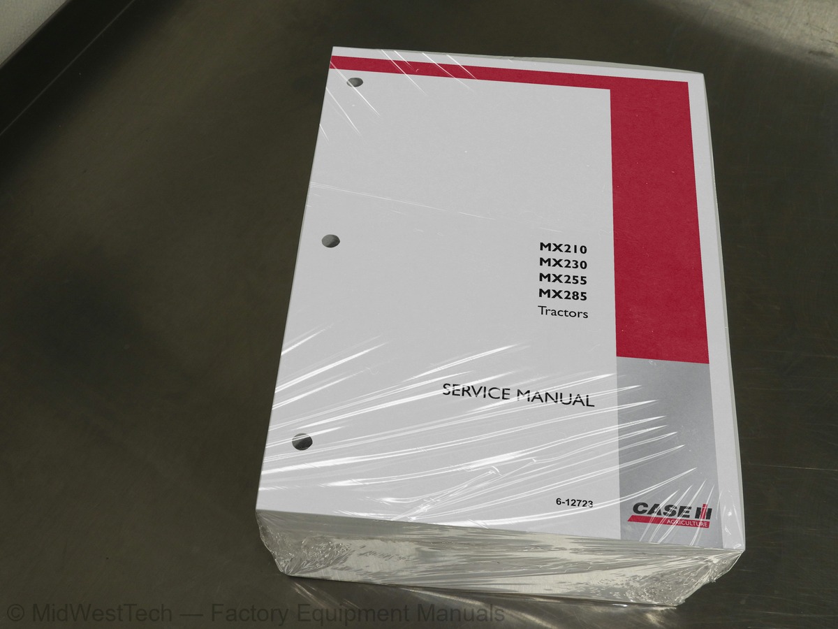
Case MX210, MX230, MX255, MX285 Tractor Service Manual
2,307 pages · Publication 6-12723
Added to your cart. View cart
What's inside
From the manual's own table of contents: 480 topics. See sample pages (PDF, 994 KB)
- SAFETY
- GENERAL INFORMATION
- Cleaning
- Inspection
- Bearings
- Needle Bearings
- Gears
- Oil Seals, O-rings and Gaskets
- Shafts
- Service Parts
- Lubrication
- MAINTENANCE SCHEDULE
- GENERAL SPECIFICATIONS
- Fluid Capacities and Types
- Hydraulic Specifications
- Electrical Specifications
- Cab Fuse Identification and Amperage
- Cab Relay Identification (Facing Rear Window)
- Engine Compartment Fuse/Relay Identification (Power Distribution Box)
- Lamps and Bulbs
- Accessory Connectors
- Air Conditioner System Specifications
- Engine Specifications
- Transmission Specifications
Show all 480 topics
- Hitch Specifications
- SPECIAL TORQUES
- FUEL TANK
- General
- Removal
- Installation
- SPECIAL TOOLS
- FUSES AND RELAY IDENTIFICATION
- Cab Fuses/Relay Location
- Fuse Identification
- Relays
- INSTRUMENTATION AND CONTROLS
- CONNECTOR AND COMPONENT LOCATIONS
- ELECTRICAL CONNECTORS
- ELECTRICAL SYSTEMS SCHEMATICS AND DIAGNOSTICS
- Power Distribution System Circuit Operation
- Power Distribution Circuit Troubleshooting
- Power Distribution Schematic
- POWER DISTRIBUTION SYMPTOM CHART
- Diagnostic Tests
- AUDIO SYSTEM
- Audio System Circuit Operation
- Audio System Circuit Troubleshooting
- Audio System Symptom Chart
- Audio System Diagnostic Tests
- CHARGING SYSTEM
- Charging System Circuit Operation
- Charging System Circuit Troubleshooting
- Charging System Symptom Chart
- Charging System Diagnostic Tests
- EXTERIOR LIGHTING SYSTEM
- Exterior Lighting System Circuit Operation
- Exterior Lighting System Circuit Troubleshooting
- Exterior Lighting System Symptom Chart
- Exterior Lighting System Diagnostic Tests
- INSTRUMENTATION AND WARNING SYSTEM
- Instrumentation and Warning System Circuit Troubleshooting
- Instrumentation and Warning System Symptom Chart
- Instrumentation and Warning System Diagnostic Tests
- INTERIOR LIGHTING AND HORN SYSTEM
- Interior Lighting and Horn System Circuit Operation
- Interior Lighting and Horn System Circuit Troubleshooting
- Interior Lighting and Horn System Symptom Chart
- Interior Lighting and Horn System Diagnostic Tests
- STEERING COLUMN AND STEERING HAND PUMP
- Steering Hand Pump Service
- STEERING COLUMN ASSEMBLY
- TRANSMISSION SYSTEM INTRODUCTION
- TRANSMISSION SYSTEM CONTROLS
- TRANSMISSION SYSTEM COMPONENTS
- TRANSMISSION LUBE AND DISTRIBUTION TUBES
- MX MAGNUM POWERSHIFT TRANSMISSION CLUTCH LAYOUT
- POWERSHIFT VALVE CLUTCH ENGAGEMENTS
- MX MAGNUM
- Powershift Transmission Clutch Layout with Pump Drive, PTO, MFD, and Creeper Drive
- POWER FLOW (REVERSE SPEEDS)
- POWER FLOW (FORWARD CREEPER DRIVE SPEEDS)
- POWER FLOW (REVERSE CREEPER DRIVE SPEEDS)
- INCHING VALVE OPERATION
- TRACTOR MONITOR - TRANSMISSION LEAKAGE CHECK
- MASTER CLUTCH PRESSURE CHECK
- TRANSMISSION INPUT SHAFT AND DRIVE PLATE
- INPUT DROP BOX
- DISASSEMBLY
- Input Gear Removal
- Output Gear Assembly Removal
- Idler Gear Removal
- Input Drop Box Assembly
- Idler Gear Installation
- Output Gear Installation
- Input Gear Installation
- Tubing Installation
- ENGINE FRAME AND DROP BOX SPLIT
- SPEED TO RANGE TRANSMISSION SPLIT
- PICTORIAL INDEX - SPEED TRANSMISSION
- SPECIFICATIONS
- TROUBLESHOOTING AFTER SPEED TRANSMISSION REPAIR
- SPEED TRANSMISSION WITH CREEP OPTION
- For Transmissions With Creep Option
- Countershaft, Input Shaft, and Output Shaft Removal for Transmissions without Creep
- Disassembling the Countershaft with Creeper Speed Clutch
- Disassembling the Countershaft with the Creeper Speed Clutch
- Alternative Method for Snap Ring Removal
- ASSEMBLING THE COUNTERSHAFT WITH CREEPER SPEED CLUTCH
- Countershaft with Creep
- Disassembly and Assembly of Countershaft without Creep
- Disassembling the Speed Input Shaft
- Speed Input Shaft Assembly
- Assembly of the Speed Input Shaft
- Speed Input Shaft
- Disassembling the Speed Output Shaft
- Speed Output Shaft Assembly
- Cross-Section View of Output Shaft
- Air Check for Speed Transmission Clutch Piston Operation
- Countershaft, Input Shaft, and Output Shaft Installation - Exploded View
- Bearing Removal and Replacement
- TRANSMISSION ASSEMBLY WITH CREEP OPTION
- Shafts in Speed Transmission
- TRANSMISSION ASSEMBLY WITHOUT CREEP OPTION
- Input Shaft, and Output Shaft
- RANGE TRANSMISSION TO REAR FRAME SPLIT
- Assembly
- TROUBLESHOOTING AFTER RANGE TRANSMISSION REPAIR
- RANGE TRANSMISSION
- Removing the Shaft Master Clutch
- Removing the Input Shaft, Countershaft, and Mechanical Front Drive (MFD) Clutch Shaft
- Disassembly of the Master Clutch
- Exploded View of the Master Clutch
- Assembly of the Master Clutch
- Disassembly of the Range Transmission Input Shaft
- Exploded View of the Range Transmission Input Shaft
- Assembly of the Range Transmission Input Shaft
- Cross-Section of Input Shaft
- Disassembly of the Range Transmission Countershaft
- Exploded View of the Range Transmission Countershaft
- Assembly of the Range Transmission Countershaft
- Disassembly of the Mechanical Front Drive (MFD) Hub and Input Shaft
- Exploded View of MFD and Park/Emergency Brake
- Assembly of the MFD Clutch
- Assembly of the MFD Input Shaft
- Air Check for Clutch Piston
- Exploded View of the Range Transmission Countershaft, Input Shaft, and MFD Input Shaft
- Housing
- COUNTERSHAFT AND INPUT SHAFT
- Installing the Range Input Master Clutch
- POWERSHIFT TRANSMISSION CONTROL VALVES
- TRANSMISSION CONTROL VALVE CONFIGURATION
- Figure 1 - Transmission Control Valve with Four Solenoids
- Figure 2 - Transmission Control Valve with Four Solenoids
- Figure 3 - Transmission Control Valve with Three Solenoids and Plug
- Figure 4 - Transmission Control Valve with Three Solenoids and Plug
- Figure 5 - Transmission Control Valve with Two Solenoids, Check Valve and Plug
- Figure 6 - Transmission Control Valve with Three Solenoids and Check Valve
- Valve Removal
- Valve Installation
- INCHING VALVE
- Inching Valve Cross Section
- DIFFERENTIAL REMOVAL
- DIFFERENTIAL DISASSEMBLY
- PINION SHAFT
- Removal and Disassembly
- Assembly and Installation
- DIFFERENTIAL ASSEMBLY
- DIFFERENTIAL INSTALLATION
- ADJUSTING THE DIFFERENTIAL PRELOAD
- ADJUSTING THE RING AND PINION BACKLASH
- BEVEL PINION AND GEAR TOOTH CONTACT CHECK
- PUMP DRIVE
- ELECTRONIC MFD CONTROL
- MFD CONTROL MODES
- MFD FUNCTIONAL TESTS
- MFD Valve
- Solenoid Cartridge Valve
- MFD CLUTCH DISENGAGED
- TROUBLESHOOTING
- MFD Clutch Engaged
- WARNING
- DIFFERENTIAL LOCK
- ELECTRONIC DIFFERENTIAL LOCK CONTROL
- DIFFERENTIAL LOCK CONTROL MODES
- DIFFERENTIAL LOCK CONTROL
- DIFFERENTIAL LOCK FUNCTIONAL TESTS
- Differential Lock Valve
- Differential Lock Clutch Disengaged
- Differential Lock Engaged
- PTO/DIFFERENTIAL LOCK VALVE CIRCUIT
- MFD CLUTCH AND OUTPUT SHAFT REMOVAL WITHOUT TRACTOR SPLIT
- MFD Output Shaft Removal
- MFD Output Shaft Disassembly
- MFD Output Shaft Assembly
- MFD Clutch Removal
- MFD Clutch Installation
- MFD DRIVE SHAFT
- MFD Standard Axle
- Suspended MFD Axle
- DIFFERENTIAL CARRIER ASSEMBLY REMOVAL
- Pinion Disassembly
- DIFFERENTIAL CARRIER ASSEMBLY
- Pinion Position and Assembly
- Shim Pack Thickness Chart
- Setting The Pinion Depth
- Adjusting Bearing Preload
- Checking Backlash
- Ring Gear and Pinion Tooth Pattern Interpretation
- Installation of Carrier Assembly to Axle Housing
- REMOVAL OF THE FRONT DIFFERENTIAL CARRIER ASSEMBLY
- REMOVAL OF THE FRONT DIFFERENTIAL FROM THE CARRIER HOUSING
- DISASSEMBLY OF THE DIFFERENTIAL
- ASSEMBLY OF THE DIFFERENTIAL
- REAR AXLE
- AXLE HOUSING DISASSEMBLY
- PLANETARY DISASSEMBLY
- DIFFERENTIAL CARRIER SEAL REPLACEMENT
- PLANETARY ASSEMBLY
- AXLE HOUSING ASSEMBLY
- 4-Inch Axle
- 4-Inch Heavy Duty Axle
- 4.5-Inch Axle
- 4-Inch Standard Axle
- For All Axles
- How To Determine Ram Pressure
- AXLE INSTALLATION
- AXLE SEAL WEAR SLEEVE INSTALLATION (4- Inch Axle Only)
- POWER TAKE OFF
- ELECTRONIC PTO CONTROL
- PTO SYSTEM CONTROL
- PTO CONTROL MODES
- PTO Valve Oil Supply
- PTO Proportional Current Control Solenoid Cartridge Valve
- PTO Clutch Disengaged
- PTO/DIFFERENTIAL LOCK VALVE
- PTO ELECTRICAL CIRCUIT
- PTO Clutch Engaged
- DUAL SPEED 540/1000 RPM PTO
- 1 3/4 INCH 1000 RPM OUTPUT SHAFT
- 1 3/8 Inch 540 RPM Output Shaft
- SINGLE SPEED 1000 RPM PTO
- PLANETARY HUB DISASSEMBLY
- STEERING KNUCKLE AND KINGPIN DISASSEMBLY
- AXLE DRIVE SHAFT DISASSEMBLY
- AXLE SHAFT ASSEMBLY
- KINGPIN ASSEMBLY
- STEERING KNUCKLE ASSEMBLY
- PLANETARY HUB ASSEMBLY
- SUSPENSION MFD AXLE
- Position Sensor Adjustment
- SUSPENDED MFD AXLE OPERATION
- SUSPENDED MFD AXLE- CALIBRATION MODE
- ERROR TABLE
- SUSPENDED MFD AXLE- MANUAL OPERATION MODE (TEST MODE)
- SUSPENDED MFD AXLE- DEMONSTRATION MODE
- BRAKE VALVE
- BRAKE CYLINDERS
- PARK BRAKE
- TRAILER BRAKE SYSTEMS
- HYDRAULIC BRAKE SYSTEMS
- European / NAO Hydraulic Trailer Brakes
- Italian Hydraulic Trailer Brakes
- PNEUMATIC BRAKE SYSTEMS
- Pneumatic Trailer Brakes
- European Pneumatic Trailer Brakes
- Italian Pneumatic Trailer Brakes
- ROW (Rest of World) Pneumatic Trailer Brakes (NAR, ANZ, CIS, LAR, EEAA)
- European / NAO Hydraulic Trailer Brake Schematic
- Italian Hydraulic Trailer Brake Schematic
- Italian Pneumatic Trailer Brake Schematic
- HOW TO READ SYMBOLS IN A HYDRAULIC SCHEMATIC
- Introduction
- Circuit Diagrams
- Symbol Systems
- Using Schematic Symbols
- Reservoirs
- Lines, Tubes and Hoses
- Crossing or Joining Lines
- Pump Symbols
- Hydraulic Motor Symbols
- Cylinder Symbols
- Pressure Control Symbols
- Normally Closed
- Normally Open
- Relief Valve
- Pressure Reducing Valve
- Sequence Valve
- Directional Control Symbols
- Simplified Symbols
- One Way Valve
- By Pass Valve
- Composite Symbols
- One Way Valves
- Two Position Valves
- Three Position Valves
- Actuating Controls
- Flow Control Symbols
- Restrictors
- Accessories
- SIMPLE SCHEMATIC
- COMMON SYMBOLS
- Lines and Line Functions
- Mechanical Devices
- Pumps and Motors
- Cylinders
- Valves
- Valve Actuators
- GENERAL INTRODUCTION
- Hydraulic Pumps
- Standard Flow PFC Pump Layout
- High Flow PFC Pump Layout
- Charge Pump Layout
- Lubrication Circuit
- Regulated Pressure Circuits
- Steering And Brake Tube Layout
- Brake Valve Plumbing Layout
- Hitch System Plumbing Layout
- Power Beyond Layout
- Motor Return Layout
- REAR CHARGE/LUBE PUMP PRESSURE TEST
- REGULATED SYSTEM PRESSURE TEST AND ADJUSTMENT PROCEDURE
- FRONT/REGULATED SYSTEM PUMP FLOW TEST
- STEERING RELIEF PRESSURE TEST AND ADJUSTMENT PROCEDURE
- STEERING SYSTEM PROBLEMS
- PRIORITY AND REGULATOR VALVE
- Priority Spool (Supplied By PFC Piston Pump)
- Regulator Spool (Supplied By Regulated Pump Section)
- Steering Relief Valve
- PFC AXIAL PISTON PUMP
- Principal of Control
- Operating Modes
- Low Pressure Standby
- Pressure and Flow Delivery and Compensation
- PFC Axial Piston Pump - Operation
- Pressure and Flow Delivery and Compensation Principle
- Increased Flow Demand
- Decreased Flow Demand
- High Pressure Standby
- PFC PUMP HIGH PRESSURE STANDBY CHECK AND ADJUSTMENT PROCEDURE
- PFC PISTON PUMP FLOW TEST
- PFC PISTON PUMP FLOW COMPENSATOR SETTING
- Preparation
- STANDARD PUMP COMPENSATOR VALVE INSPECTION
- PFC PUMP OPERATIONAL PROBLEMS
- PTO AND DIFFERENTIAL LOCK VALVE
- PTO And Diff Lock Valve Cross Section
- REMOTE VALVE AND COUPLER SERVICE
- Load Check Inspection On The Tractor
- REMOTE VALVE REMOVAL AND SERVICE
- Remote Valve Cross Section
- REMOTE COUPLERS
- Exploded View
- REMOTE HYDRAULIC SYSTEM INTRODUCTION
- REMOTE VALVE SYSTEM COMPONENTS
- REMOTE VALVE SYSTEM CONTROLS
- Remote Hydraulic Control Levers
- Remote Valve Function Control
- Full Function Position
- Neutral Lock Position
- No Float Position
- Loader Position
- Hydraulic Motor Position
- Hydraulic Valve Timer Control
- Variable Flow Control
- REMOTE VALVE OPERATION
- Neutral
- Extend
- Retract
- Float
- REMOTE VALVE PROBLEMS AND WHERE TO LOOK
- Pressure Compensated Flow Control Spool
- Flow Control Spring
- Load Check
- Signal Check To Pump Compensator
- Signal Check To Pilot Relief
- REMOTE VALVE PROPORTIONAL CURRENT CONTROL (PCC) SOLENOID OPERATION
- REMOTE VALVE SYSTEM TESTING
- FAULT CODE RETRIEVAL
- REMOTE VALVE HIGH PRESSURE TEST
- Test Fitting Tool Requirements
- Test Procedure
- Preparation
- PRIORITY VALVE AND REGULATOR
- CROSS SECTION OF PRIORITY AND REGULATOR VALVE
- PFC PISTON PUMP AND HYDRAULIC FILTER
- THREE POINT HITCH
- ELECTRONIC HITCH CONTROL
- ELECTRONIC HITCH CONTROL SYSTEM FEATURES
- HITCH CONTROL VALVE
- Raise and Lower Solenoids
- Raise and Lower Pilot Spools
- Raise Spool
- Lower Poppet
- Load Check Ball
- Manual Raise or Lower Control Pins
- Overload Relief Valve
- Neutral Function and Troubleshooting
- Raise Function and Troubleshooting
- Lower Function and Troubleshooting
- SETUP / ADJUSTMENT SEQUENCE
- HITCH CONTROL VALVE CROSS SECTION
- CAB RAISE PROCEDURE
- CAB LOWERING PROCEDURE
- CAB REMOVAL
- CAB INSTALLATION
- TILT AND FIXED HOODS
- AIR CONDITIONING CONDENSER
- AIR-TO-AIR AFTERCOOLER
- RADIATOR
- SAFETY PROCEDURES
- A/C THERMAL OPERATION
- A/C SYSTEM COMPONENTS
- Cab HVAC Box Components - Automatic Temperature Control
- Cab HVAC Components - Standard Systems
- MX 210/230 Chassis Components
- MX 255/285 Chassis Components
- Automatic Temperature Control (ATC) Troubleshooting
- Important Notes
- (ATC) AUTOMATIC TEMPERATURE CONTROL SCHEMATIC
- Fuse and Relay Panel, Key Electrical Connectors
- AUTOMATIC TEMPERATURE CONTROL (ATC) OPERATION
- ATC FAULT CODES
- LOCATING SYSTEM PROBLEMS WITHOUT FAULT CODES
- Controller-Based Resistance Tests
- ATC CONTROLLER TEST
- FIELD REPORTED SYMPTOMS/CAUSES
- COMPRESSOR AND CLUTCH
- Operational Check
- Electrical Test - Compressor Clutch
- Compressor Clutch Control Circuit Test Procedure
- HIGH AND LOW PRESSURE SWITCH CLUTCH LATCHING CIRCUIT
- Electrical Test – Pressure Switches
- High Pressure Switch and Circuit Test
- Low Pressure Switch and Circuit Test
- HEATER CONTROL VALVE
- Electrical Test – Heater Control Valve
- Heater Control Valve Power, Signal and Ground Test
- BLOWER SPEED AND TEMPERATURE CONTROL POTS
- Electrical Test – Potentiometers
- Common Control Potentiometer and Circuit Test Procedure
- BLOWER AND BLOWER SPEED DRIVER
- Blower Motor/Blower Driver Power, Signal and Ground Test
- CAB AND EVAPORATOR TEMPERATURE SENSORS
- Electrical Test – Temperature Sensors
- Cab Temperature Sensor and Circuit Test
- Evaporator Temperature Sensor and Circuit Test
- AIR CONDITIONER SYSTEM REFRIGERANT RECOVERY
- RECOVERING PURE 134A REFRIGERANT
- RECOVERING CONTAMINATED REFRIGERANT WITH OEM1691
- Preparing the Tank
- Recovery Process
- AIR CONDITIONER SYSTEM EVACUATION AND RECHARGING
- MX AIR CONDITIONING TEMPERATURE/PRESSURE CHART
- LEAK DETECTION
- Electronic Testing with OEM1437
- Florescent Leak Detection
- Fluorescent Dye Injection
- Recovery Station Dye Injector Tool with a System in a Vacuum
- Recovery Station Dye Injector Tool with a Charged System
- Quick and Easy Dye Injector Tool with a Charged System
- Compressor Oil Port
- SP-20 PAG Oil Return Bottle
- Fluorescent Leak Testing
- A/C SYSTEM FLUSHING PROCEDURE
- Required Tools
- Precautions
- Component Flushing Procedure with Power Flush 17550
- Complete Circuit Flushing Procedure with Power Flush 17550
- Back Flushing the Thermal Expansion Valve or Refrigerant Line
- Post Flushing Procedures
- Flushing Solvent Disposal
- MX Magnum 210/230 Chassis Components
- MX Magnum 255/285 Chassis Components
- A/C COMPRESSOR CLUTCH
- Clutch Removal
- Exploded View of Clutch
- Compressor Clutch Replacement
- DIAGNOSTIC PROCEDURE
- Physical Check
- Fan Speed Test
Inside this manual
Real pages from this service manual (2,307 pages). Open the sample pages (PDF, 993 KB)

- Diagram, page 130: Issued 9/02
- Specifications, page 1,250: Revised 04-03
- Troubleshooting, page 1,460: Issued 3-03
- Foldout diagram (color): GOV KEY SWITCH
Other manuals for this machine
Save 10% on 2 manuals, 15% on 3 or more. Other manuals for the MX230, MX255, MX285 are listed below. Editions cover different serial number ranges: check the serial coverage and tick only the ones that match your machine.
Added to your cart. View cart
This is a service manual
Here's how it compares to the other manual types.
Service manual
Factory repair procedures and technical information such as specifications, troubleshooting, and wiring and hydraulic diagrams, for the models and systems the manual covers. See What's inside for its topics.
Operator's manual
Safe operation, controls, maintenance schedules, lubrication points, inspections, and basic checks. Repair procedures are in the service manual.
Parts manual
Illustrated diagrams with factory part numbers for identifying components and ordering parts. Repair procedures are in the service manual.
Engine service manuals are sometimes sold separately, since certain machine models were offered with more than one engine option.
What it's used for
Factory manual for in-house farm and construction shop use. Straightforward, complete, and easy to follow. It contains the OEM information dealership service departments and parts counters use to diagnose problems, identify components, and perform maintenance or repairs correctly.
Service shops and owner/operators who repair their own equipment
Identifying correct parts and seeing how assemblies come apart and go back together
Keeping equipment running with less downtime
Factory manual, 2,307 pages
Quantity one is the manual described above.
Fast free USA shipping
Ships in 1 business day.
60-day returns
Free if the mistake is ours. A manual ordered in error must come back unopened in its shrink-wrap; you pay return shipping and a 20% restocking fee applies. Return policy
Binder not included
Manuals over about 300 pages may need a standard 3-ring binder, which you can buy locally to keep the pages organized for shop use.
Questions about model, serial number, engine coverage or contents? Contact us before purchasing and we'll help confirm it's the right manual. Please verify the manual type, machine model, serial number range and engine coverage before purchasing: manuals ordered in error carry a 20% restocking fee (return policy).