Case Patriot 4440 Tier 4B Sprayer Service Manual
2,569 pages · Publication 47703661
Added to your cart. View cart
- Models
- Patriot 4440 Tier 4B
- Serial coverage
- PIN YET040001 and above
- Manual type
- Service Manual
- Pages
- 2,569
- Publication
- 47703661
- Condition
- Brand new
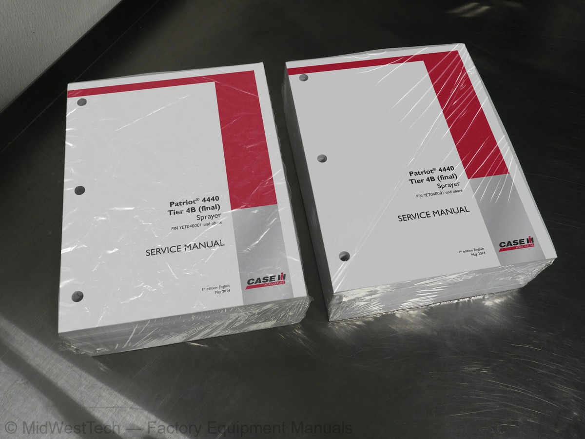
What's inside
From the manual's own table of contents: 336 topics. See sample pages (PDF, 535 KB)
- Foreword - Important notice regarding equipment servicing
- Safety rules
- Personal safety
- Safety rules - Ecology and the environment
- Torque - Minimum tightening torques for normal assembly
- Torque - Standard torque data for hydraulics
- Basic instructions - Shop and assembly
- Maintenance Chart
- Definition - Hydraulic contamination
- Capacities
- General specification
- Product identification
- Product identification - Machine orientation
- Torque
- Remove
- Install
- Remove - Air filter housing/SCR muffler sub assembly
- Install - Air filter housing/SCR muffler sub assembly
- Service instruction - Engine oil and filter change
- Cleaning - Tank inlet screen
- Remove - Muffler
- Install - Muffler
- Remove - Diesel Oxidation Catalyst (DOC)
- Install - Diesel Oxidation Catalyst (DOC)
Show all 336 topics
- Extension - Torque
- Special tools
- Dynamic description - Active suspension
- Extension - Remove - Axle adjust cylinder
- Extension - Install - Axle adjust cylinder
- Disassemble - All cylinders
- Assemble - All cylinders
- Remove - Axle extension
- Install - Axle extension
- Replace - Axle extension liners
- Remove - Spring
- Install - Spring
- Remove - Upper suspension arm
- Disassemble - Upper suspension arm
- Assemble - Upper suspension
- Install - Upper suspension arm
- Remove - Trailing link
- Disassemble - Trailing link
- Assemble - Trailing link
- Install - Trailing link
- Torque - Planetary gear hub
- Special tools - Planetary gear hub
- Test - Planetary gear hub test-roll, leak, brake
- Remove - Planetary gear hub
- Disassemble - Planetary gear hub
- Assemble - Planetary gear hub
- Install - Planetary gear hub
- Torque - Axle adjust cylinder
- Special tools - Suspension
- Torque - Suspension
- Remove - Axle adjust cylinder
- Install - Axle adjust cylinder
- Relief valve - Remove - Hydrostatic pump charge relief valve
- Relief valve - Install - Hydrostatic pump charge relief valve
- Pressure release valve - Remove - Hydrostatic pump pressure control pilot
- Pressure release valve - Install - Hydrostatic pump pressure control pilot
- General specification - Hydrostatic system pressures
- Torque - Hydrostatic pump drive
- Overview - Drive circuit
- Overview - Drive circuit troubleshooting chart
- Remove - Hydrostatic pump drive
- Disassemble - Hydrostatic pump drive
- Assemble - Hydrostatic pump drive
- Install - Hydrostatic pump drive
- Torque - Wheel motor
- Torque - Neutral shunt valve
- Dynamic description - Series 90 heavy duty pumps
- Exploded view - Wheel motor
- Dynamic description - Wheel motor
- Dynamic description - Motor Control Valve (MCV)
- Dynamic description
- Dynamic description - Neutral shunt valve
- Dynamic description - Traction assist
- Overview - Reverse valve
- Pressure test - High pressure
- Pressure test - Charge pressure
- Remove - Hydrostatic pump
- Replace - Hydrostatic pump shaft and seal replacement
- Disassemble - Hydrostatic charge pump
- Assemble - Hydrostatic charge pump
- Install - Hydrostatic pump
- Start up - Replacement start up procedure
- Remove - Wheel motor
- Service instruction - Wheel motor minor repair
- Disassemble - Wheel motor
- Component identification - Quick disconnect
- Overview
- Service instruction - Park brake release procedure
- Test - Park brake fails to release
- Disassemble
- Assemble
- Service instruction - Brake bleeding procedure
- General specification - Hydraulic system pressures
- Component localisation - Hydraulic component locations
- Overview - Cylinder system troubleshooting chart
- Hydraulic symbol - Schematic color legend
- Hydraulic schematic frame 01
- Hydraulic schematic frame 02
- Hydraulic symbol - Schematic components
- Hydraulic symbol - Pressure control
- Hydraulic symbol - Directional control
- Hydraulic symbol - Composite
- Hydraulic symbol - Flow control
- Hydraulic symbol - Table of symbols
- Remove - Hydraulic tank
- Install - Hydraulic tank
- Replace - Charge filter
- Replace
- Overview - Gear pump
- Remove - Gear pump
- Install - Gear pump
- Test - Gear pump
- Remove - Active suspension, shock absorber
- Install - Active suspension, shock absorber
- Torque - Boom height cylinder
- Torque - Manifold
- Torque - Two section valve bank
- Overview - Boom cylinders
- Overview - Two section valve bank
- Identification - Two section valve bank axle/boom height electrical
- External view - Six section and eight section valve bank
- Remove - Inner boom
- Install - Inner boom fold
- Remove - Outer and mid boom (120 foot)
- Install - Outer and mid boom (120 foot)
- Remove - Mast
- Install - Mast
- Remove - Boom pivot
- Install - Boom pivot
- Remove - Assembled center section and mast
- Install - Assembled center section and mast
- Remove - Mid boom, 120 foot
- Install - Mid boom, 120 foot
- Remove - Center section, all
- Install - Center section, all
- Remove - 120 foot boom
- Install - 120 foot boom
- Remove - Turn signal lever assembly
- Install - Forward-Neutral-Reverse-Park lever
- Replace - Tilt steering column release cable
- Adjust
- Test - Check for leaking seals
- General specification - Temperature/pressure chart
- Capacity - R134A refrigerant charge
- Service limits
- Dynamic description - Air conditioning thermal operation
- Dynamic description - Automatic Temperature Control (ATC)
- Component identification - Auto Temperature Control (ATC)
- Dynamic description - System flushing
- Dynamic description - Recovery of R134a
- Dynamic description - Leak detection
- Dynamic description - Ultra Violet (UV) dye injection
- Static description
- Test - Refrigerant
- Recover - Refrigerant
- Evacuate - Air conditioning system
- Charging - Air conditioning system
- Decontaminating - Complete circuit flushing
- Decontaminating - Component flushing
- Decontaminating - Post flushing procedures
- Pressure test
- Remove - Cab pressurizer blower
- Install - Cab pressurizer blower
- Testing - Blower power and ground
- Electrical schema - Electrical schematic circuit color index
- Electrical schematic sheet 01 - Power and starting (engine schematics)
- schematics)
- Electrical schematic sheet 03 - After treatment system (Non CAN) (engine schematics)
- Electrical schematic sheet 04 - Engine - Controller Area Network (CAN) (engine schematics)
- Electrical schematic sheet 05 - Engine inputs/outputs (engine schematics)
- Electrical schematic sheet 06 - Fuel injection (engine schematics)
- Electrical schematic sheet 03 - Circuit diagram legends and ground locations
- Electrical schematic sheet 04 - Harness codes
- Electrical schematic sheet 05 – Batteries - distribution
- Electrical schematic sheet 06 – Cab power and fuses 1 - 7
- Electrical schematic sheet 07 – Fuses 8 - 14
- Electrical schematic sheet 08 – Fuses 15 - 21
- Electrical schematic sheet 09 – Fuses 22 - 28
- Electrical schematic sheet 10 – Fuses 29 - 35
- Electrical schematic sheet 11 – Fuses 36 - 42
- Electrical schematic sheet 12 – Fuses 43 - 49
- Electrical schematic sheet 13 – Fuses 50 - 56 and keyed power
- Electrical schematic sheet 14 – Clean ground and cab pressure
- Electrical schematic sheet 15 – Cab harness splices
- Electrical schematic sheet 16 – Dome lights and autoguidance interfacing
- Electrical schematic sheet 17 – Beacon light and roof lights
- Electrical schematic sheet 18 – Roof lights
- Electrical schematic sheet 19 – Turn signal module and display interface
- Electrical schematic sheet 20 – Work light relay circuits
- Electrical schematic sheet 21 – Trans lockout and traction control
- Electrical schematic sheet 22 – Mirrors and wiper circuit
- Electrical schematic sheet 23 – HVAC modules
- Electrical schematic sheet 24 – Radio and seat control
- Electrical schematic sheet 25 – Acc ports and controller interface
- Electrical schematic sheet 26 – ICU2 interface
- Disconnect
- Connect
- Visual inspection
- Test
- Remove - Upstream Diesel Oxidation Catalyst (DOC)
- Install - Upstream Diesel Oxidation Catalyst (DOC)
- Remove - Upstream SCR canister
- Install - Upstream SCR canister
- Remove - Downstream SCR canister
- Install - Downstream SCR canister
- Remove - Downstream of SCR catalyst
- Install - Downstream of SCR catalyst
- Dynamic description - Hydrostatic pump electronic displacement control
- Component identification - Hydrostatic pump electronic displacement control
- Identification - Power train control module (Plus1 propel module) electrical
- Test - Hydrostatic pump electronic displacement control
- Adjust - Hydrostatic pump Electronic Displacement Control (EDC)
- Remove - Hydrostatic pump electronic displacement control
- Install - Hydrostatic pump electronic displacement control
- Calibrate
- Dynamic description - Blower speed/temperature control potentiometers
- Overview - Automatic Temperature Control (ATC) fault codes
- Dynamic description - Controller power, ground, and ATC switch
- Test - Blower speed/temperature control potentiometers
- Test - Connector J8 test points
- Test - Controller power, ground, and ATC switch
- Replace - Controller and blower speed driver
- Torque - Product pump control (PWM) valve
- Dynamic description - Pulse Width Modulation (PWM) valve driver
- Identification - Pulse Width Modulation (PWM) valve driver electrical
- Dynamic description - Boom pressure switch
- Identification - Fence row solenoid
- Pressure sensor - Dynamic description - Sparge pressure sensor
- Pressure sensor - Dynamic description - Boom pressure sensor
- Overview - Reload station troubleshooting chart
- Dynamic description - Pump station remote box
- Identification - Pump station remote box electrical
- Identification - Product pump control (PWM) valve electrical
- Test - Pulse Width Modulation (PWM) valve drive
- Remove - Reload station
- Install - Reload station
- Remove - Product pump control (PWM) valve
- Install - Product pump control (PWM) valve
- Test - Product pump control (PWM) valve cartridge
- Test - Product pump control (PWM) valve operation
- Test - Product pump control (PWM) valve relief valve
- Flow test - Product pump control (PWM) valve
- 10031-Controller memory error
- 10032-Controller memory error
- 10033-Controller memory error
- 10034-Controller memory error
- 10035-Controller memory error
- 10036-Controller memory error
- 1015-Seat switch stuck closed
- 11011-Fuel level sensor voltage out of range low
- 111-Cab temperature sensor open or shorted to power
- 112-Cab temperature sensor shorted to ground
- 115-Evaporator temperature sensor open or shorted to power
- 116-Evaporator temperature sensor shorted to ground
- 12091-Engine controller off line
- 120-Blower speed selector potentiometer open or shorted to power
- 121-Temperature selector potentiometer open or shorted to power
- 122-Temperature sensor temperature too high
- 125-High pressure switch (+) shorted to power
- 126-High pressure switch (+) input shorted to ground
- 127-High pressure switch (-) input shorted to power
- 128-High pressure switch (-) input shorted to ground
- 129-High pressure switch cycling error (2 times in 1 minute)
- 13010-Engine coolant temperature is error or not available
- 13020-Engine speed is error or not available
- 13040-Engine intake air temperature is error or not available
- 130-Low pressure switch (+) input shorted to power
- 131-Low pressure switch (+) input shorted to ground
- 132-Low pressure switch (-) input shorted to power
- 133-Low pressure switch (-) input shorted to ground
- 134-Low pressure switch open for more than 1 minute
- 19001-Battery voltage is higher than expected
- Configure AIM Command and PRO nozzle tip selection charts
- Overview - Application system troubleshooting chart
- Overview - AIM Command
- Dynamic description - AIM Command start-up and shut-down
- Overview - AIM Command troubleshooting chart
- Dynamic description - Boom strainers
- Plumbing schema - Fence row system
- Plumbing schema - Plumbing schematic symbols
- Plumbing schema - Boom product schematic
- Plumbing schema - Product plumbing
- Plumbing schema - Chemical induction
- Identification
- Overview - Chemical inductor troubleshooting chart
- Control valve - Dynamic description - Boom section shut-off valves
- Control valve - Dynamic description - Product throttling valve
- Dynamic description - Check valve
- Identification - Sparge valve electrical
- Component identification - Pump on sensor electrical
- Identification - Boom pressure sensor electrical
- Identification - Boom kPa (PSI) switch electrical
- Dynamic description - Product flowmeter
- Identification - Product flowmeter electrical
- Disassemble - Product pump motor
- Assemble - Product pump motor
- Test - Product pump motor
- Bleed Bleeding pressure from product plumbing
- Remove - Product flowmeter
- Overhaul - RFM 60P Flowmeter
- Overhaul - RFM 100 Flowmeter
- Replace - RFM 60P and RFM 100 Flowmeter sensor
- Install - Product flowmeter
- Calibrate - Product flowmeter
- Test - Product flowmeter wire testing
- Identification - Foam marker electrical
- Plumbing schema - Rinse tank and foamer system
- Dynamic description - Control module
- Dynamic description - Control potentiometer
- Dynamic description - Auto advance feature
- Dynamic description - Valve/strainer
- Dynamic description - Liquid pump motor
- Dynamic description - Liquid solenoid
- Dynamic description - Foam concentrate transfer system
- Overview - Foam marker system troubleshooting chart
- Overview - Foam concentrate transfer system troubleshooting chart
- Plumbing schema - Air tank
- Dynamic description - Air tank
- Dynamic description - Air regulator
- Dynamic description - Air solenoid(s)
- Remove - Mixing chamber
- Install - Mixing chamber
- Remove - Air tank
- Install - Air tank
- Remove - Engine shroud
- Install - Engine shroud
- Remove - Front hood
- Install - Front hood
- Torque - Operator ladder cylinder
- Remove - Operator ladder cylinder
- Install - Operator ladder cylinder
- Tilt - Accessing the HVAC box
Inside this manual
Real pages from this service manual (2,569 pages). Open the sample pages (PDF, 534 KB)

- Specifications, page 105: INTRODUCTION
- Diagram, page 924: Electrical systems - Harnesses and connectors
- Troubleshooting, page 1,665: 129-High pressure switch cycling error (2 times in 1 minute)
- Color page: Spraying - Chemical spraying
- Foldout diagram (color): Electrical systems - Harnesses and connectors
Other manuals for this machine
Save 10% on 2 manuals, 15% on 3 or more. Other manuals for the Patriot 4440 Tier 4B are listed below. Editions cover different serial number ranges: check the serial coverage and tick only the ones that match your machine.
Added to your cart. View cart
This is a service manual
Here's how it compares to the other manual types.
Service manual
Factory repair procedures and technical information such as specifications, troubleshooting, and wiring and hydraulic diagrams, for the models and systems the manual covers. See What's inside for its topics.
Operator's manual
Safe operation, controls, maintenance schedules, lubrication points, inspections, and basic checks. Repair procedures are in the service manual.
Parts manual
Illustrated diagrams with factory part numbers for identifying components and ordering parts. Repair procedures are in the service manual.
Engine service manuals are sometimes sold separately, since certain machine models were offered with more than one engine option.
What it's used for
Factory manual for in-house farm and construction shop use. Straightforward, complete, and easy to follow. It contains the OEM information dealership service departments and parts counters use to diagnose problems, identify components, and perform maintenance or repairs correctly.
Service shops and owner/operators who repair their own equipment
Identifying correct parts and seeing how assemblies come apart and go back together
Keeping equipment running with less downtime
Factory manual, 2,569 pages
Quantity one is the manual described above.
Fast free USA shipping
Ships in 1 business day.
60-day returns
Free if the mistake is ours. A manual ordered in error must come back unopened in its shrink-wrap; you pay return shipping and a 20% restocking fee applies. Return policy
Binder not included
Manuals over about 300 pages may need a standard 3-ring binder, which you can buy locally to keep the pages organized for shop use.
Questions about model, serial number, engine coverage or contents? Contact us before purchasing and we'll help confirm it's the right manual. Please verify the manual type, machine model, serial number range and engine coverage before purchasing: manuals ordered in error carry a 20% restocking fee (return policy).