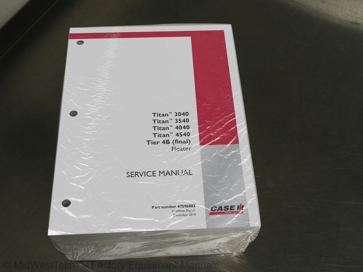
Case Titan 3040, 3540, 4040, 4540 Tier 4B Floater Service Manual
2,261 pages · Publication 47596802
Added to your cart. View cart
- Models
- Titan 3040, 3540, 4040, 4540 Tier 4B
- Manual type
- Service Manual
- Pages
- 2,261
- Publication
- 47596802
- Condition
- Brand new
What's inside
From the manual's own table of contents: 187 topics. See sample pages (PDF, 642 KB)
- Foreword - Important notice regarding equipment servicing
- Safety rules
- Safety rules - Ecology and the environment
- Torque - Minimum tightening torques for normal assembly
- Torque - Standard torque data for hydraulics
- Basic instructions - Shop and assembly
- Maintenance chart - Three wheel units (*)
- Maintenance chart - Four wheel units (*)
- Hydraulic contamination
- Capacities - Three wheel units (*)
- Capacities - Four wheel units (*)
- General specification - Three wheel units (*)
- General specification - Four wheel units (*)
- Product identification - Three wheel units (*)
- Product identification - Four wheel units (*)
- Product identification - Three wheel machine orientation (*)
- Product identification - Four wheel machine orientation (*)
- Torque
- Special tools
- Remove - Four wheel units (*)
- Install - Four wheel units (*)
- Remove - Three wheel units (*)
- Install - Three wheel units (*)
- Remove - Three wheel unit, air to air/A/C condensor (*)
Show all 187 topics
- Disassemble - Three wheel unit, air to air/A/C condensor (*)
- Install - Three wheel unit, air to air/A/C condensor (*)
- Remove - Four wheel unit, cooling system assembly (*)
- Disassemble - Four wheel unit, cooling system assembly (*)
- Assemble - Four wheel unit, cooling system assembly (*)
- Install - Four wheel unit, cooling system assembly (*)
- Remove
- Disassemble
- Assemble
- Install
- Torque - Three wheel units (*)
- Special tools - Three wheel units (*)
- Torque - Four wheel units (*)
- Replace - Three wheel units, bearing replacement (*)
- Disassemble - Three wheel units (*)
- Assemble - Three wheel units (*)
- Remove - Four wheel units, wheel hub (*)
- Inspect - Four wheel units, wheel hub (*)
- Install - Four wheel units, wheel hub (*)
- Alignment - Four wheel units, wheel alignment (*)
- End play - Four wheel units, steering knuckle vertical end play (*)
- Check - Four wheel units, upper and lower king pin bushings (*)
- Check - Four wheel units, tie rod ends (*)
- End play - Four wheel units, front wheel bearings (*)
- Angle adjust - Four wheel units, maximum turn angle (*)
- Toe in adjust - Four wheel units (*)
- Inspect - Four wheel units (*)
- Shimming - Setting backlash
- Torque - Three wheel units, front brakes (*)
- Torque - Rear axle brakes
- Dynamic description - Braking system
- Replace - Three wheel units, front pad (*)
- Remove - Three wheel units, front rotor (*)
- Install - Three wheel units, front rotor (*)
- Remove - Three wheel units, front caliper (*)
- Install - Three wheel units, front caliper (*)
- Replace - Four wheel units, front brake shoes (*)
- Disassemble - Rear axle brakes
- Replace - Rear axle brake shoes
- Assemble - Rear axle brakes
- Hydraulic schema - Three wheel units (*)
- Hydraulic schema - Four wheel units (*)
- Component localization - Three wheel units (*)
- Component localization - Four wheel units (*)
- Dynamic description
- Replace - Three wheel units, fluid and filter (*)
- Replace - Four wheel units, fluid and filter (*)
- Torque - Gear pump
- Remove - Three wheel units, gear pump (*)
- Install - Three wheel units, gear pump (*)
- Remove - Four wheel units, gear pump (*)
- Install - Four wheel units, gear pump (*)
- Raise - Three wheel units, front (*)
- Raise - Four wheel units, front (*)
- Raise - Three wheel units, rear (*)
- Raise - Four wheel units, rear (*)
- Torque - Three wheel units, front steering fork (*)
- Special tools - Three wheel units, front steering fork (*)
- Remove - Three wheel units, front steering fork (*)
- Install - Three wheel units, front steering fork (*)
- Remove - Turn signal lever assembly
- Install - Turn signal lever assembly
- Replace - Tilt steering column release cable
- Component identification
- Overview - Orbit motor
- General specification - Temperature/pressure chart
- Capacity - R134A refrigerant charge
- Service limits
- Dynamic description - Air conditioning thermal operation
- Dynamic description - Automatic Temperature Control (ATC)
- Component identification - Auto Temperature Control (ATC)
- Dynamic description - System flushing
- Dynamic description - Recovery of R134a
- Dynamic description - Leak detection
- Dynamic description - Ultra Violet (UV) dye injection
- Static description
- Test - Refrigerant
- Recover - Refrigerant
- Evacuate - Air conditioning system
- Charging - Air conditioning system
- Decontaminating - Complete circuit flushing
- Decontaminating - Component flushing
- Decontaminating - Post flushing procedures
- Pressure test
- Remove - Cab pressurizer blower
- Install - Cab pressurizer blower
- Testing - Blower power and ground
- Electrical schema - Electrical schematic circuit color index
- Electrical schematic sheet 01 - Power and starting (engine schematics)
- schematics)
- Electrical schematic sheet 03 - After treatment system (Non CAN) (engine schematics)
- Electrical schematic sheet 05 - Engine inputs/outputs (engine schematics)
- Electrical schematic sheet 06 - Fuel injection (engine schematics)
- Electrical schematic sheet 04 - Ground locations
- Electrical schematic sheet 06 - Batteries/distribution
- Electrical schematic sheet 07 - Cab power and fuses 001 - 014
- Electrical schematic sheet 08 - Fuses 015 - 028
- Electrical schematic sheet 09 - Fuses 029 - 042
- Electrical schematic sheet 10 - Fuses 043 - 056
- Electrical schematic sheet 11 - Clean ground, cab pressure and keyed power
- Electrical schematic sheet 12 - Cab harness splices
- Electrical schematic sheet 13 - Dome lights and autoguidance interfacing
- Electrical schematic sheet 14 - Beacon light and roof lights
- Electrical schematic sheet 15 - Roof lights
- Electrical schematic sheet 16 - Turn signal module and display interface
- Electrical schematic sheet 17 - Work light relay circuits
- Electrical schematic sheet 18 - Transmission lockout and traction control
- Electrical schematic sheet 19 - Mirror and wiper circuits
- Electrical schematic sheet 20 - HVAC modules
- Electrical schematic sheet 21 - Radio and seat circuits
- Electrical schematic sheet 22 - Accessory ports and controller interface
- Electrical schematic sheet 23 - ICU2 interface
- Electrical schematic sheet 24 - Brake, PB, Neutral, horn and backup relays
- Electrical schematic sheet 25 - Front dash
- Electrical schematic sheet 26 - Head and work light controls
- Electrical schematic sheet 27 - Vehicle CAN buss
- Electrical schematic sheet 28 - Application and Ag CAN busses
- Electrical schematic sheet 29 - TPS and cruise splices
- Remove - DOC upstream, four wheel units (*)
- Install - DOC upstream, four wheel units (*)
- Remove - SCR upstream, four wheel units (*)
- Install - SCR upstream, four wheel units (*)
- Remove - SCR downstream, four wheel units (*)
- Install - SCR downstream, four wheel units (*)
- Remove - DOC upstream, three wheel units (*)
- Install - DOC upstream, three wheel units (*)
- Remove - SCR upstream, three wheel units (*)
- Install - SCR upstream, three wheel units (*)
- Remove - SCR downstream, three wheel units (*)
- Install - SCR downstream, three wheel units (*)
- Remove - Upstream, four wheel units (*)
- Install - Upstream, four wheel units (*)
- 10031-Controller memory error
- 10032-Controller memory error
- 10033-Controller memory error
- 10034-Controller memory error
- 10035-Controller memory error
- 10036-Controller memory error
- 1015-Seat switch stuck closed
- 11011-Fuel level sensor voltage out of range low
- 111-Cab temperature sensor open or shorted to power
- 112-Cab temperature sensor shorted to ground
- 115-Evaporator temperature sensor open or shorted to power
- 116-Evaporator temperature sensor shorted to ground
- 12091-Engine controller off line
- 120-Blower speed selector potentiometer open or shorted to power
- 121-Temperature selector potentiometer open or shorted to power
- 122-Temperature sensor temperature too high
- 125-High pressure switch (+) shorted to power
- 126-High pressure switch (+) input shorted to ground
- 127-High pressure switch (-) input shorted to power
- 128-High pressure switch (-) input shorted to ground
- 129-High pressure switch cycling error (2 times in 1 minute)
- 13010-Engine coolant temperature is error or not available
- 13020-Engine speed is error or not available
- 13040-Engine intake air temperature is error or not available
- 130-Low pressure switch (+) input shorted to power
- 131-Low pressure switch (+) input shorted to ground
- 132-Low pressure switch (-) input shorted to power
- 133-Low pressure switch (-) input shorted to ground
- 134-Low pressure switch open for more than 1 minute
- 19001-Battery voltage is higher than expected
- Tilt - Accessing the HVAC box
Inside this manual
Real pages from this service manual (2,261 pages). Open the sample pages (PDF, 641 KB)

- Specifications, page 233: Transmission - Hi-Lo unit
- Diagram, page 1,108: CONNECTOR X-9002 - Engine Control Unit (ECU)
- Troubleshooting, page 1,528: 130-Low pressure switch (+) input shorted to power
- Color page: Electrical systems - Harnesses and connectors
- Color page: Electrical systems - Harnesses and connectors
- Foldout diagram (color): Electrical systems - Harnesses and connectors
Other manuals for this machine
Save 10% on 2 manuals, 15% on 3 or more. Other manuals for the 4540 Tier 4B are listed below. Editions cover different serial number ranges: check the serial coverage and tick only the ones that match your machine.
Added to your cart. View cart
This is a service manual
Here's how it compares to the other manual types.
Service manual
Factory repair procedures and technical information such as specifications, troubleshooting, and wiring and hydraulic diagrams, for the models and systems the manual covers. See What's inside for its topics.
Operator's manual
Safe operation, controls, maintenance schedules, lubrication points, inspections, and basic checks. Repair procedures are in the service manual.
Parts manual
Illustrated diagrams with factory part numbers for identifying components and ordering parts. Repair procedures are in the service manual.
Engine service manuals are sometimes sold separately, since certain machine models were offered with more than one engine option.
What it's used for
Factory manual for in-house farm and construction shop use. Straightforward, complete, and easy to follow. It contains the OEM information dealership service departments and parts counters use to diagnose problems, identify components, and perform maintenance or repairs correctly.
Service shops and owner/operators who repair their own equipment
Identifying correct parts and seeing how assemblies come apart and go back together
Keeping equipment running with less downtime
Factory manual, 2,261 pages
Quantity one is the manual described above.
Fast free USA shipping
Ships in 1 business day.
60-day returns
Free if the mistake is ours. A manual ordered in error must come back unopened in its shrink-wrap; you pay return shipping and a 20% restocking fee applies. Return policy
Binder not included
Manuals over about 300 pages may need a standard 3-ring binder, which you can buy locally to keep the pages organized for shop use.
Questions about model, serial number, engine coverage or contents? Contact us before purchasing and we'll help confirm it's the right manual. Please verify the manual type, machine model, serial number range and engine coverage before purchasing: manuals ordered in error carry a 20% restocking fee (return policy).