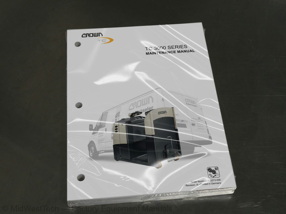
Crown TC 3000 Tow Tractor Service Manual
216 pages · Publication 812573-006
Added to your cart. View cart
- Models
- TC 3000
- Manual type
- Service Manual
- Pages
- 216
- Publication
- 812573-006
- Condition
- Brand new
What's inside
From the manual's own table of contents: 220 topics. See sample pages (PDF, 661 KB)
- Description of Symbols and Indicators
- Safety Notices
- Other indicators
- General Safety Instructions
- Maintenance and Repair Instructions
- Maintenance and Repairs
- Before Parking the Truck
- Before Working on the Truck
- Before Starting the Truck
- Warning and Instruction Decals on the Truck
- General
- Service Training
- Replacement Parts
- Additional Attachments and Modifications
- Using the Manual
- Contact Address
- Models
- Lifting and Jacking up the Truck
- Lifting the Truck
- Lifting the truck with a crane
- Lifting the truck with a forklift truck
- Jacking up the Truck
- Towing the Truck
- Taking the Truck out of Service
Show all 220 topics
- Testing Re-Commissioned Trucks
- Restoring the Truck to Service
- Recommended Lubricants and Accessories
- Cold Store Trucks
- Planned Maintenance
- Inspection and Lubrication Points
- Torques
- Standard Torques
- Castor Wheels and Skids
- Adjusting the Castor Wheels and Skids
- Changing the Transmission Oil
- Components
- Replacing the Output Shaft Seal
- Special Tools Required
- Preparation
- Shaft Seal Removal
- Output shaft removal
- Output shaft assembly
- Drive Wheel and Wheel Bolt Replacement
- Drive Wheel Disassembly
- Replacing the Wheel Bolts
- Drive Wheel Assembly
- Replacing the Drive Unit
- Drive Unit Removal
- Drive Unit Installation
- Repairing the Drive Transmission Unit
- Drive Transmission Unit Disassembly
- Bevel gear and bevel pinion removal
- Drive Transmission Unit Assembly
- Bevel pinion and drive pinion assembly
- Bevel gear assembly
- Wire Colour Code
- Contact Symbol Abbreviations
- Electrical Wiring Diagrams
- Operator Menu
- Service Menu
- Analyzer Menu - Status & Inputs
- Analyzer Menu - Outputs
- Analyzer Menu - Access 2 Inputs
- Analyzer Menu - Access 3 Inputs
- Analyzer Menu - Access 5 Inputs
- Analyzer Menu - Test Outputs
- Calibration - Rocker & Load Sensor
- Calibration - Steer System
- Features
- Hours
- Events
- Performance
- Utilities
- Parameter Setting
- Calibration
- Selecting the CALIBRATION Menu
- Calibrating the Traction Potentiometer
- Steering Calibration
- Control Modules
- Power Fuses
- Servicing and Replacing the Control Modules
- Discharging the Capacitors
- Servicing the Control Modules
- Replacing Control Modules
- Removal
- Assembly
- Event Codes - Access 3
- Event Codes - Access 5
- Drive Motor
- Drive Motor Disassembly
- Drive Motor Assembly
- Repairing the Drive Motor
- Dismantling the Rotor Assembly
- Assembling the Rotor Assembly
- Final task
- Steer Motor
- Steer Motor Disassembly
- Steer Motor Assembly
- Repairing the Steer Motor
- Final tasks
- Battery
- Charging the Battery
- Replacing the Battery
- Contactors - Inspection and Repairs
- Inspection
- Contacts
- Coils
- Springs
- Servicing
- Dismantling
- Control Module Safety Test
- Required tools
- Carrying out the PMT
- Testing Access 3 (TCM)
- Testing Access 5 (SCM)
- Electromechanical Brake
- Servicing the Brake
- Measuring the air gap
- Repairing the Brake
- Installing a wear part kit
- Replacing the brake in full
- Steering Assembly Installation and Removal
- Steering Assembly Components
- Steering Assembly Removal
- Steering Assembly Installation
- Final Tasks
- Steering Transmission Repair
- Steering Transmission Disassembly
- Steering Transmission Assembly
- Tiller Handle Components
- Tiller Handle Shell Removal and Assembly
- Tools Required
- Shell Removal
- Shell Assembly
- Switch Unit Removal / Assembly
- Switch Unit Disassembly
- Switch Unit Assembly
- Rabbit/Turtle” Toggle Module Disassembly
- Rabbit/Turtle” Toggle Module Assembly
- Replacing the Tiller Handle PC Boards
- Hydraulic PC Board Removal
- Hydraulic PC Board Assembly
- Main PC Board Disassembly
- Main PC Board Assembly
- (POT Travel Switch)
- Traction Potentiometer Removal
- Traction Potentiometer Assembly
- Traction Potentiometer Calibration
- Safety Reverse Switch Removal and Assembly
- Safety Reverse Switch Removal
- Safety Reverse Switch Assembly
- Grip and Horn Switch Removal and Assembly
- Control Handle Overview
- Tiller Removal / Assembly
- Tiller Removal
- Tiller Assembly
- Tiller Recuperating Spring Removal / Assembly
- Recuperating Spring Removal
- Recuperating Spring Assembly
- Steer Sensor Removal / Assembly
- Steer Sensor Removal
- Steer Sensor Assembly
- Testing the Steer Sensor via the Analyzer Menu
- Platform Overview
- Replacing the Platform Sensors
- Platform Sensor Removal
- Platform Sensor Assembly
- Platform Assembly and Testing the Platform Sensors
- Testing the Platform Sensors via the Analyzer Menu
- Possible error cause
- Overview
- With Key Switch and Keypad
- Access™ 3/2 - Drive Side
- Access 2/3 - Logic Side
- Access 5 - Logic Side
- Access 8.1 - Tiller
- Access 8.2 - Backrest
- Switch Connection
- Tiller Circuits
- Access 1 with Options
- CAN connection
- Abbreviation List
- Connectors and Sockets
- Switches and Sensors
- Wires and Wire Harnesses
- Fuses and Fuse Holders
- Drives
- Power Cables
- Wire Harness - Hitch Position Control Switch
- Assembly - Hitch Position Control Switch
- Wire Harness - Hitch Position Control Switch F/C
- Horn Wire Harness
- Horn Switch Assembly
- Assembly - SAS Switch
- Main Harness
- Spline Overview
- X10 Handle Wire Harness
- Display Wire Harness
- Programmer Connector
- CAN Handle Connection Wire Harness
- Straight Ahead Sensor
- Battery lock switch (BLS)
- Key Switch Adapter
- DC / DC Converter Connector Cable
- DC / DC Converter
- Power Supply Cables
- Strobe Wire Harness
- Keypad Adapter
- CAN Bus and Fuse Cable Extension
- CAN Bus cable extension
- Fuse Cable Extension
- Main Contactor Cable Extension
- Heating Assembly
- Alarm Connection Cable
- Horn Filter Wire Harness
- Cable Pin 1 Filter
- Cable Pin 3 Filter
- Cable Pin 5 Filter
- Beacon Filter
- Fan Wire Harness
Inside this manual
Real pages from this service manual (216 pages). Open the sample pages (PDF, 659 KB)
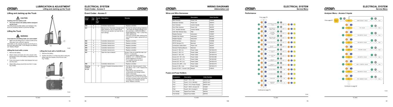
- Specifications, page 23: LUBRICATION & ADJUSTMENT
- Troubleshooting, page 104: Event Codes - Access 5
- Diagram, page 179: WIRING DIAGRAMS
- Color page, page 89: ELECTRICAL SYSTEM
- Color page, page 71: ELECTRICAL SYSTEM
This is a service manual
Here's how it compares to the other manual types.
Service manual
Factory repair procedures and technical information such as specifications, troubleshooting, and wiring and hydraulic diagrams, for the models and systems the manual covers. See What's inside for its topics.
Operator's manual
Safe operation, controls, maintenance schedules, lubrication points, inspections, and basic checks. Repair procedures are in the service manual.
Parts manual
Illustrated diagrams with factory part numbers for identifying components and ordering parts. Repair procedures are in the service manual.
Engine service manuals are sometimes sold separately, since certain machine models were offered with more than one engine option.
What it's used for
Factory manual for in-house farm and construction shop use. Straightforward, complete, and easy to follow. It contains the OEM information dealership service departments and parts counters use to diagnose problems, identify components, and perform maintenance or repairs correctly.
Service shops and owner/operators who repair their own equipment
Identifying correct parts and seeing how assemblies come apart and go back together
Keeping equipment running with less downtime
Factory manual, 216 pages
Quantity one is the manual described above.
Fast free USA shipping
Ships in 1 business day.
60-day returns
Free if the mistake is ours. A manual ordered in error must come back unopened in its shrink-wrap; you pay return shipping and a 20% restocking fee applies. Return policy
Other editions and similar models
Questions about model, serial number, engine coverage or contents? Contact us before purchasing and we'll help confirm it's the right manual. Please verify the manual type, machine model, serial number range and engine coverage before purchasing: manuals ordered in error carry a 20% restocking fee (return policy).