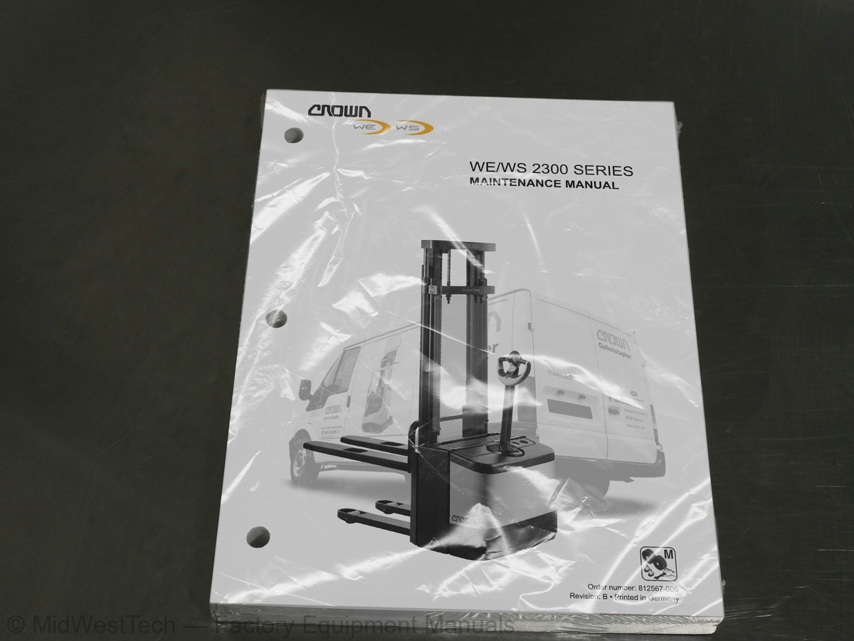
Crown WE, WS 2300 Walkie Stacker Service Manual
432 pages · Publication 812567-006
Added to your cart. View cart
- Models
- WE, WS 2300
- Manual type
- Service Manual
- Pages
- 432
- Publication
- 812567-006
- Condition
- Brand new
What's inside
From the manual's own table of contents: 391 topics. See sample pages (PDF, 557 KB)
- Symbols Used
- Safety Symbols
- General Symbols
- Fork direction
- General Safety Instructions
- Maintenance and Repair Instructions
- Maintenance and Repairs
- Before Parking the Truck
- Before Working on the Truck
- Before Starting the Truck
- Warning and Instruction Decals on the Truck
- General
- Operator Manual
- Service Training
- Ordering Spare Parts
- Using the Manual
- Models
- Component Access
- Drive Unit Cover
- Control Handle
- Control Handle Knuckle
- Mast
- Platform and Side Restraints(2)
- Lifting the Truck
Show all 391 topics
- Lifting with a Crane
- Lifting with a Forklift Truck
- Towing the Truck
- Jacking up the Truck
- Service
- Recommended Lubricants
- Cold Store Trucks
- Taking the Truck out of Service
- Returning the Truck to Service
- Recommended Lubricants and Consumables
- Inspection and Maintenance Schedule
- Daily or Every 8 Service Hours
- Safety Reverse Switch Test
- Test and Maintenance Interval Chart
- Load Wheels and Castors
- Single Load Wheel Replacement (WE)
- Removal
- Assembly
- Tandem Load Wheel Replacement (WE)
- Tandem Load Wheel Replacement (WS)
- Castor (WE/WS)
- Castor (WE-S/WS-S)
- Castor Suspension (WE/WS)
- Castor Suspension (WE-S/WS-S)
- Torques
- Standard Torques
- Hydraulic Schematic Symbols
- General Principles
- Hydraulic Lines and Ports
- Bleeding the Hydraulic System
- Drift Test
- Lifting
- Pump Unit
- Reservoir
- Bleeding the Manifold
- Replacing the Filter
- Valve Block
- Relief Valve
- Relief Valve Setting
- Relief Valve Test and Setting
- Hydraulic Pump
- Hydraulic System Troubleshooting
- Drive Wheel
- Drive Unit Removal and Assembly
- Gear Unit
- Repairing the Gear Unit
- Preparation
- Dismantling
- Adjusting the bevel gear set
- Oil Change
- Draining Oil
- Adding Oil
- Live Ring Bearing
- Pivoting Carriage
- Adjusting the pivoting carriage
- Wire colour code
- Contact Symbol Abbreviations
- Electrical wiring diagrams
- Electrical Components
- Switch
- (ALM) Travel alarm
- (BBD) Battery connector
- (BDI) Unigage
- (BRK) Brake
- (BRS) Brake switch
- (Charger) On-board charger
- (EDS) Emergency Power Disconnect Switch
- (F/R Contactor) Direction contactor
- (DR) Travel alarm driver
- (FU) Fuses
- (GCSR) Gate closed switch right
- (GCSL) Gate closed switch left
- (HCM) Hydraulic control module
- (HM) Horn
- (HNS) Horn switch
- (HSS) “Rabbit/Turtle” toggle switch
- (HYD PCB) Hydraulic printed circuit board
- (KYS) Key switch
- (LMS) Limit switch
- (LMS2) Limit switch
- (MAIN PCB) Main circuit board
- (M2) Pump motor
- (ORS) Override switch
- (P) Pump contactor
- (PC) Plug holder
- (PCB) Distributor PCB
- (PLM) Platform logic
- (PLS) Platform switch
- (PM / M2) Hydraulic motor
- (POT, FS, RS) Traction pod
- (PV) Proportional valve
- (RAS, LOS1, LOS2) Raise / lower switches
- Safety reverse switch (SAS)
- (SLS / SRS) Aux. hydraulics switch
- SVH Toggle valve
- (SVA1 / SVA2) Aux. hydraulics valves
- (THS) Motor thermal switch
- (TM / M1) Traction motor
- Component Assembly Locations
- Traction Controller 1207
- Functions
- Key switch
- Current limit
- Overvoltage protection
- Overtemperature protection
- Performance reduction for low voltage
- Fault identification
- Error log
- Control Panel
- Adjusting potentiometer
- Programmer connection
- Status LED
- Diagnostics with the status LED
- Traction Controller Error Messages
- Error Reset
- Test Procedure
- Pulse Monitor Trip Test (PMT)
- Equipment
- Test
- PMT Test Wiring Diagram
- Programmer
- Connection
- Operation
- Key Functions
- Key Combinations
- SPECIAL DIAGNOSTIC menu
- SPECIAL PROGRAM menu
- Programmer
- Menus
- Main menu
- Hand Held Unit Settings
- Traction Controller Settings
- Traction Controller Type 1207-1115 Setting
- Traction Controller Type 1207-1144 Setting
- WE 1.4t Platform / WS 1.4t Platform
- Programmer Menus
- Program" Menu
- Test” Menu
- Diagnostics” and “Special Diagnostics” Menus
- Special Program” Menu
- BDI / TT
- Battery Discharge Indicator / Hourmeter
- Servicing
- Battery Discharge Indicator (BDI)
- Battery Discharge Indicator Setting (BDI)
- Calibration
- Functional Description
- Platform Logic Controller, Part No. 815043
- KYS Key Switch
- Speed Limit Switch (LMS)
- Speed Limit Switch on Mast (LMS2)
- Brake Switch (BRS)
- Override Switch (ORS)
- Emergency Disconnect Switch (EDS)
- On Board Charger
- Battery Charging Phases
- First Phase (I1)
- Second Phase (P)
- Third Phase (U)
- Fourth Phase (I2)
- End of Normal Charging
- Special Charging Phases
- Compensating Charge
- Float Charge
- Partial Charging
- Charging Errors
- Green LED is not lit
- Green LED flashing
- Important Technical Data
- Replacing the Charger
- Removal / Assembly
- Green LED not lit
- Motors
- General Maintenance Instructions
- Important Maintenance Instructions
- Traction Motor
- Repairs
- Pump Motor
- Maintenance
- Accessing brushes
- Bearings
- Electrical Panel
- Contactors
- Inspection
- Contacts
- Coils
- Springs
- Checking the coils
- Travel contactor, part no. 802815
- Travel contactor, part no. 804226
- Contactor Removal / Assembly
- Travel Contactor
- Lift Contactor
- Battery
- Removal & Installation
- Removal with a lifting device
- Removal using the optional battery rollers
- Servicing the Battery
- Battery Connector
- Hydraulic Control Module (HCM)
- Brake Operation
- Repairing the Brake
- Brake Air Gap Adjustment
- Setting the Braking Distance
- Default setting
- Testing and Adjusting the Braking Distance
- Calculating the braking distance
- Control Handle Return Springs
- Spring Tension Adjustment
- Spring Removal
- Cardan Joint
- Steering Chain
- Tensioning the steering chain
- Forward Travel
- Test and Adjustment
- Tiller Handle Components
- Main Components
- Tools required
- Hand Grip Shells
- Switch Unit
- Rabbit/Turtle” Toggle Switch
- Hydraulic PC Board
- Main PC Board
- Potentiometer
- Safety Reverse Switch
- Horn Switch
- Hand grip
- Auxiliary Hydraulics Switch
- Lifting Gear Minimum Capacity
- Fork Carriage
- Adjusting the fork carriage clearance
- Mast Maintenance
- Greasing the Roller Tracks
- Mast rollers
- Lift Chains
- Cleaning Methods
- Wear
- Freedom of Movement of Chain Links
- Chain Tension
- Chain Anchor and Pulleys
- Worn Connection Plates
- Protruding or Turned Chain Pins
- Corrosion
- Chain Lateral Wear
- Uneven Chain Tension
- Misaligned Lift Components
- Lift Chain Lubrication
- Separating Lift Chains
- Tools and Equipment Required
- Separation
- Forks
- Terms
- Fork identification
- Checking the Forks
- Crack Inspection
- Heel area
- Welding seams
- Verticality Test
- Fork Blade Warping
- Measuring the Fork Tip Width
- Fork Tine Height Difference
- Fork Stop
- Fork Blade Wear
- Seal Assembly
- Safety When Working on Hydraulic Systems
- Components
- Rod Seal Assembly
- Large Rod Seal Assembly
- Small Seal Rod Assembly
- Rod Seal Assembly, Sealing Lip First
- Cylinder Removal and Assembly
- TL Mast Lift Cylinder
- Seal Replacement
- Installing TL Mast Lift Cylinders
- TF Mast Lift Cylinders
- Removing the TF Mast Lift Cylinders
- Installing TF Mast Lift Cylinders
- TF Free Lift Cylinder
- Installing Carriage Cylinder
- Cylinder Bleeding and Flushing
- Bleeding - Mast Lift Cylinders
- Bleeding - Free Lift Cylinder (if applicable)
- (if applicable)
- Cylinder Shimming
- Lift Cylinder Shims
- Free Lift Cylinder Shims
- HYDRAULIC CYLINDERS
- Simplex mast cylinder
- Lift Cylinder
- Folding Platform
- Mechanical Adjustment
- Adjusting the Platform Switch (PLS)
- Platform Cushioning
- Layering the disk springs
- Side restraint
- Schematic Diagram, Standard
- Distribution Panel, Standard
- Traction Controller - Power Side, Standard
- Brake Circuit, Standard
- Control Handle Circuit, Standard
- Schematic Diagram, Options
- Distribution Panel, Options
- Traction Controller - Power Side, Options
- Brake Circuit, Options
- Instrument & Proportional Electronic Circuit, Options
- Control Handle Circuit, Options
- Schematic Diagram, Auxiliary Hydraulics
- Distribution Panel, Auxiliary Hydraulics
- Traction Controller, Auxiliary Hydraulics
- Brake Circuit, Auxiliary Hydraulics
- Instrument & Prop. Electronics & Sideshift Circuit
- Control Handle Circuit, Auxiliary Hydraulics
- Control Handle Wire Harness
- Horn Harness
- Main Harness, Standard
- Main Harness, Auxiliary Hydraulics
- Hourmeter Harness
- Harness, Brake
- Harness, Control Module
- Proportional Hydraulics Connector Lead, Standard
- ORS Jumper
- Power Cables
- Walkie / Rider Circuit, Standard
- Schematic Diagram, Option
- Distribution Panel, Option
- Traction Controller - Power Side, Option
- Brake Circuit, Option
- Walkie / Rider Circuit, Option
- Instrument & Proportional Electronic Circuit, Option
- Control Handle Circuit, Option
- Traction Controller, Power Side, Auxiliary Hydraulics
- Walkie / Rider Circuit, Auxiliary Hydraulics
- Auxiliary Hydraulics
- Control Handle Harness
- Harness 1, Platform
- Harness 2, Platform
- Walkie / Rider, Standard
- Instrument & Platform Logic, Standard
- Traction Controller, Option
- Instrument & Platform Logic, Option
- Platform Logic, Auxiliary Hydraulics
- Main Harness
- Harness, ORS - BRS - BRK
- Harness, TCM
- Harness, Platform Logic
- Platform Cable 1
- Platform Cable 2
- Cable, LMS2
- Option Connection, Thermal Switch, Standard
- Option Connection, Thermal Switch, Options
- Strobe & Alarm Signal Optional Harness
- Mast Cable for Strobe Light
- Electric Diagram, Standard
- Traction Controller, Power Side, Standard
- PLM - Platform Logic Module, Walkie /Rider Circuit
- Walkie / Rider Circuit, Options
- Hydraulic Diagrams
- WE/WS TL
- WE/WS TF
- WE/WS TT
- WS Auxiliary Hydraulics TL Mast
- WS Auxiliary Hydraulics TT Mast
- WE/WS
- TL Mast
- Abbreviations
- TT mast
- TF mast
Inside this manual
Real pages from this service manual (432 pages). Open the sample pages (PDF, 557 KB)
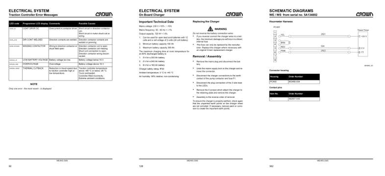
- Troubleshooting, page 110: ELECTRICAL SYSTEM
- Specifications, page 146: ELECTRICAL SYSTEM
- Diagram, page 380: WE / WS from serial no. 5A134882
This is a service manual
Here's how it compares to the other manual types.
Service manual
Factory repair procedures and technical information such as specifications, troubleshooting, and wiring and hydraulic diagrams, for the models and systems the manual covers. See What's inside for its topics.
Operator's manual
Safe operation, controls, maintenance schedules, lubrication points, inspections, and basic checks. Repair procedures are in the service manual.
Parts manual
Illustrated diagrams with factory part numbers for identifying components and ordering parts. Repair procedures are in the service manual.
Engine service manuals are sometimes sold separately, since certain machine models were offered with more than one engine option.
What it's used for
Factory manual for in-house farm and construction shop use. Straightforward, complete, and easy to follow. It contains the OEM information dealership service departments and parts counters use to diagnose problems, identify components, and perform maintenance or repairs correctly.
Service shops and owner/operators who repair their own equipment
Identifying correct parts and seeing how assemblies come apart and go back together
Keeping equipment running with less downtime
Factory manual, 432 pages
Quantity one is the manual described above.
Fast free USA shipping
Ships in 1 business day.
60-day returns
Free if the mistake is ours. A manual ordered in error must come back unopened in its shrink-wrap; you pay return shipping and a 20% restocking fee applies. Return policy
Binder not included
Manuals over about 300 pages may need a standard 3-ring binder, which you can buy locally to keep the pages organized for shop use.
Other editions and similar models
Questions about model, serial number, engine coverage or contents? Contact us before purchasing and we'll help confirm it's the right manual. Please verify the manual type, machine model, serial number range and engine coverage before purchasing: manuals ordered in error carry a 20% restocking fee (return policy).