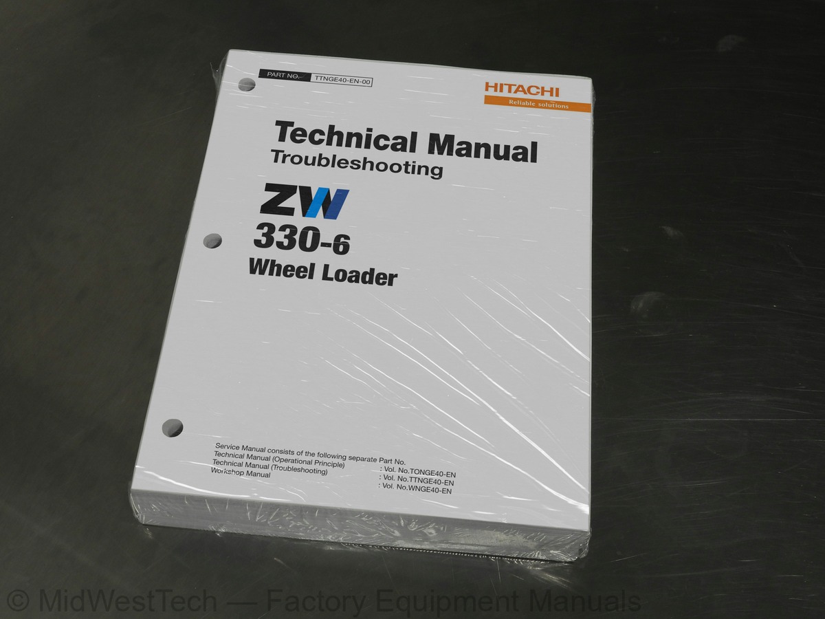
Hitachi ZW330-6 Wheel Loader Troubleshooting Technical Service Manual
482 pages · Publication TTNGE40-EN-00
Added to your cart. View cart
- Models
- ZW330-6
- Manual type
- Troubleshooting Technical Service Manual
- Pages
- 482
- Publication
- TTNGE40-EN-00
- Condition
- Brand new
What's inside
From the manual's own table of contents: 176 topics. See sample pages (PDF, 539 KB)
- Operational Performance Tests
- Preparation for Performance Tests
- Operational Performance Standard Table
- Sensor Activating Range
- Engine Speed
- Travel Speed
- Parking Brake Function Check
- Service Brake Function Check
- Service Brake Wear Amount
- Clearance
- Hydraulic Cylinder Cycle Time
- Cylinder Drift Check
- Bucket Levelness
- Control Lever Operating Force
- Control Lever Stroke
- Setting Pressure)
- Set Pressure
- Solenoid Valve Adjustment Procedure
- Main Pump Delivery Pressure
- Loading Circuit Main Relief Set Pressure
- Procedure
- Steering Circuit Pilot Pressure
- Steering Circuit Main Relief Set Pressure
- Overload Relief Valve Set Pressure
Show all 176 topics
- Service Brake Pressure (Front and Rear)
- Parking Brake Pressure
- Brake Accumulator Pressure
- Accumulator Pressure
- Number of Brake Pedal Applications
- Accumulator Charge Time
- Brake Warning Pressure (Pressure-Decreasing)
- Brake Warning Pressure (Pressure-Increasing)
- Transmission Clutch Pressure
- Transmission Clutch Pack Combination
- Torque Converter Pressure
- Rewrite of Aftertreatment Device Serial No
- Transmission Learning
- Lift Arm Angle Sensor Learning
- Digging Position Adjustment
- Introduction
- Diagnosis Procedure
- Electric System Inspection
- Precautions for Inspection and Maintenance
- Instructions for Disconnecting Connectors
- Fuse Inspection
- Fuse Box A
- Fuse Box B
- Fusible Link Inspection
- Battery Voltage Check
- Alternator Check
- Continuity Check
- Voltage and Current Measurement
- 24-Volt Circuit
- 5-Volt Circuit
- Check by False Signal
- Test Harness
- Surge Voltage and Surge Suppression Diodes
- Outline
- Operating Procedures of Service Menu
- How to display service menu
- Engine Output Restriction Suspend
- Troubleshooting
- Monitoring
- List of Monitoring Item
- Controller Version
- Issued Warning Record
- List of Alarm
- Communication Terminal Status
- List of Communication Terminal Status
- Machine Setting
- Aftertreatment Device No
- Engine Tachometer
- DEF Level Gauge
- Coolant Temperature Gauge
- List of Operation Data
- List of Daily Report Data
- List of Frequency Distribution Data
- List of Total Operating Hours
- Snapshot Data
- Communication System
- Main Component
- Electric Component Layout (Overview)
- Electrical System (Cab)
- Controller and Relays
- Right Console
- Monitor and Switches
- Monitor Panel
- Electrical System (Relays)
- Electrical System (Around Hydraulic Oil Tank)
- Electrical System (Around Fuel Tank)
- Engine
- Aftertreatment Device
- Air Cleaner
- Hydraulic Pump
- Main Pump
- Pilot Pump
- Drive Unit
- Transmission and Torque Converter
- Multiple Control Valve
- Brake Charge Valve/Combination Valve
- Flow Regulator Valve
- Brake Valve
- Ride Control Valve
- Emergency Steering Group
- Steering Valve
- Emergency Steering Pump
- Joystick Steering System (Option)
- Joystick Steering Valve
- Pressure Sensor
- Control Unit (JSS)
- Operator's Seat (JSS)
- DEF Tank and DEF Supply Module
- By Using Fault Codes) Procedure
- MPDr. Fault Code Reference Table
- MC Fault Code List
- Controller Hardware Failure
- CAN Data Reception Failure
- Engine Failure
- Pump Failure
- Pilot Failure
- Proportional Solenoid Valve Failure
- Revolution Sensor Failure
- Learning Failure
- Switch Failure
- Temperature Sensor Failures
- Other Sensor Failures
- Alarms on Monitor
- Monitor Controller (Monitor) Fault Code List
- Column Display Controller Fault Code List
- Air Conditioner Controller Fault Code List
- Communication Terminal Fault Code List
- JCU Fault Code List
- ECM Fault Code List
- Column Display Controller Fault Code 115001
- CAN1 Harness Check
- CAN2 Harness Check
- CAN3 Harness Check
- Sensor
- Specification of Axle Oil Temperature Sensor
- Fuel Level Sensor Specifications
- Hydraulic Oil Level Switch
- Brake Oil Pressure Switch
- Troubleshooting Symptom) Procedure
- and Related Parts
- Part Failures
- Engine System
- All Actuator System
- Front Attachment System
- Steering System
- Travel System
- Brake System
- Other System
- Engine System Troubleshooting
- All Actuator System Troubleshooting
- Front Attachment System Troubleshooting
- Steering System Troubleshooting
- Travel System Troubleshooting
- Brake System Troubleshooting
- Other System Troubleshooting
- Exchange Inspection
- Air Bleeding Procedures for Brake (Axle)
- Component Layout
- Functions of Main Parts
- Faulty cooling
- Faulty heating
- Faulty air vent switch
- Faulty fresh/re-circulated air selection
- Ambient temperature higher or lower
- Noise
- Blower motor does not operate
- Compressor clutch does not operate
- Cooling circuit check by using manifold gauge
- Work after Replacing Components
- Refill Compressor Oil
- Charge Air Conditioner with Refrigerant
- Hose and Pipe Tightening Torque
Inside this manual
Real pages from this troubleshooting technical service manual (482 pages). Open the sample pages (PDF, 538 KB)
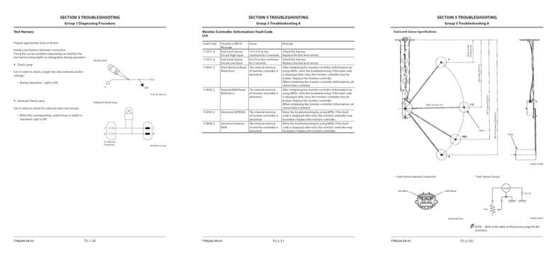
- Diagram, page 148: Group 1 Diagnosing Procedure
- Troubleshooting, page 253: Monitor Controller (Information) Fault Code
- Specifications, page 323: Fuel Level Sensor Specifications
Other manuals for this machine
Save 10% on 2 manuals, 15% on 3 or more. Other manuals for the ZW330-6 are listed below. Editions cover different serial number ranges: check the serial coverage and tick only the ones that match your machine.
Added to your cart. View cart
This is a service manual
Here's how it compares to the other manual types.
Service manual
Factory repair procedures and technical information such as specifications, troubleshooting, and wiring and hydraulic diagrams, for the models and systems the manual covers. See What's inside for its topics.
Operator's manual
Safe operation, controls, maintenance schedules, lubrication points, inspections, and basic checks. Repair procedures are in the service manual.
Parts manual
Illustrated diagrams with factory part numbers for identifying components and ordering parts. Repair procedures are in the service manual.
Engine service manuals are sometimes sold separately, since certain machine models were offered with more than one engine option.
What it's used for
Factory manual for in-house farm and construction shop use. Straightforward, complete, and easy to follow. It contains the OEM information dealership service departments and parts counters use to diagnose problems, identify components, and perform maintenance or repairs correctly.
Service shops and owner/operators who repair their own equipment
Identifying correct parts and seeing how assemblies come apart and go back together
Keeping equipment running with less downtime
Factory manual, 482 pages
Quantity one is the manual described above.
Fast free USA shipping
Ships in 1 business day.
60-day returns
Free if the mistake is ours. A manual ordered in error must come back unopened in its shrink-wrap; you pay return shipping and a 20% restocking fee applies. Return policy
Binder not included
Manuals over about 300 pages may need a standard 3-ring binder, which you can buy locally to keep the pages organized for shop use.
Questions about model, serial number, engine coverage or contents? Contact us before purchasing and we'll help confirm it's the right manual. Please verify the manual type, machine model, serial number range and engine coverage before purchasing: manuals ordered in error carry a 20% restocking fee (return policy).