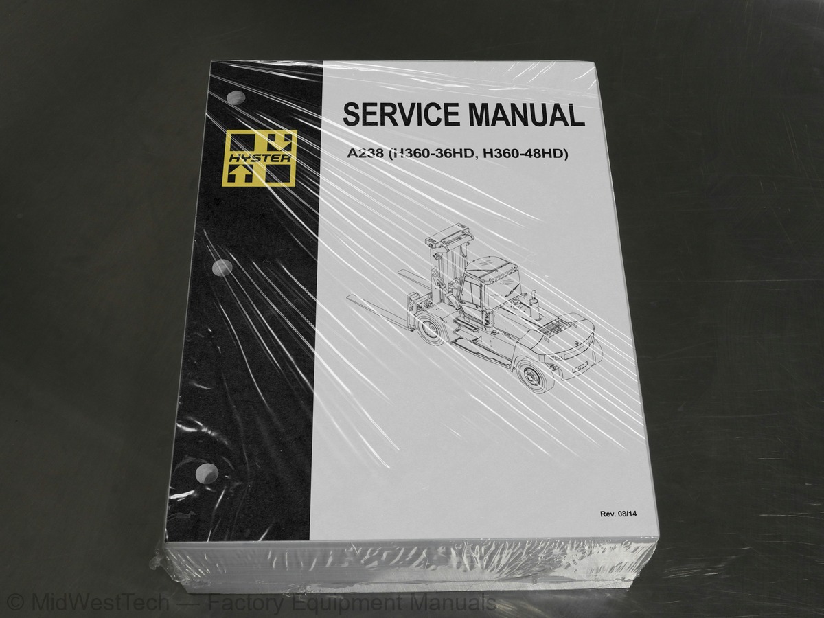
Hyster A238 (H360-36HD, H360-48HD) Heavy Duty Forklift Service Manual
1,001 pages · Publication A238
Added to your cart. View cart
- Models
- A238 (H360-36HD, H360-48HD)
- Manual type
- Service Manual
- Pages
- 1,001
- Publication
- A238
- Condition
- Brand new
What's inside
From the manual's own table of contents: 1 sections, 470 entries. See sample pages (PDF, 358 KB)
General288 topics
- General
- Threaded Fasteners
- Nomenclature, Threads
- Strength Identification
- Cotter (Split) Pins
- Fastener Torque Tables
- Conversion Table
- Series Code / Model Designation Reference Table
- Finding Fault Code Information
- Fault Codes
- Normal Mode
- Fault Log Mode
- Access
- Exit
- Clear
- Electronic Throttle Calibration
- Electronic Throttle Calibration Procedure
- Description of Operation
- Cab Structure
- Cab Tilt System
- Cab Tilt System, Raise
- Cab Tilt System, Lower
- Oil Filling for Cab Tilt System
- Raising and Lowering Cab
- Raise Cab
- Lower Cab
- Cab Door Assembly
- Cab Door
- Remove
- Install
- Door Hinge
- Door Striker Pin
- Door Striker Pin Adjustment
- Door Latch
- Door Handle
- Door Release
- Door Push Button
- Electric Tilt Pump
- Hand Pump
- Cab Tilt Cylinder
- Disassemble
- Clean
- Inspect
- Assemble
- Latch
- Brake and Inching Pedals
- MCC Heater and Air Conditioner
- Heater System
- Air Conditioning
- Dryer
- Compressor Lubrication
- Control Systems, Sensors, and Switches
- Climate Control
- Description
- Service Menu
- Set Up
- View 1 and View 2
- Error List
- Statistics
- Temperature Sensors
- Troubleshooting
- Water Valve
- Standard Heater Assembly
- Standard Heater Parts Replacement
- Heater Core
- Blower
- Push/Pull Cable Replacement
- Water Valve Cable
- Heater/Air Conditioner Assembly
- Heater/Air Conditioner Parts Replacement
- Vent Door
- Evaporator Core
- Torque Converter
- Operational Phases
- Operation
- Hydraulic Operation
- Cooling and Lubrication
- Control System
- Transmission Control Unit (TCU)
- Operating Modes
- Substitute Clutch Control
- Limp-Home Mode
- Transmission Shut Down Mode
- TCU Shut Down Mode
- Transmission Exceed Codes
- Self Test
- Fault Rectification
- Hydraulic Control Valve
- Hydraulic Control Valve Repair
- Solenoid Replacement
- Pressure Check
- Pressure Specifications
- Speed and Temperature Sensors
- Speed Sensors
- Test
- Shift Lever
- Pedal MONOTROL®
- ZF Transmission Test and Calibration
- Transmission Test and Calibration
- Precautions
- Stall Test
- Stall Test Procedure
- Inch Pedal Calibration
- Calibration
- Brake and Inch Pedal Adjustment
- Inch Sensor Adjustment
- Preparation
- Special Tools List
- Transmission Repair
- Transmission Housing, Disassemble
- Oil Pump, Disassemble
- Forward Clutch, Disassemble
- Reverse Clutch, Disassemble
- First Speed Clutch, Disassemble
- Second Speed Clutch, Disassemble
- Third Speed Clutch, Disassemble
- Input Shaft, Disassemble
- Clean and Inspect
- Housings
- Oil Seals and Gaskets
- Bearings
- Gears and Shafts
- Input Shaft, Assemble
- Third Speed Clutch, Assemble
- Second Speed Clutch, Assemble
- First Speed Clutch, Assemble
- Reverse Clutch, Assemble
- Forward Clutch, Assemble
- Oil Pump, Assemble
- Transmission Housing, Assemble
- Transmission Oil Filter Assembly Replacement
- Control Valve Replacement
- Control Valve Repair
- Basic Principles of Flow Control Systems
- Orifice (Fixed/Variable)
- Basic Principle
- Pressure Compensated Flow Control Valve
- Pressure Compensated Flow Control Valve Functional Description
- Priority Valve
- Priority Valve Functional Description
- Load Sense (LS)
- Load Sense Functional Description
- Example 1
- Example 2
- Basic Principles of Pressure Control Systems
- Direct Acting Relief Valves
- Direct Acting Relief Valve Functional Description
- Two-Stage Relief Valve (Pilot Operated Relief Valve)
- Two-Stage Relief Valve (Pilot Operated Relief Valve) Functional Description
- Unloading Valve (Accumulator Charging Valve)
- Unloading Valve (Accumulator Charging Valve) Functional Description
- Counterbalance Valve
- Counterbalance Valve Functional Description
- Pressure Reducer Valve
- Pressure Reducer Valve Functional Description
- Steering System Main Component Identification
- Description and Operation
- Steering System
- Introduction
- Hydraulic Oil Flow Path
- Fundamentals
- Component Validation for Correct Operation
- Steering Control Unit
- Steering Control Valve
- Two-Stage Relief Valve (Pilot-Operated Relief Valve)
- Two-Stage Relief Valve (Pilot-Operated Relief Valve) Functional Description
- Pilot-Operated Selector Valves
- Function Description
- Pump Pressure Free Flow Side
- Function Pressure Blocked Flow Side
- Component Location and Identification
- Main Control Valve
- Flow Path
- Main Manifold
- Priority Valve (A)
- Component Functionality Test
- Check Valve (I)
- Control Valve
- Analog Inputs
- Levers and Joysticks
- Sensors
- Temperature Sensor
- Pressure Sensor
- Digital Inputs
- Switches
- Interrupts
- CAN Bus Communication
- Output Signals
- Analog Outputs
- Digital Outputs
- Programmed Features
- Anti-Stall (Standard)
- Temperature Protection (Standard)
- Low Temperature Protection (Standard)
- High Temperature Protection (Optional)
- Dynamic Control (Optional)
- Loaded Speed Reduction (Optional)
- Settings
- Adjustable Parameters
- Truck Configuration Screen
- Mode Definition Responsiveness (Smooth, Medium, and Rapid)
- Set Default Flow Settings Screen
- Features Screen
- Loaded Speed Reduction Screen
- Flow Settings Screen
- General Functions of the Interface
- Main Functional Requirements
- What is Needed for the Hydraulic User Interface Program
- Installation of the Program
- Start Screen
- Reminder Screen
- Basic Screen Layout of the Hydraulic User Interface Program
- Mode Definition Screen
- Default Flow Settings Screen
- Load Moment Interrupt Screen
- Dynamic Control Screen
- Temperature Protection Screen
- Anti-Stall Screen
- Calibration Screen
- Calibrating the Connected Levers/Joystick Without the Interface Software
- Calibrating the Connected Levers/Joystick With the Interface Software
- Profile Configuration Screen
- Cooling System Description
- Cooling Cores
- Fan Clutch
- Fan Clutch Engagement
- Shroud
- Engine Cooling System
- Water Pump
- Thermostat
- Expansion Tank And Radiator Cap
- Cab Heater
- Coolant
- Charge Air Cooling System
- Transmission Oil Cooling System
- Hydraulic Oil Cooling System
- Hydraulic Oil Cooling
- Oil Filtration and Oil Cooling
- Brake Cooling
- Hydraulic Control System
- Service and Repair
- Cooling System Checks
- Basic Checks
- Coolant Quality Checks
- Coolant Flow Checks
- Cooling Core Efficiency
- Cooling Core Flow Restrictions
- Engine Leak Tests
- External Leak Test
- Check for Coolant Leak Into The Engine Oil Sump
- Combustion Leak Test
- Engine Cooling System Maintenance
- Draining the Engine Cooling System
- Filling the Engine Cooling System
- Flushing the Engine Cooling System
- Cleaning the Engine Cooling System
- Remove and Replace Procedures
- Drive Belt
- Belt Tensioner
- Electrical Schematic and System Description
- Electrical Schematic
- Schematic Location Number
- Electrical Components
- Electrical Wires
- Wire Identification Number
- Electrical Wire Colors
- Wire Harnesses
- Harness Interconnection
- Electrical Connectors
- Connector Types
- Connector Identification
- Connector Pin Numbers
- Connector Description
- Fuses
- Relays
- Flyback Diodes
- CAN (Controller Area Network)
- Diagnostic
- Instrument Panel
- General Fault Finding
- Define the Problem Area
- Identify Possible Causes of Malfunction
- Determine the Most Probable Cause
- Fuse Check
- Wiring Check
- Component Check
- Repair and Test
- Wire Harness Identification and Connector Location
Table 1. Electrical Schematic Index, Tier III181 topics
- Battery, Key Switch
- components
- senders and controls
- lights
- verse alarm
- jumper
- relay, Powered Cab Tilt
- ers, alarms, diagnostics
- solenoid, suspension seat
- ers, Operator Presence
- Auxiliary switches
- switches, timer
- verter, 12V plug
- and Ventilation
- Truck
- sors
- Mast System
- Tilting
- Lifting
- Gland Lubrication
- Pilot Operated Check Valves
- Emergency Lowering Valve
- Lift Chains
- Load Rollers
- Bearing Blocks
- Carriage
- Standard Carriage with Manual Fork Positioning
- Standard Carriage with Hydraulic Fork Positioning
- Integral Side Shift (ISS) Carriage with Pin-Type Forks
- Dual Function Side Shift and Fork Positioning Carriage (DFSSFP)
- DFSSFP Carriage with Quick Disconnect Forks
- DFSSFP Carriage with Integrated Forks
- Forks
- Directional Control Valve
- Alternating Pressure and Tank (P & T)
- Safety Procedures When Working Near Mast
- Remove and Replace
- Pin-Type Forks
- Quick Disconnect DFSSFP Forks
- Integrated DFSSFP Forks
- Fork Hanger for Quick Disconnect Forks
- Fork Positioner Cylinder
- Disassemble - Fork Positioner Cylinder for PinType Carriage
- Assemble - Fork Positioner Cylinder for Pin Type Carriage
- Disassemble - Fork Positioner Cylinder for DFSSFP Carriage
- Assemble - Fork Positioner Cylinder for DFSSFP Carriage
- Side Shift Cylinder
- Weight and Dimensions
- Loading Procedures
- Loading Complete Truck or Basic Truck on a Transport
- Loading Disassembled Components
- Unloading Procedures
- Unloading Complete Truck or Basic Truck from Transport
- Driving On/Off a Trailer
- Unloading Disassembled Components
- Assembly
- Safety Procedures When Working Near the Mast
- Mast
- Carriage Installation
- Mast Inspection
- Mast Condition Check
- Mast Operation Check
- Adjustment
- Lift Chains Adjustment
- Fork Height Adjustment
- Header Hose Tension Adjustment
- Electrical Cable Tension Adjustment
- Tilt Cylinder Backward Tilt Adjustment
- Cab Lights
- Mast Labels
- Lubrication Points
- Empty Seat Engine Shut Down
- Tires and Wheels
- Remove Wheels From Lift Truck
- Pneumatic Tires
- Remove Tire From Two- and Four-Piece Wheel
- Install Tire on Wheel
- Install Tire on Two- and Four-Piece Wheel
- Add Air to Tires
- Solid Rubber Tires
- Wheels, Install
- Moving and Towing
- How to Move a Disabled Lift Truck
- How to Tow the Lift Truck
- Serial Number Data
- How to Tow a Lift Truck
- How to Put Lift Truck on Blocks
- How to Raise Drive Tires
- How to Raise Steering Tires
- How to Clean a Lift Truck
- Truck Maintenance Schedule
- Truck Maintenance Procedures Every 8 Hours or Daily
- How to Make Checks With the Engine Stopped
- Warning and Safety Labels
- Tires and Tire Pressure
- Wheel Nuts
- Forks, Mast, Carriage, Lift Chains, and Attachments
- Header Hose Assembly
- Fuel, Oil, or Coolant Leaks
- Air Intake Piping and Charge Air Piping
- Drive Belts
- Engine Compartment
- Radiator Sections for Engine Coolant, Charge Air Cooler, and Transmission and Hydraulic Oil
- Windshield Washer Fluid
- Hydraulic System Oil
- Engine Oil
- How to Make Checks With Engine Running
- Operator Restraint System
- Safety Belt and Seat Rails
- Steering Column Latch
- Gauges, Lights, and Horn
- Fuses and Relays
- Operator Presence System Disable Switch
- Transmission Calibration Switch
- Windows and Mirrors
- Engine Air Filter
- Fuel Filter/Water Separator
- How to Add Fuel to the Lift Truck
- Coolant Level
- Control Levers and Pedals
- Parking Brake
- Service Brakes
- Lift System Operation
- Attachments
- Transmission
- Operator Presence System
- Transmission Oil
- First Inspection After First 100 Hours of Operation
- Fork Guide Bearing Blocks
- Counterweight Weights
- Lift Truck Weights
- Capacities
- Engine Specifications
- Hydraulic System
- Electrical System
- Tire Sizes
- Mast Speeds
- Torque Specifications, Cummins Diesel
- Lubrication System
- Torque Specifications, General
- Transmission ZF
- Counterweight
- Steering
- Tilt Cylinders
- Air Cleaner
- Air Cleaner Assembly
- Exhaust System
- Exhaust Assembly
- Hood Assembly
- Hydraulic Tank
- Additional Preparations for Repair
- Repair
- Preparations for use After Repair
- Fuel Tank
- Cab Repair
- Engine
- Label Replacement
- Drive Shaft
- Differential
- Planetary Gear Assembly
- Drive Shaft Repair
- Oil Drain and Refill Procedures
- Drain
- Fill
- Brake Housing
- Drive Axle Removal
- Planetary Gear Repair
- Planetary Gear Carrier
- Ring Gear, Ring Gear Hub, and Wheel Hub
- Wheel Hub
- Clean, Inspect, and Repair
- Repairing and Replacing Parts
- Welding
- Ground or Polished Parts
- Parts With Rough Finishes
- Axle Assemblies
- Drying Cleaned Parts
- Preventing Corrosion
- Wheel Bearing Preload, Adjust
- Wet Disc Brake Repair
- Spindle and Brake Cover
Inside this manual
Real pages from this service manual (1,001 pages). Open the sample pages (PDF, 357 KB)
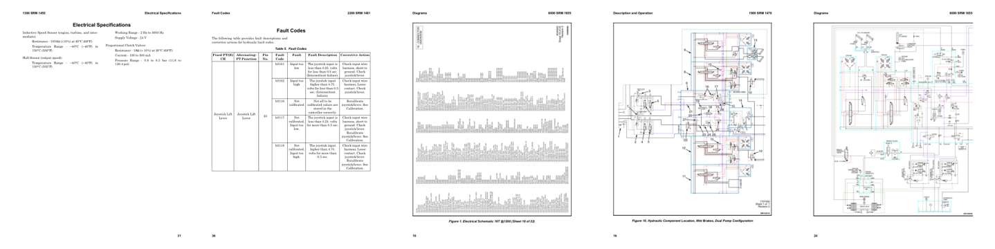
- Specifications, page 238: Electrical Specifications
- Troubleshooting, page 553: Fault Codes
- Diagram, page 793: Figure 1. Electrical Schematic 16T @1200 (Sheet 18 of 22)
- Color page, page 459: Figure 16. Hydraulic Component Location, Wet Brakes, Dual Pump Configuration
- Color page, page 799: Diagrams
This is a service manual
Here's how it compares to the other manual types.
Service manual
Factory repair procedures and technical information such as specifications, troubleshooting, and wiring and hydraulic diagrams, for the models and systems the manual covers. See What's inside for its topics.
Operator's manual
Safe operation, controls, maintenance schedules, lubrication points, inspections, and basic checks. Repair procedures are in the service manual.
Parts manual
Illustrated diagrams with factory part numbers for identifying components and ordering parts. Repair procedures are in the service manual.
Engine service manuals are sometimes sold separately, since certain machine models were offered with more than one engine option.
What it's used for
Factory manual for in-house farm and construction shop use. Straightforward, complete, and easy to follow. It contains the OEM information dealership service departments and parts counters use to diagnose problems, identify components, and perform maintenance or repairs correctly.
Service shops and owner/operators who repair their own equipment
Identifying correct parts and seeing how assemblies come apart and go back together
Keeping equipment running with less downtime
Factory manual, 1,001 pages
Quantity one is the manual described above.
Fast free USA shipping
Ships in 1 business day.
60-day returns
Free if the mistake is ours. A manual ordered in error must come back unopened in its shrink-wrap; you pay return shipping and a 20% restocking fee applies. Return policy
Binder not included
Manuals over about 300 pages may need a standard 3-ring binder, which you can buy locally to keep the pages organized for shop use.
Questions about model, serial number, engine coverage or contents? Contact us before purchasing and we'll help confirm it's the right manual. Please verify the manual type, machine model, serial number range and engine coverage before purchasing: manuals ordered in error carry a 20% restocking fee (return policy).