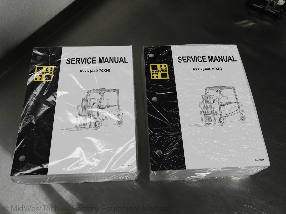
Hyster A276 (J40-70XN) Forklift Service Manual
2,758 pages · Publication A276
Added to your cart. View cart
- Models
- A276 (J40-70XN)
- Manual type
- Service Manual
- Pages
- 2,758
- Publication
- A276
- Condition
- Brand new
What's inside
From the manual's own table of contents: 180 sections, 700 entries. See sample pages (PDF, 362 KB)
General2 topics
- Frame
- Discharging the Capacitors
Overhead Guard Replacement for Lift Trucks E2.2-3.5XN (E45-70XN)2 topics
- Remove
- Install
Battery Restraint and Seat Assembly Repair4 topics
- Operator Restraint System and Seat Assembly
- Operator Restraint System
- Armrest Assembly Repair
- Hood and Seat Latches
Hood and Seat Assembly Replacement for Lift Truck Models E2.2-31 topic
- Ground Test
Hood and Seat Assembly Replacement for Lift Truck Models J2.2-31 topic
- Opening and Closing the Hood
Master Cylinder Repair and Adjustment for Lift Truck J2.2-3.5XN6 topics
- Disassemble
- Clean
- Inspect
- Assemble
- Bench Bleed Master Cylinder
- Install and Adjust
Brake Pedal Components for Lift Truck J2.2-3.5XN (J45-70XN) (A271 topic
- Pedal Adjust
Brake System Air Removal for Lift Truck J2.2-3.5XN (J45-70XN) (A3 topics
- Brake System Air Removal
- Using Pressure Bleed System
- Using Brake Pedal Pressure
Torque Specifications for Lift Truck E2.2-3.5XN (E45-70XN) (A2683 topics
- Overhead Guard
- Counterweight
- Traction Motor
Show all 180 sections
Steering Wheel and Fixed Steering Column Assembly Repair1 topic
- Gear Replacement for Lift Trucks Built Prior to October, 2008
Torque Specifications2 topics
- Steering Control Unit
- Steering Column
Hydraulic Tank9 topics
- Steam Method
- Chemical Method
- Small Leaks, Repair
- Large Leaks, Repair
- Additional Methods for Metal Tank Repair
- Hydraulic Filter Replacement
- Breather Clean and Inspect
- Hydraulic Oil Cooler for Lift Truck Models J4.0-5.0XN (J80-100XN
- Add Hydraulic Oil
Specifications for Lift Truck E2.2-3.5XN (E45-70XN) (A268)1 topic
- Tank Capacity
Specifications for Lift Truck E4.0-5.5XN, E5.0XNS (E80-120XN, E12 topics
- Hydraulic Pump and Motor
- Hydraulic Tank
Manual Hydraulic Control Valve Repair for Lift Truck J1.5-2.0XNT9 topics
- Beginning Steps
- Disassemble Covers, Links, and Levers
- Disassemble Handles and Levers
- Disassemble Manual Control Valve
- Spool Seal Replacement
- Assemble Manual Control Valve
- Assemble Handles and Levers
- Install Covers, Links, and Levers
- Ending Steps
Manual Hydraulic Control Valve Repair E2.2-3.5XN (E45-70XN) (A269 topics
- Remove Control Valve
- Disassemble Valve
- Disassemble Inlet Section
- Disassemble Lift, Tilt, and Auxiliary Sections
- Assemble Lift, Tilt, and Auxiliary Sections
- Assemble Inlet Section
- Assemble Valve
- Install Control Valve
- Ending Steps
Manual Hydraulic Control Valve Repair E4.0-5.5XN, E5.0XNS (E80-19 topics
- Remove Control Valve
- Disassemble Valve
- Disassemble Inlet Section
- Disassemble Lift, Tilt, and Auxiliary Sections
- Assemble Lift, Tilt, and Auxiliary Sections
- Assemble Inlet Section
- Assemble Valve
- Install Control Valve
- Ending Steps
E-Hydraulic Control Valve Repair for Lift Truck J1.5-2.0XNT (J302 topics
- E-Hydraulic Controls
- Replace E-Hydraulic Control Components
E-Hydraulic Control Valve Repair for Lift Truck E2.2-3.5XN (E459 topics
- Initial Steps
- Fitting Removal for Lift Truck E2.2-3.5XN (E45-70XN) (A268)
- Fitting Removal for Lift Truck J2.2-3.5XN (J45-70XN) (A276) and
- Electrical Disconnect and Control Valve Dismount
- Electrical Connect and Control Valve Mount
- Fitting Installation for Lift Truck E2.2-3.5XN (E45-70XN) (A268)
- Fitting Installation for Lift Truck J2.2-3.5XN (J45-70XN) (A276)
- Ending Steps
- Replace E-Hydraulic Control Components
E-Hydraulic Control Valve Repair for Lift Truck E4.0-5.5XN, E5.07 topics
- Initial Steps
- Fitting Removal
- Electrical Disconnect and Control Valve Dismount
- Electrical Connect and Control Valve Mount
- Fitting Installation
- Ending Steps
- Replace E-Hydraulic Control Components
Checks and Adjustments for Lift Truck J1.5-2.0XNT (J30-40XNT) (K7 topics
- Manual Control Valve
- Primary Relief Valve
- Optional Auxiliary Port Relief Valve
- E-Hydraulic Control Valve
- Primary Relief Valve
- Optional Secondary Port Relief Valve
- Hydraulic System Air Removal
Checks and Adjustments for Lift Truck E2.2-3.5XN (E45-70XN) (A266 topics
- External Leakage
- Primary Relief Cartridge
- Secondary Relief Valve
- Primary Relief Valve
- Secondary Relief Valve
- PPRV Pilot Pressure Test
Position Sensor and OPS Check and Adjustment3 topics
- Position Sensor
- (OPS) Operator Presence Solenoid
- Manual Control Valve Re-Calibration
Calibration Procedure1 topic
- Control Valve
Torque Specifications for Lift Truck J1.5-2.0XNT (J30-40XNT) (K13 topics
- Manual Hydraulic Control Valve
- Manual Control Valve Handles and Levers
- Manual Control Valve Covers
Safety Precautions TROUBLESHOOTING PROCEDURES1 topic
- Service Manual Lookup
How To Use This Troubleshooting Manual5 topics
- General Instructions and Safety Information
- How to Use Diagnostic Troubleshooting Manual
- General Instructions
- Conventional Battery Box (CBB) Units
- Drop Battery Box (DBB) Units
Operational Diagnostic Procedures29 topics
- Operational Checkout Procedures
- Key Icon Illuminated
- Wrench Icon Illuminated
- Display Panel (DP) Check
- Operator Presence System Check
- Display Backlight and Icon Power Check
- Light Circuit Check
- Horn Circuit Check
- Backup Alarm Check (If equipped)
- Heater Check (If equipped)
- Brake Pedal Check
- Park Brake Sensor Check
- Park Brake Check
- Brake and Axle Drag Check
- Priority Flow Divider Valve Check
- Mast Cushion Check - Free Lift Cylinder
- Lift Drift Check
- Lift/Tilt Mast Adjustment Check
- Tilt Function Drift Check
- Tilt Racking Check
- Tilt Function, Tilt Lock Piston
- Mast Cushion Check - Main Lift Cylinder
- Mast Channel Check
- Mast Mounting Check
- Chain and Header Hose Adjustment Check
- Chain Sheave Check
- Carriage Adjustment Check
- Carriage Adjustment Check (Standard and Integral Side Shift)
- Steering Relief Valve Low Pressure Check
Traction Motor3 topics
- Principles of Operation
- MASTER DRIVE UNIT
- Poor Tractive Performance
Electrical System16 topics
- Troubleshooting Guidelines and Procedures
- Troubleshooting Guidelines
- Troubleshooting Procedures
- Diagnostic Trouble Codes
- Wiring Reference Data
- Harness Assembly Data
- Electrical System
- General Description
- PRINCIPLES OF OPERATION, COMPONENTS
- PRINCIPLES OF OPERATION, SYSTEM
- None
- DTC None
- Horn Failure
- Lights Inoperative
- Icon Glossary
- Introduction to Icons
Drive Axle/Unit11 topics
- Description
- Principles of Operation
- Service Brake Systems
- Parking Brake Systems
- MONOTROL® Pedal
- One Drive Wheel Will Not Move
- Noise During Operation That Is Not Normal
- Oil Leaks
- Park Brake Does Not Operate Properly
- Motion Inhibited
- Park Brake Troubleshooting Guide
Hydraulic Systems70 topics
- Manual Hydraulic Main Control Valve
- Description
- Manual Hydraulic Control System
- General Description (Open Center Valve)
- Features and Operation
- General Description (Closed Center Valve)
- Features and Operation
- E-Hydraulic Main Control Valve
- Electro-Hydraulic Control System
- General Valve Description
- Features and Operation
- Steering System
- Description
- Steering Control Unit (SCU) Operation
- Abnormal Hydraulic Noise and/or Vibration
- Abnormal Smell/Discoloration/Foaming of Oil
- Cycle Times Too Fast - Fast Actuation (E-Valve)
- Jump/Delay In Lift or Lower Activation After Moving MLM (E-Valve
- Jump/Delay In Auxiliary Function Actuation After Moving MLM (E-V
- Jump/Delay In Tilt Forward or Back Actuation (E-Valve)
- Forks Drop Slightly Before Lifting (E-Valve)
- Forks Lower Without Command (E-Valve)
- Forks Raise or Actuate Without Command (E-Valve)
- Hydraulic Oil Cooler Not Functioning Correctly
- Intermittent Activation (E-Valve) While Commanding Function
- Forks Tilt Forward Without Command (E-Valve)
- Lift/Lower Function Maximum Speed Too Slow (E-Valve)
- Lift Function Will Not Move With MLM Movement (E-Valve)
- Lift/Lower Continues To Move For Awhile After MLM Is Released (E
- Lift/Lower/Auxiliary Function Suddenly Jumps In Middle of Stroke
- Lower Function Will Not Move With MLM Movement (E-Valve)
- Poor Metering on Lift or Lower Functions (E-Valve)
- Auxiliary Function Continues to Move for Awhile After MLM Is Rel
- Auxiliary Function Maximum Speed Too Slow (E-Valve)
- Auxiliary Function or Tilt Back Moves Without Command (E-Valve)
- Auxiliary Function, Tilt Back and/or Tilt Forward Will Not Move
- Tilt Forward or Tilt Back Function Continues to Move for Awhile
- Tilt Forward or Tilt Back Will Not Move With MLM Movement (E-Val
- Too Much MLM Movement (Deadband) to Start Function Moving (E-Val
- Wrong Actuation Operates or Actuation is Backward (E-Valve)
- Actuation Exhibits Slight Movement in Opposite Direction Before
- Auxiliary Function is Slow or Does Not Function (Manual Valve)
- Cycle Times Too Fast - Fast Actuation (Manual Valve)
- Function Continues to Activate After Returning to Neutral
- Lift Function Is Slow or Does Not Function (Manual Valve)
- Tilt Back Function Will Not Operate (Manual Valve)
- Tilt Forward or Tilt Back Will Not Function When Activated (Manu
- No Steering (All Other Hydraulic Functions OK)
- Steering Is Slow or Difficult
- Steering Operation Is Not Smooth
- Steering Wheel End Lock Position Cannot Be Felt by Operator
- Steering Wheel Turns By Itself or Does Not Return To Neutral
- Steering Wheel Turns the Tires in the Wrong Direction
- Actuations Do Not Act Simultaneously
- Oil Leaking/Component Life Too Short
- Abnormal Steer Axle Noise
- Abnormal Steering Wheel Vibration
- Back Lash/Kick Back in Steering Wheel
- Hydraulic Warm-up Procedure
- Primary Relief Valve Test and Adjustment
- Secondary Relief Valve Test and Adjustment
- Hydraulic Pump Flow Test
- Main Control Valve LS Leakage Test (E-Valve)
- Main Control Valve Unloader Margin Test
- E-Hydraulic Valve Leakage Test
- Steering Relief Pressure Test and Adjustment
- Steering Control Unit LS Pressure Test
- Lift Cylinder Leakage Test
- Tilt Cylinder Leakage Test
- Steering Cylinder Leakage Test
Operators Station16 topics
- Operator Station General Description and Principles of Operation
- General Description and Location
- Display Panel
- General Description
- Programming - Menus
- Menu
- Display Menu Flowchart
- Manual Hydraulic Control Levers
- General Description
- System Components
- E-Hydraulic System Interface
- General Description to E-Hydraulic System Interface
- Lighting Control
- General Description
- Cab Panels
- General Description
Front End (Mast) and Chassis56 topics
- Front End, Mast
- Description
- Carriages
- Description
- Principles of Operation
- Mast Mounts
- Description
- Principles of Operation
- Two-Stage Full Free-Lift (FFL) Mast
- Description
- Principles of Operation
- Two-Stage Limited Free-Lift (LFL) Mast
- Description
- Principles of Operation
- Three-Stage Full Free-Lift (FFL) Mast
- Description
- Principles of Operation
- Four-Stage Full Free-Lift (FFL) Mast
- Description
- Principles of Operation
- Cylinder Cushion During Lifting Sequence
- Description
- Principles of Operation
- Cylinder Cushion During Lowering Sequence
- Description
- Principles of Operation
- Tilt and Sideshift Cylinders
- Description
- Lowering Control Valves
- Description
- Principles of Operation
- Chassis
- Description
- Abnormal Channel Wear
- Abnormal Hose Wear
- Abnormal Mast Noise
- Body Panels Making Noise
- External Leakage From Free-Lift or Main Lift Cylinders
- FFL Mast Banging During Phasing
- High Tire Wear - Drive Axle
- High Tire Wear - Steer Axle
- Hoses Not Tracking Correctly
- Integral Sideshift Moving Too Fast
- Integral Sideshift Not Moving or Slow
- Fork Positioner Not Moving or Slow
- Mast is Loose
- Mast Lift Chains Are Loose
- Mast or Carriage Binding
- Mast/Carriage Bounces or is Spongy
- Misphasing of Full Free-Lift Mast
- Overhead Guard Loose or Damaged
- Racking During Lift
- Racking During Tilt
- Truck Feels Unstable
- Truck Wanders, Does Not Track Straight or Steer Well
- Wheel Studs Breaking
Supplementary Data1 topic
- Abbreviations and Acronyms
Periodic Maintenance7 topics
- Serial Number Data
- How to Move Disabled Lift Truck
- How to Tow Lift Truck
- How to Put Lift Truck on Blocks
- How to Raise Drive Tires
- How to Raise Steering Tires
- How to Clean a Lift Truck
Maintenance Procedures Every 8 Hours or Daily23 topics
- How to Make Checks With Key or Keyless Switch OFF
- Tires and Wheels
- Forks
- Inspection of Mast, Carriage, Header Hoses, Lift Chains, and Att
- Safety Labels
- Steering Column Adjustments
- Operator Restraint System
- Emergency Locking Retractor (ELR)
- Seat Adjustments
- Battery Restraint System
- Hood Latch and Hood Release Handle
- Battery
- Hydraulic System
- How to Make Checks With Key or Keyless Switch ON
- Horn, Lights, and Backup Alarm
- Motion Alarm
- Steering System
- Service Brakes
- Automatic Parking Brake
- Hydraulic Control Levers and Pedals
- Direction and Speed Control Pedals
- Lift System Operation
- Oil Leaks
Maintenance Procedures Every 500 Hours or Three Months27 topics
- Forks
- Remove
- Inspect
- Install
- Adjustment
- Header Hose Checks
- Mast Lubrication
- Brake Fluid Check
- Master Cylinder Oil Check
- Operator Presence System Check
- Drive Axle Unit Assembly, Gear Oil Level Check
- Drive Axle Unit Assembly, Wet Brake Oil Level Check
- Tilt Cylinder Rod End Pins
- Lift Chains
- Wear Check
- Lift Chain Lubrication
- Fork Pins and Guides
- Check Upper and Lower Bearings, Integral Sideshift Carriage
- Check Lower Mounting Hook, Integral Sideshift Carriage
- Hydraulic Tank Breather, Check
- Electrical Inspection
- Line Contactor
- Steering Axle
- King Pins and Tie Rods, Lubricate
- Other Lubrication
- Hydraulic Control Levers
- Cab Heater
Maintenance Procedures Every 2000 Hours or Yearly7 topics
- Hydraulic System
- Hydraulic Filter Element, Replace
- Hydraulic Tank Breather, Change
- Service Brakes
- Master Cylinder Oil, Change
- Integral Sideshift Carriage, Replace Upper and Lower Bearings
- Steer Wheel Bearings, Lubricate
Maintenance Procedures Every 4000 Hours or Two Years7 topics
- Hydraulic Oil Change
- Steering Direction Sensor Inspection
- Fixed Steering Column
- Telescopic Steering Column
- Telescopic Steering Column Lubrication
- Drive Axle Unit Assembly, Gear Oil Change
- Drive Axle Unit Assembly, Wet Brake Oil Change
Battery Maintenance6 topics
- How to Charge Battery
- Rapid Charge
- How to Change Batteries
- General
- Remove the Battery
- Install the Battery
Lift and Tilt System Leak Check2 topics
- Lift Cylinder Leak Check
- Tilt Cylinder Leak Check
Safety Procedures When Working Near Mast1 topic
- WHEN WORKING NEAR THE MAST ALWAYS
Wheels and Tires10 topics
- Pneumatic Tires Repair
- Remove Wheels From Lift Truck
- Remove Tire From Wheel
- Install Wheel in Tire
- Add Air to Pneumatic Tires With Tube
- Wheels, Install
- Solid Rubber Tires on Pneumatic Wheels, Change
- Remove Tire From Wheel
- Install Tire on Wheel
- Wheels, Install
Counterweights2 topics
- Specifications
- Turning Radius
Mast Speeds2 topics
- Drive Axle, Speed Reducer, And Differential
- Masts
AC Motor Repair2 topics
- Discharging the Capacitors for Lift Truck Models E30-40HSD 2 (B2
- Discharging the Capacitors (All Other Models)
Traction Motor Repair30 topics
- Remove
- Disassemble
- Electrical Connector Repair or Replacement
- Clean
- Inspect
- Assemble
- Install
- Remove
- Disassemble
- Electrical Connector Repair or Replacement
- Clean
- Inspect
- Assemble
- Install
- Remove
- Disassemble
- Clean
- Inspect
- Assemble
- Install
- Remove
- Disassemble
- Electrical Connector Repair or Replacement
- Clean
- Inspect
- Assemble
- Install
- Remove
- Clean
- Install
Hydraulic Motor Repair36 topics
- Remove
- Disassemble
- Electrical Connector Repair or Replacement
- Clean
- Inspect
- Assemble
- Install
- Remove
- Disassemble
- Electrical Connector Repair or Replacement
- Clean
- Inspect
- Assemble
- Install
- Remove
- Disassemble
- Electrical Connector Repair or Replacement
- Clean
- Inspect
- Assemble
- Install
- Remove
- Disassemble
- Electrical Connector Repair or Replacement
- Clean
- Inspect
- Assemble
- Install
- Traction Motor for Lift Trucks J1.5-2.0XNT (J30-40XNT) (K160) an
- Traction Motor for Lift Truck E30-40HSD 2 (B219)
- Hydraulic Motor for Lift Trucks J1.5-2.0XNT (J30-40XNT) (K160) a
- Hydraulic Motor for Lift Truck E2.2-3.5XN (E45-70XN) (A268)
- Hydraulic Motor for Lift Truck J2.2-3.5XN (J45-70XN) (A276)
- Hydraulic Motor for Lift Truck E1.6-2.0XN (E30-40XN) (A269)
- Hydraulic Motor for Lift Truck E30-40HSD 2 (B219)
- Hydraulic Motor for Lift Truck J4.0-5.0XN (J80-100XN) (A970) and
Window Replacement15 topics
- Front Panel
- Remove, Lift Truck Models A1.3XNT, A1.5XNT (D203)
- Clean
- Inspect
- Install, Lift Truck Models A1.3XNT, A1.5XNT (D203)
- Rear Panel
- Remove
- Clean
- Inspect
- Install
- Door Window
- Disassemble Window
- Clean
- Inspect
- Assemble Window
Window Wipers Replacement5 topics
- Front Wiper Assembly
- Remove, Lift Truck Models A1.3XNT, A1.5XNT (D203)
- Clean
- Inspect
- Install, Lift Truck Models A1.3XNT, A1.5XNT (D203)
Cab Component Repair10 topics
- Roof Liner
- Remove
- Clean
- Inspect
- Install
- Top Panel
- Remove, Lift Truck Models A1.3XNT, A1.5XNT (D203)
- Clean
- Inspect
- Install, Lift Truck Models A1.3XNT, A1.5XNT (D203)
Cab Door Assembly9 topics
- Door Assembly
- Remove
- Disassemble Left Door
- Disassemble Right Door
- Clean
- Inspect
- Assemble Right Door
- Assemble Left Door
- Install
Cab Heater5 topics
- Remove
- Clean
- Inspect
- Install
- Troubleshooting
Weather Panel Replacement for Lift Truck Model E2.2-3.5XN (E45-73 topics
- Roof Panels
- Front Screen Panel
- Roof Panels
Inside this manual
Real pages from this service manual (2,758 pages). Open the sample pages (PDF, 361 KB)
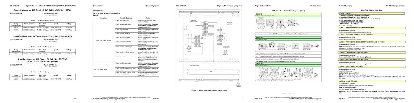
- Specifications, page 491: Specifications for Lift Truck E4.0-5.5XN, E5.0XNS (E80-120XN, E100XNS) (A099)
- Troubleshooting, page 1,961: Drive Axle/Unit
- Diagram, page 2,465: Diagrams, Schematics, or Arrangements
- Color page, page 1,522: Diagnostic Trouble Codes
- Color page, page 2,186: Observed Symptoms
This is a service manual
Here's how it compares to the other manual types.
Service manual
Factory repair procedures and technical information such as specifications, troubleshooting, and wiring and hydraulic diagrams, for the models and systems the manual covers. See What's inside for its topics.
Operator's manual
Safe operation, controls, maintenance schedules, lubrication points, inspections, and basic checks. Repair procedures are in the service manual.
Parts manual
Illustrated diagrams with factory part numbers for identifying components and ordering parts. Repair procedures are in the service manual.
Engine service manuals are sometimes sold separately, since certain machine models were offered with more than one engine option.
What it's used for
Factory manual for in-house farm and construction shop use. Straightforward, complete, and easy to follow. It contains the OEM information dealership service departments and parts counters use to diagnose problems, identify components, and perform maintenance or repairs correctly.
Service shops and owner/operators who repair their own equipment
Identifying correct parts and seeing how assemblies come apart and go back together
Keeping equipment running with less downtime
Factory manual, 2,758 pages
Quantity one is the manual described above.
Fast free USA shipping
Ships in 1 business day.
60-day returns
Free if the mistake is ours. A manual ordered in error must come back unopened in its shrink-wrap; you pay return shipping and a 20% restocking fee applies. Return policy
Binder not included
Manuals over about 300 pages may need a standard 3-ring binder, which you can buy locally to keep the pages organized for shop use.
Questions about model, serial number, engine coverage or contents? Contact us before purchasing and we'll help confirm it's the right manual. Please verify the manual type, machine model, serial number range and engine coverage before purchasing: manuals ordered in error carry a 20% restocking fee (return policy).