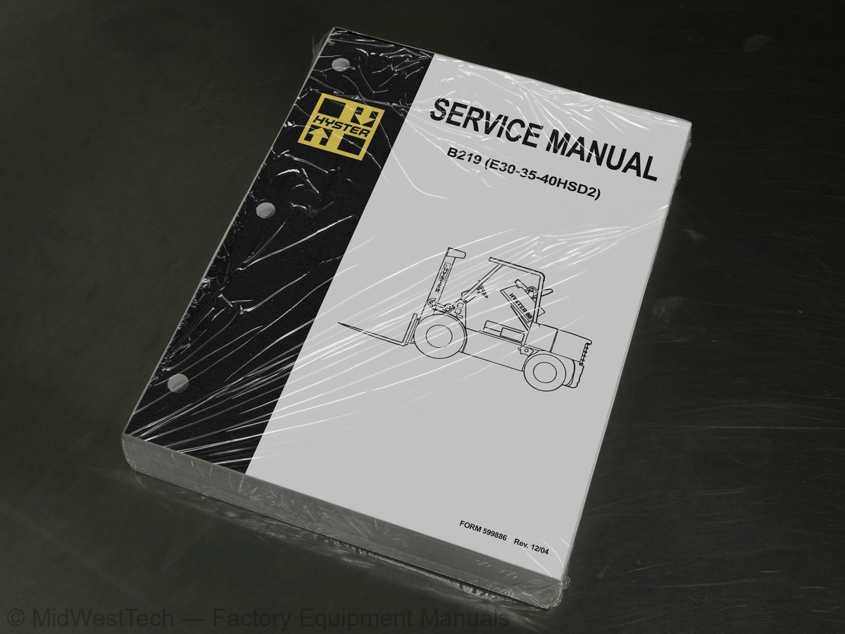
Hyster B219 (E30-35-40HSD2) Forklift Service Manual
758 pages · Publication 599886
Added to your cart. View cart
- Models
- B219 (E30-35-40HSD2)
- Manual type
- Service Manual
- Pages
- 758
- Publication
- 599886
- Condition
- Brand new
What's inside
From the manual's own table of contents: 162 sections, 581 entries. See sample pages (PDF, 179 KB)
INTRODUCTION2 topics
- GENERAL
- DESCRIPTION
DISASSEMBLY AND ASSEMBLY11 topics
- COUNTERWEIGHT
- Removal
- Installation
- OVERHEAD GUARD
- Removal
- Installation
- HOOD AND SEAT REMOVAL
- ENGINE
- Removal
- INSTALLATION
- FUEL TANK
REPAIRS3 topics
- FUEL AND HYDRAULIC TANKS
- Small Leaks
- Large Leaks
OTHER REPAIRS13 topics
- TILT CYLINDER MOUNTS
- STEERING AXLE MOUNT
- LABEL REPLACEMENT
- FAN ASSEMBLY
- Disassembly (S30–120E)
- Disassembly (H60–110E)
- Assembly (Both Series)
- Fan Belt Adjustment
- Installation
- RADIATOR
- Removal
- Installation
- Cleaning and Inspection
TROUBLESHOOTING14 topics
- OPERATION
- The Float System
- The Idle System
- The Main Metering System (GM 6-250)
- The Power System (GM 6-250)
- The Accelerator Pump System
- Choke System
- REMOVAL
- DISASSEMBLY
- Cleaning
- ASSEMBLY
- INSTALLATION
- GOVERNOR (ELECTONIC) (IMPCO Type) (Later Units)
- GOVERNOR (PNEUMATIC) (Early Units)
CHECKS AND ADJUSTMENTS13 topics
- ADJUST THE CHOKE CONTROL
- ADJUST THE IDLE SPEED
- ADJSUT THE IDLE MIXTURE
- ADJUST THE FAST IDLE
- ADJUST THE THROTTLE LINKAGE,(Later Models)
- ADJUST THE THROTTLE LINKAGE,(Early Models)
- GOVERNOR (IMPCO Type) (Later GM 4-153 and 4-181 Engines Only)
- Check the Governor
- GOVERNOR (AISAN Type) (Early GM Engines Only)
- Checks
- Adjustments
- GOVERNOR (HOOF Type) (Early GM Engines Only)
- Adjust the Governor
THE LPG FUEL SYSTEM (IMPCO CA 50, CA 100)51 topics
- Fuel Tank
- Fuel Filter And Fuel Valve Unit
- Vaporizer
- The IMPCO CA 100 Carbureto
- IMPCO CA 50 Carburetor
- The Governor (GM Engines Only)
- Governor With Electronic Controller
- LPG TANK
- Removal
- Installation
- REPLACE THE HOSES
- HYDROSTATIC RELIEF VALVE
- Removal and Installation
- FILTER UNIT
- Replacement Of the Fuel Filter Element
- Replacement of the Diaphragm and Fuel Valve
- VAPORIZER
- Removal
- Disassembly
- Cleaning
- Inspection
- Assembly
- Installation
- CARBURETOR (IMPCO CA 100)
- Removal
- Disassembly
- Cleaning
- Assembly
- Installation
- CARBURETER (IMPCO CA 50)
- Removal
- Disassembly
- Cleaning
- Inspection
- Assembly (See FIGURE 26.)
- Installation
- CHECK THE FILTER UNIT
- CHECK THE VAPORIZER
- Pressure Reducer Valve
- Vapor Valve
- ADJUST THE CARBURETOR
- Idle Mixture
- Idle Speed
- Power Mixture
- ADJUST THE GOVERNOR (GM Engines Only)
- Checks
- Main Adjusting Screw
- Secondary Adjusting Screw
- AISAN Governor
- Adjustment, AISAN Governor
- INSPECTION
CHECKS AND ADJUSTMENT19 topics
- ADJUSTING THE CLUTCH PEDAL HEIGHT
- ADJUSTING THE CLEARANCE OF THE RELEASE MECHANISM
- ADJUSTING THE BY-PASS VALVE FOR COLD AIR
- The Pinion Assembly
- The Differential
- Removing the Transmission (Both Methods)
- Removing The Transmission Without Removing The Drive Axle
- Removing The Transmission With The Drive Axle
- Removing the Selector Rails and Forks
- Removing the Hypoid Ring Gear and Differential
- Removing the Gear Assemblies
- Assembling The Hypoid Pinion and Ring Gear and Differential
- Assembling the Range Countershaft
- Assembling The Forward Countershaft
- Assembling The Forward and Reverse Main Shaft
- Assembling The Input Gear and Range Main Shaft
- Installing the Differential Assembly
- Installing the Selector Rails and Forks
- LINKAGE ADJUSTMENTS
SPECIFICATIONS15 topics
- REPAIRING THE CONTROL VALVE
- Removal and Disassembly
- MONOTROL PEDAL
- Assembly and Installation
- CHECKING THE MONOTROL PEDAL FOR LEAKAGE
- STALL TEST
- MONOTROL LINKAGE
- CHECKING THE OIL PRESSURES
- Clutch Pressure (Check Port "2")
- Inching Pressure (Check Port "2")
- Torque Converter Pressure (Check Port "3")
- Modulator Spool/Clutch Engage Pressure (Check Port "4")
- Bypass Valve for Cold Oil
- CHECKING THE POWERSHIFT ELECTRICAL CIRCUIT
- CHECKING THE CIRCUIT FOR THE DIRECTION CONTROL LEVER
PRESSURE TESTS29 topics
- STEERING AXLES WITH STUB SHAFT MOUNTS
- Removal
- Installation
- ELECTRIC LIFT TRUCK WITH RUBBER MOUNTS
- Removal
- Installation
- ELECTRIC LIFT TRUCK WITH RUBBER MOUNTS (E30-50B, E60BS AFTER AUGUST 1981)
- Removal
- Installation
- WHEELS AND HUBS
- Removal and Disassembly
- Cleaning
- Assembly And Installation
- SPINDLES, BEARING AND TIE RODS
- Removal And Disassembly
- Cleaning
- Assembly And Installation
- STEERING CYLINDER
- Removal And Disassembly
- Cleaning
- Assembly And Installation
- CENTER PIVOT OR RUBBER MOUNTS
- SPINDLE AND HUB
- DESCRIPTION AND OPERATION
- REMOVAL AND DISASSEMBLY
- ASSEMBLY AND INSTALLATION
- ADJUSTING THE RELIEF VALVE
- Steering System
- Lift System
REPAIR10 topics
- HYDRAULIC TANK
- MAIN HYDRAULIC PUMP
- FLOW REGULATOR VALVE
- STEERING CONTROL UNIT
- CONTROL VALVES
- LIFT AND TILT CYLINDERS
- ADJUSTING THE STEERING RELIEF VALVE PRESSURE
- ADJUSTING THE LIFT AND TILT RELIEF VALVE PRESSURE
- ADJUSTING THE TWO-STAGE RELIEF VALVE
- ADJUSTING THE AUXILIARY RELIEF VALVE
Show all 162 sections
ELECTRICAL SCHEMATIC M600A21 topics
- FORKS
- CARRIAGE
- Removal
- SAFETY PROCEDURES WHEN WORKING NEAR THE MAST
- Installation
- MASTS
- Removal
- Disassembly
- Cleaning and Inspection
- Assembly
- CHECKING FOR LEAKS IN THE LIFT SYSTEM
- ADJUSTING THE TILT CYLINDER STROKE AND THE BACKWARD TILT ANGLE
- LIFT CHAIN ADJUSTMENTS
- MAST ADJUSTMENTS
- Guide Shoe Adjustment
- CARRIAGE ADJUSTMENT
- STANDARD MASTS (Mast Assemblies Having Less Than Full Free-Lift.)
- FULL FREE-LIFT MASTS
- THREE-STAGE MASTS
- FOUR-STAGE MASTS
- SEQUENCE VALVE
VISTA THREE-STAGE MASTS1 topic
- MAINTENANCE SCHEDULE
MAINTENANCE PROCEDURES EVERY 8 HOURS OR DAILY16 topics
- CHECK WITH THE ENGINE STOPPED
- Hydraulic Tank
- Air Cleaner
- Engine Oil
- Fuel Filter (Diesel)
- Battery
- Cooling System
- Drive Belts
- Tires And Wheels
- Forks
- Lift Chains
- CHECKS WITH THE ENGINE RUNNING
- Start the engine
- Transmission
- Mast Operation
- Brakes
EVERY 350 HOURS OR TWO MONTHS9 topics
- ENGINE OIL AND FILTER (PERKINS ENGINE)
- ENGINE OIL AND FILTER (GASOLINE ENGINE)
- PRIMARY FUEL FILTER (PERKINS ENGINE)
- BRAKE FLUID
- HYDRAULIC TANK BREATHER
- COOLING FAN
- STEERING AXLE
- UNIVERSAL JOINT
- OTHER LUBRICATION POINTS
EVERY 1000 HOURS OR SIX MONTHS7 topics
- FINAL FUEL FILTER (DIESEL)
- REMOVING AIR FROM THE DIESEL FUEL SYSTEM
- IGNITION SYSTEM (GAS ENGINE)
- PCV VALVE (GAS ENGINE)
- CHECK FOR LEAKS IN THE LIFT AND TILT SYSTEM
- Check The Lift Cylinders For Leaks
- Check The Tilt Cylinder For Leaks
EVERY 2000 HOURS OR YEARLY9 topics
- PCV VALVE (DIESEL ENGINE)
- DIFFERENTIAL
- ADJUSTING THE OIL CLUTCH PEDAL
- OIL FILTER FOR THE POWERSHIFT TRANSMISSION OR THE OIL CLUTCH
- HYDRAULIC SYSTEM
- Changing The Hydraulic Oil Filter
- Changing The Hydraulic Oil
- CHANGE THE GASOLINE FUEL FILTER
- CHANGE THE FUEL FILTER FOR LPG
WHEELS AND TIRES4 topics
- DRIVE TIRES
- STEERING TIRES
- Disassembly
- Assembly
Description4 topics
- Radiator Cap
- Thermostat
- Water Pump
- Fan and Fan Shroud
Cooling System Checks1 topic
- Exhaust Leaks
Radiator Cleaning3 topics
- Drain
- Clean
- Fill
Cylinder Head and Valve Mechanism Repair11 topics
- Cylinder Head, Remove
- Cylinder Head, Disassemble
- Clean and Inspect
- Valves and Valve Seats
- Studs for Rocker Arms
- Hydraulic Valve Lifters, Replace
- Hydraulic Valve Lifters, Clean and Inspect
- Cylinder Head, Assemble
- Cylinder Head, Install
- Valve Clearance, Adjust
- Rocker Arm Cover, Install
Timing Gear Cover Repair2 topics
- Remove
- Install
Camshaft Repair4 topics
- Inspect
- Camshaft Bearing
- Remove
- Install
Lubrication System Repair8 topics
- Oil Sump
- Remove
- Install
- Oil Pump
- Remove
- Disassemble and Repair
- Assemble
- Install
Piston and Connecting Rod Assemblies Repair8 topics
- Connecting Rod Bearings, Replace
- Piston and Connecting Rod Assemblies, Remove
- Piston and Connecting Rod Assemblies, Disassemble
- Piston, Clean and Inspect
- Cylinder Bores, Inspect and Repair
- Piston Rings, Inspect
- Piston and Connecting Rod Assemblies, Assemble
- Piston and Connecting Rod Assemblies, Install
Crankshaft Repair5 topics
- Main Bearings, Replace
- Oil Seal for Rear Main Bearing, Replace (GM 4-181 and 3.0L Only)
- Oil Seal for Rear Main Bearing, Replace (Engines That Have Two-P
- Inspect and Repair
- Main Bearing and Journal Clearance, Check
Flywheel and Flywheel Housing Repair1 topic
- Ring Gear, Replace
Cooling System Repair3 topics
- Coolant Pump
- Fan Drive
- Viscous Fan Drive
Engine Specifications10 topics
- Engine Data
- Cylinder Head
- Hydraulic Valve Lifter
- Camshaft
- Pistons
- Cylinder Bore
- Crankshaft
- Connecting Rods
- Cooling System
- Lubrication System
Operation6 topics
- Lift Spool
- Tilt Spool
- Tilt Backward
- Tilt Forward
- Single-Stage Relief Valve
- Two-Stage Relief Valve
Main Control Valve Repair2 topics
- Remove and Disassemble
- Assemble
Alternator Repair10 topics
- Alternator Type A
- Remove and Disassemble
- Clean
- Assemble
- Install
- Alternator Type B
- Remove and Disassemble
- Clean
- Assemble
- Install
Brushes Circuit Check2 topics
- Delco Alternators
- Motorola Alternators
Diode Bridge Check1 topic
- Delco and Leece-Neville Alternators
High Energy Ignition (HEI) System3 topics
- Disassemble
- Install, If Crankshaft WAS NOT Rotated when Distributor was Remo
- Install, If Crankshaft WAS Rotated when Distributor was Removed
Ignition Coil Replacement6 topics
- Some Four- and Six-Cylinder Models
- Remove
- Install
- V8, Some Four- and Six-Cylinder Models
- Remove
- Install
Ignition Coil Check3 topics
- Coil in Distributor Cap Design
- Separate Coil Design
- Sensing Coil, Check
Drive Axle Repair2 topics
- Disassemble (Type 1 Shown)
- Assemble (Type 1 Shown)
Steering Column Assembly Repair7 topics
- Type A Steering Column Assembly
- Remove and Disassemble
- Assemble and Install
- Type B Steering Column Assembly
- Remove and Disassemble
- Assemble and Install
- Steering Control Unit
Hydraulic Gear Pumps2 topics
- Flow Control Valve
- Relief Valve
Pump Output Check2 topics
- Method No. 1
- Method No. 2
Tilt Cylinder Repair5 topics
- Tilt Cylinders With O-Ring or Single-Lip Seals
- Tilt Cylinders for XM and XMS Models
- Tilt Cylinders for XL, XLS, and XL 3 Models
- Tilt Cylinders for H700-800A and Early Model H700-920B
- Tilt Cylinders Using Chevron Packing
Tilt Cylinder Stroke and Mast Tilt Angle Adjustment2 topics
- Piston Rod Nut
- Retainer
Instrument Panel Indicators and Senders14 topics
- Steering Column Gauges, Meters, and Indicators
- LED Display Panel
- Battery Discharge Indicators
- Brush Wear Indicators
- Motor Temperature Indicators
- LX Series Display Panel
- Hourmeter Functions
- Battery Indicator Function
- Status Code Function
- ZX Series Display Panels
- Display Panel
- Basic Display Panels
- Performance Display
- Brush Wear Indicators
Sender Replacement8 topics
- Fuel Level Sender
- Pressure and Temperature Sender
- Seat Sensor, Operator Presence System (OPS)
- Remove
- Install
- Operator Presence System Module Replacement
- Remove
- Install
Column Mount Display Panel (EV-100/200ZX Motor Controllers) Repl7 topics
- Display Panel Assembly, Replace
- Indicator LEDs
- Battery Indicators
- Digital Display (Performance Display Panel Only)
- Status Code or Performance Level Switches and Indicator LEDs (Pe
- Basic Display Panel, Replace Parts
- Performance Display Panel, Replace Parts
Dash Mount Display Panel (EV100/200ZX Motor Controllers) Replace4 topics
- Remove and Replace
- Meter Specifications
- Sender Specifications
- Meter
Electrical Warning Devices4 topics
- Operator-Controlled Horns
- System Warning Lights, Buzzers, and Bells
- Reverse Warning Horns
- Warning Lights
Replacement5 topics
- Horns or Bells, Replace
- Horn Relay or Buzzer, Replace
- Warning Lights/Bulbs, Replace
- Light Assemblies, Replace
- Flashing Units, Replace
Safety Procedures When Working Near Mast4 topics
- Lowering Control Valve
- Cylinders (General)
- Retainer, Install
- Cylinders (Two-Speed)
Lift Cylinder Repair10 topics
- Lift Cylinder Removal Without Removing Mast
- Standard Masts With Main Lift Cylinder Fastened to Crossmember o
- Standard and Full Free-Lift Masts With Lift Cylinder Fastened to
- Masts That Have Two Cylinders, Main Lift Cylinder and Free-Lift
- Lift Cylinder Installation in Mast
- Standard Masts With Main Lift Cylinder Fastened to Crossmember o
- Standard and Full Free-Lift Masts With Lift Cylinder Fastened to
- Chevron-Style Packing
- Chevron-Style Packing Installation on Piston
- Chevron-Style Packing Installation in Packing Gland
Lift Cylinders for VISTA® Masts3 topics
- Lowering Control Valve
- Main Lift Cylinders
- Free-Lift Cylinder
Inside this manual
Real pages from this service manual (758 pages). Open the sample pages (PDF, 179 KB)
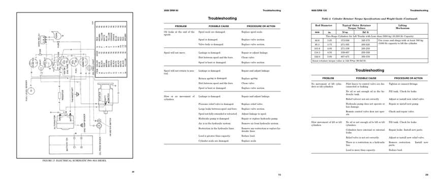
- Diagram, page 264: FIGURE 23. ELECTRICAL SCHEMATIC P60–80A DIESEL
- Troubleshooting, page 451: Troubleshooting
- Specifications, page 693: Troubleshooting
This is a service manual
Here's how it compares to the other manual types.
Service manual
Factory repair procedures and technical information such as specifications, troubleshooting, and wiring and hydraulic diagrams, for the models and systems the manual covers. See What's inside for its topics.
Operator's manual
Safe operation, controls, maintenance schedules, lubrication points, inspections, and basic checks. Repair procedures are in the service manual.
Parts manual
Illustrated diagrams with factory part numbers for identifying components and ordering parts. Repair procedures are in the service manual.
Engine service manuals are sometimes sold separately, since certain machine models were offered with more than one engine option.
What it's used for
Factory manual for in-house farm and construction shop use. Straightforward, complete, and easy to follow. It contains the OEM information dealership service departments and parts counters use to diagnose problems, identify components, and perform maintenance or repairs correctly.
Service shops and owner/operators who repair their own equipment
Identifying correct parts and seeing how assemblies come apart and go back together
Keeping equipment running with less downtime
Factory manual, 758 pages
Quantity one is the manual described above.
Fast free USA shipping
Ships in 1 business day.
60-day returns
Free if the mistake is ours. A manual ordered in error must come back unopened in its shrink-wrap; you pay return shipping and a 20% restocking fee applies. Return policy
Binder not included
Manuals over about 300 pages may need a standard 3-ring binder, which you can buy locally to keep the pages organized for shop use.
Other editions and similar models
Questions about model, serial number, engine coverage or contents? Contact us before purchasing and we'll help confirm it's the right manual. Please verify the manual type, machine model, serial number range and engine coverage before purchasing: manuals ordered in error carry a 20% restocking fee (return policy).