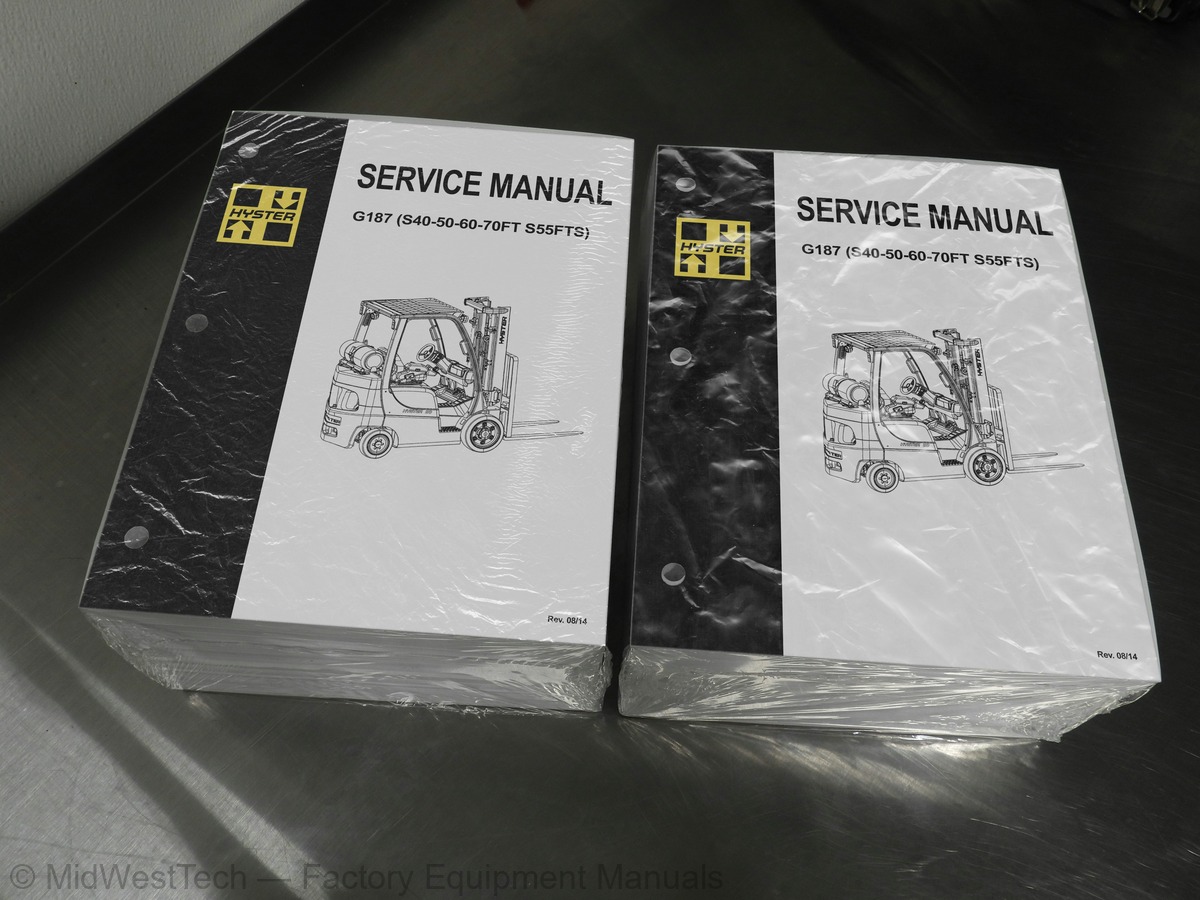
Hyster G187 (S40-50-60-70FT S55FTS) Forklift Service Manual
3,591 pages · Publication G187
Added to your cart. View cart
- Models
- G187 (S40-50-60-70FT S55FTS)
- Manual type
- Service Manual
- Pages
- 3,591
- Publication
- G187
- Condition
- Brand new
What's inside
From the manual's own table of contents: 8 sections, 700 entries. See sample pages (PDF, 431 KB)
General22 topics
- General
- Threaded Fasteners
- Nomenclature, Threads
- Strength Identification
- Cotter (Split) Pins
- Fastener Torque Tables
- Conversion Table
- Group 05 - Operational Checkout
- Group 10 - Principles of Operation
- Group 30 - Observed Symptoms
- Group 40 - Tests and Adjustments
- Group 03 - General Maintenance and Diagnostic Data
- Diagnostic Trouble Code (DTC) Chart
- Group 20 - Diagnostic Trouble Codes
- Group 33 - Observed Symptoms-Gear Pump
- Group 35 - Observed Symptoms-Variable Displacement Pump (VDP)
- Group 43 - Tests and Adjustments-Gear Pump
- Group 45 - Tests and Adjustments-Variable Displacement Pump (VDP)
- Group 50 - Abbreviations and Acronyms
- Group 60 - Special Tools List
- Group 70 - Fault Mode Indicator Reference
- Group 80 - Supplier Specification Data
OPERATIONAL DIAGNOSTIC PROCEDURES45 topics
- Operational Checkout Procedures
- DTC Check
- Horn Circuit Check
- Light Circuit Check
- Windshield Washer Wiper Check (If equipped)
- Heater Check (If equipped)
- Dome Light Check (If equipped)
- Circulating (Accessory) Fan Check (If equipped)
- Indicator Light Power Check
- Engine Malfunction Indicator Check
- Cold Start Check (Diesel Engines Only)
- Brake Pedal Check 1-7 Ton Only
- Brake Check 8-9 Ton Only
- Backup Alarm Check (If equipped)
- Operator Presence System Check
- Hydraulic Interlock Check
- Configuration Data File (CDF)]
- Engine Cover Latch Sensor Check (If equipped)
- Brake and Inching Pedal Check
- Park Brake Sensor Check
- Park Brake Check
- Engine Power Check
- Transmission Clutch Check
- Transmission Check
- Transmission Speed Selection Check (If equipped)
- Brake and Axle Drag Check
- Hydraulic Pump Flow Check
- Priority Flow Divider Valve Check
- Steering Relief Valve Low Pressure Check
- Steering Relief Valve High Pressure Check
- Control Valve Load Check Valve (Manual Valve)
- Lift E-Valve Check
- Lift Check (E-Valve)
- Tilt Function Counterbalance Check
- Lift Drift Check
- Tilt Function Drift Check
- Mast Cushion Check (All Except 2-Stage Mast)
- Lift/Tilt Mast Adjustment Check
- Tilt Racking Check
- Chain and Header Hose Adjustment Check
- Mast Mounting Check
- Mast Channel Check
- Carriage Adjustment Check
- Chain Sheave Check
- Carriage Adjustment Check (Standard and Integral Side Shift)
ENGINE45 topics
- Engine Basics
- General Terminology
- Combustion Theory
- Engine Components – Cylinder Block
- Camshaft and Timing Set
- Cylinder Head Assembly
- Valve Train Assembly
- Manifolds
- Air Cleaner/Filter
- Carburetion
- Electronic Fuel Injection (EFI)
- Positive Crankcase Ventilation (PCV)
- Engine Electrical
- Introduction
- Battery Construction
- Conventional Standard Battery
- Maintenance-Free Battery
- Battery Charging
- Battery Fast Charging
- Battery Slow Charging
- Starting System Principles of Operation
- Starting System Components - Ignition Switch
- Starting System Components - Starter Solenoid
- Starting System Components - Flywheel and Ring Gear
- Starting System Components - Starter Motor and Drive
- Charging System - General
- Charging System - Regulator
- Charging System - Theory
- Engine Fuel System/Exhaust and Emissions
- Gasoline System Components - Fuel Tank
- Electronic Fuel Injector (EFI) - General Description
- Port Fuel System Components - ECU
- Port Fuel System Components - Fuel Pump/Filter
- Port Fuel System Components - Fuel Rail
- Port Fuel System Components - Pressure Regulator
- Port Fuel System Components - Fuel Injectors
- LPG Systems General Information
- LPG Fuel Monitoring
- LPG Fuel Properties
- LPG Fuel Tank
- PSI Closed-Loop System
- AISAN Closed-Loop System
- DIESEL PARTICULATE FILTER
- Main Fuel Lockoff Solenoid
- Injector Fuel Lockoff Solenoid
ELECTRICAL SYSTEM19 topics
- Troubleshooting Guidelines and Procedures
- Troubleshooting Guidelines
- Troubleshooting Procedures
- Troubleshooting Procedures, Identification
- Troubleshooting Procedures, Location
- Troubleshooting Procedures, Structure
- Troubleshooting Procedures, Performance
- Diagnostic Trouble Codes
- Wiring Reference Data
- Post 2007 Engine Connections
- Cummins 4.5L
- Harness Assembly Data
- Electrical System
- General Description
- Description
- Principles of Operation, Components
- Principles Of Operation, System
- DTC 523959-3 - Hydraulic Aux 2 Pressure OORH
- DTC 135-16 - Fuel Absolute Pressure Minus (MAP) Too High
DRIVE TRAIN38 topics
- Mechanical Overview
- Engine
- Torque Converter
- Stator
- Turbine
- Pump PTO
- Cast Iron Transmission Chain Drive
- Aluminum Transmission Gear Drive
- Aluminum Transmission Chain Drive
- Spur Gear PTO
- Transmission
- 1.0-5.5 Ton Lift Truck Transmissions
- 6.0-9.0 Ton Lift Truck Transmissions
- Clutch Pack
- Power Flow
- Transmission Hydraulic Schematic
- Transmission Oil Flow
- Control Valve Oil Flow
- Transmission Control System Overview
- Transmission Control System
- Transmission Control Software
- Transmission Control Modes
- Neutral
- Gear Engagement Control
- Normal Forward or Reverse
- Auto-Shift
- 1st Gear Lock
- Inching
- Inch/Brake Overlap Adjustment
- Brake Wear Compensation
- Auto Decel
- Controlled Power Reversal
- Controlled Creep
- Controlled Roll Back
- Travel Speed Limit (Optional)
- Extended Drawbar Pull ( Multi-Speed Only)
- Auto-Speed Hydraulics ( Transmissions Only)
- Transmission Control Hardware
HYDRAULIC SYSTEMS30 topics
- Main Hydraulic System
- Principles of Operation
- Hydraulic Schematics
- Manual Control Valve Schematics
- Electro-Hydraulic Control Valve Schematics
- Manual Hydraulic Control Valve
- Lift Section
- Tilt Section
- Auxiliary Section
- Anti-Stall Feature
- Relief Valves
- Emergency Lowering Valve
- Operator Presence Spool Lockout Mechanism
- Electro-Hydraulic Control Valve
- Inlet Pressure Compensator/Unloader
- Lift/Lower EHPVs
- Tilt and Auxiliary Spool Functions
- Main Relief Valve
- Secondary Relief Valve
- Anti-Stall Function
- Steering System
- Component Locations
- Steering Schematic
- Steering Axle Assembly
- Steering Control Unit
- Hydraulic System with Variable Displacement Pump
- Variable Displacement Pump
- Operation
- Pressure Control
- Flow Compensator
OPERATORS STATION42 topics
- Operator Station General Description and Principles of Operation
- General Description and Location
- Display Switch Cluster (DSC)
- Detailed Description
- Control Inputs, Right Side
- Right Indicator and Warning Group
- LCD Display
- Left Indicator and Warning Group
- Control Inputs, Left Side (Cab Option Only)
- Transmission Control and Braking
- Vehicle System Manager (VSM)
- Display Switch Cluster
- Directional Control
- Inch Brake/Service Brake Pedal
- Parking Brake
- Programming - Menus
- Menus
- Main Menu
- Save and Exit or Exit Without Saving
- Back One Level
- Hourmeters
- View Versions
- Passwords
- Diagnostics
- Setup Travel and Braking
- Setup Hydraulics
- Setup Display
- Setup General Items
- Calibrations
- Manual Hydraulic Control Levers
- System Components
- Lift/Lower
- Tilt
- Auxiliary 1
- Auxiliary 2
- E-Hydraulic System Interface
- E-Hydraulic Control Input Device
- System Modes
- Normal Operation
- Joystick
- Mini-Lever Module (MLM)
- Hydraulic Interlock Mode
FRONT END (MAST) AND CHASSIS24 topics
- Front End, Mast
- Carriages
- Integral Sideshift Carriage
- Mast Mounts
- Two-Stage Limited Free-Lift (LFL) Mast
- Two-Stage Full Free-Lift (FFL) Mast
- Three-Stage Full Free-Lift (FFL) Mast
- Four-Stage Full Free-Lift (FFL) Mast
- Cylinder Cushion During Lifting Sequence
- Cylinder Cushion During Lowering Sequence
- Tilt and Sideshift Cylinders
- Tilt Cylinder
- Sideshift Cylinder
- Lowering Control Valves
- Chassis
- Abnormal Channel Wear
- Abnormal Hose Wear
- Abnormal Mast Noise
- Body Panels Making Noise
- External Leakage From Free-Lift or Main Lift Cylinders
- FFL Mast Banging During Phasing
- High Tire Wear - Drive Axle
- High Tire Wear - Steer Axle
- Hoses Not Tracking Correctly
SUPPLEMENTARY DATA427 topics
- Abbreviations and Acronyms
- Special Tools List
- Fault Mode Indicator (FMI) Reference List
- TSP Reference Tables
- Deutsch Crimping Tool
- How to Strip a Wire for Use With Deutsch Crimping Tool
- How to Crimp With the Deutsch Crimping Tool
- Calibration Test for the Deutsch Crimping Tool
- Deutsch Connectors
- DT, DTM, and DTP Series Connectors
- Connector Receptacle Replacement
- Connector Plug Replacement
- Connector Receptacle Pin Replacement
- Connector Plug Socket Replacement
- HD Series Connectors
- Sealing Plugs
- Metri-Pack Connectors
- Remove and Install
- Micro-Pack Connectors
- Weather-Pack Connectors
- Weather-Pack Terminal Repair
- AMPSEAL Crimping Tools
- AMP Hand Crimping Tool With Certi-Crimp
- Stripping Wire for Use with AMP Hand Crimping Tool
- Insulation Crimp Adjustment
- Maintenance and Inspection for AMP Hand Crimping Tool
- AMP Hand Crimping Tool
- Crimp Height Inspection
- How to use AMP Hand Crimping Tool
- AMP Pro-Crimper II Tool
- Remove and Install Die Set and Locator Assembly
- Stripping Wire for Use With AMP PRO-CRIMPER II Tool
- Contact Support Adjustment
- Crimp Height Adjustment
- Maintenance and Inspection Procedures
- PRO-CRIMPER II Tool
- How to Use AMP PRO-CRIMPER II Tool
- AMPSEAL Connector Assemblies
- Description for Plug Connector Assembly
- Seal Plug
- Contact Crimping
- Contact Removal
- Contact Insertion
- Description for Plug Connector and Header Assembly
- Voltage Reading
- Dash Display Menu Access
- Menu Navigation
- Standard Display
- Passwords Menu
- Password Administration
- Add Password
- Delete Password
- Edit Password
- Other Password Functions
- Operator Passwords - Enable/Disable
- Password Time-Out Delay
- Passwords - Number Wrong to Disable
- Lockout Reset Password
- View Password Log
- VSM Versions
- Dash Display Versions
- Engine Controller Version
- Transmission (Xmsn) Controller Version
- Truck Serial Number
- View Fault Log
- Set Travel and Braking
- Speed Limit
- Acceleration Rate
- Auto-Deceleration Rate
- Set Power Reversal Rate
- Set Inching/Brake Overlap
- Setup Display Menu
- Set Operator Language
- Set Units
- Set Time Format (12/24 Hour)
- Set Daylight Saving Time
- Set Time
- Set Date Format
- Set Date
- Return to Set Tilt Delay/On/Off
- Light Shutdown Time-Out
- Impact Sensor - Enable/Disable
- Impact Sensor - Soft Impact Settings
- Impact Sensor - Hard Impact Settings
- Adjust Impact Sensor Settings
- Initial Adjustment of Soft and Hard Impact Settings
- Readjustment of Soft and Hard Impact Settings
- Impact Sensor - Impact Alarm/Shutdown Reset
- Adding Passwords
- Truck Configuration
- Clear Fault Log
- No-Run Data Display
- Engine Accelerator and Throttle Data Display
- Engine Speeds and Governor Data Display
- Engine Fuel and Emissions Data Display
- Engine General Data Display
- XMSN/Brake Data Display
- Hydraulic Data Display
- General Truck Data Display
- Lift Maximum Speed
- Lower Maximum Speed
- Tilt Maximum Speed
- Auxiliary Function One, Direction A, Maximum Speed
- Auxiliary Function One, Direction B, Maximum Speed
- Auxiliary Function Two, Direction A, Maximum Speed
- Auxiliary Function Two, Direction B, Maximum Speed
- Auxiliary Function Three, Direction A, Maximum Speed
- Auxiliary Function Three, Direction B, Maximum Speed
- Lift/Lower Ramp Rate
- Hydraulic Auxiliary Ramp Rate
- Hydraulic Input Device
- Auxiliary Solenoid
- Dual Function
- Set Service Language
- Proc_Cal_001: Service Password Entry
- When to Perform
- Why Perform
- How to Perform
- Proc_Cal_002: Hydraulic Valve Calibration Warm Up and Air Bleed
- Calibration Order
- Proc_Cal_003: Save and Exit
- Proc_Cal_004: Lift Valve Output Threshold
- Proc_Cal_005: Lower Valve Output Threshold
- Proc_Cal_006: Tilt Back Valve Output Threshold
- Proc_Cal_007: Tilt Forward Valve Output Threshold
- Proc_Cal_008: Aux 1 Dir A Valve Output Threshold
- Proc_Cal_009: Aux 1 Dir B Valve Output Threshold
- Proc_Cal_010: Aux 2 Dir A Valve Output Threshold
- Proc_Cal_011: Aux 2 Dir B Valve Output Threshold
- Proper Flushing after Major Hydraulic Repairs
- The Phases of Wear
- Causes of Hydraulic System Failure
- Progression of Contaminant Caused Hydraulic System Failure
- Hydraulic System Flushing Techniques
- Double Oil and Filter Change
- Mechanical Cleaning
- Cleaning of Components
- How to Clean Tubes and Hoses
- Filter Caddy
- Start-Up Procedure for Cleaned System
- Contaminated Oil Coolers
- Additional Filter Caddy Functions
- How to Handle Different Fluids
- Water Removal Filters
- Fluid Conditioning and System Flushing Procedures
- Operation of the Filter Caddy
- Filter Caddy operation
- Fluid Conditioning Procedure
- Filter Caddy Start-Up
- System Flushing Procedure
- Component Cleaning Procedure
- Reservoir Cleaning Procedure
- Cylinder Cleaning Procedure
- Hose and Tube Cleaning Procedure
- Valve Cleaning Procedure
- Front-End Attachment Cleaning Procedure
- System Start-Up and Flushing
- Reservoir Fluid Cleaning Times
- Dealing With Different Fluid Types
- Cleaning Procedure After Switching Fluids (Cross Contamination Flushing)
- Filter Caddy Maintenance
- Servicing the Strainer
- DC Motor
- Hydraulic Oil Sampling Method and Procedure
- Hydraulic Oil Sampling Method
- Objective
- General Guidelines
- Synopsis
- Hydraulic Oil Analysis Report Guidelines
- Sampling Conditions
- Equipment
- Sampling Procedure
- Hydraulic Oil Sampling
- Sample Labeling
- Results Documentation
- Safety Procedures When Working Near Mast
- Main Lift Cylinder Repair
- Remove
- Disassemble
- Clean
- Inspect
- Assemble
- Install
- Main Lift Cylinder Leak Check
- Free-Lift Cylinder
- Tilt Cylinder Repair
- Tilt Cylinder Adjustment
- Tilt Cylinder Leak Check
- Integrated Sideshift Cylinder Repair
- Fork Positioner Cylinder Repair
- Fork Positioner Cylinder Adjustment
- Seal Kit Installation
- External Installation (Seal and Backup Ring)
- Internal Installation (Piston Rod Assembly)
- Torque Specifications
- Main Lift Cylinders
- Tilt Cylinders
- Integrated Sideshift Cylinder
- Fork Positioner Cylinder
- Fork Replacement
- Standard Carriage and Integral Sideshift Carriage
- Checks
- Fork Positioner Carriage
- Carriages Repair, Two-Stage LFL Mast
- Standard Carriage
- Clean and Inspect
- Fork Positioner Hydraulic Hose Adjustment
- Two-Stage LFL Mast Repair
- Mast With Serial Number F507
- Header Hoses
- Installation
- Adjustment
- Mast With Serial Number F562
- Header Hose Installation and Adjustment
- Carriages Repair, Three-Stage FFL Mast
- Hood, Seat, and Side Covers Replacement
- Steering Column
- Steering Column Repair
- LPG Tank and Bracket Assembly
- Counterweight Replacement
- Overhead Guard Replacement
- LED Tail, Backup, and Brake Lights, Replace
- Operator Restraint System Replacement
- Emergency Locking Retractor (ELR)
- Engine Replacement
- Transmission Replacement
- Remove Transmission with Iron Housing
- Install Transmission with Iron Housing
- Remove Transmission with Aluminum Housing
- Install Transmission with Aluminum Housing
- Throttle Pedal and Cable Adjustment
- Mazda Gas/LPG Engines With Basic Power Shift Transmission and Electronic Transmission
- Mazda Gasoline Engine With Electronic Transmission
- Throttle Pedal Stop Adjustment
- Yanmar Diesel Engine With Basic Power Shift Transmission
- Yanmar Diesel Engine With Electronic Throttle
- Exhaust System Repair
- Lift Trucks With Counterweight Exhaust System
- Mazda Gas and LPG Engines
- Kubota LPG Engines
- Yanmar Diesel Engine
- Remove and Disassemble
- Assemble and Install
- Lift Trucks With Overhead Exhaust System
- Serial Number
- Engine Removal and Installation
- Cylinder Head, Camshaft, and Valve Mechanism Repair
- Inspect and Repair
- Cylinder Head
- Rocker Shaft Assembly
- Camshaft
- Valve Guides
- Valve Seats
- Valves
- Valve Springs
- Crankshaft and Main Bearings Repair
- Crankshaft
- Main Bearings
- Pistons and Connecting Rods Repair
- Pistons
- Piston Rings
- Connecting Rods and Bearings
- Cylinder Block Repair
- Oil Pump Repair
- Cooling System Repair
- Thermostat
- Replace
- Fan Assembly
- Water Pump
- Flywheel and Ring Gear Repair
- Valve Adjustment
- Fan Belt Installation
- Thermostat Repair
- Thermostat Operation Check
- Water Pump Repair
- Lubrication System Repair
- Oil Pan and Oil Pickup, Remove
- Oil Pan and Oil Pickup, Inspection
- Oil Pump, Remove
- Oil Pump, Inspection
- Rotor Lobe Clearance
- Rotor Cover Clearance
- Oil Pump, Assemble and Install
- Oil Pan and Oil Pickup, Assemble and Install
- Cylinder Head Repair
- Valve Guides and Seats
- Valve Lapping
- Valve Guide, Replacement
- Valve Seats, Inspection and Repair
- Valve and Valve Seat Correction
- Gear Case, Timing Gears, and Camshaft
- Gear Case
- Fan Drive Pulley, Remove
- Fan Drive Pulley, Install
- Gear Case, Remove
- Gear Case, Install
- Timing Gears
- Oil Pump, Install
- Crankshaft Oil Slinger, Remove
- Crankshaft Oil Slinger, Install
- Idler Gear, Remove
- Idler Gear, Install
- Camshaft, Remove
- Camshaft, Install
- Piston and Connecting Rod Assemblies Repair
- Cooling System Checks
- Exhaust Leaks Into Cooling System
- Water Flow Restrictions in Radiator
- Radiator Hoses
- Flushing the Cooling System
- Cooling System, Clean
- Radiator Replacement
- Radiator, Remove
- Radiator, Install
- Fan Assembly Replacement
- Fan Removal
- Fan Installation
- LPG Tank and Bracket Replacement
- Remove LPG Tank
- Install LPG Tank
- Remove LPG Bracket
- Install LPG Bracket
- Remove LPG Tank Bracket Alignment Pin
- Install LPG Tank Bracket Alignment Pin
- Fuel Filter Unit Repair
- Fuel Filter Element
- Clean/Inspect
- Fuel Filter Housing
- Electronic Throttle Body Repair
- Electronic Pressure Regulator (EPR) Repair
- LPG Shutoff Valve Assembly
- Fuel Mixer Repair
- Control System
- Engine Control Module (ECM)
- Low LPG Pressure Switch
- LPG Low Level Sensor
- Exhaust System
- Counterweight Exhaust System
- Overhead Exhaust System
- Intake-Air System
- Intake-Air System Manifold Vacuum Check
- Throttle Body
- Intake Manifold
- Fuel System
- Before Repair Procedure
- Fuel Line Safety Procedure
- After Repair Procedure
- Fuel Hose, Install
- Fuel Leakage Check
- Fuel Line Pressure Check
- Fuel Injectors
- Pressure Regulator
- Exhaust Manifold
- Positive Crankcase Ventilation (PCV) Valve
- Oxygen Sensor
- Fuel Level Sensor
- Technical Data
- LPG Fuel Filter Unit Repair
- LPG Fuel Filter Element
- Remove/Disassemble
- Assemble/Install
- LPG Fuel Mixer With Direct Electronic Pressure Regulator (DEPR) Repair
- Engine Control Unit (ECU)
- LPG Converter
- LPG Lock-Off Valve
- Hydraulic Gear Pump
- Charge Pump Repair
- Torque Converter Replacement
- Stator Support Assembly Repair
- Clutch Packs Repair
- Housings
- Clutch Packs
- Forward Clutch Pack
- Reverse Clutch Pack
- Drive Chains and Sprockets
- Proportional and Enable Solenoid Valves
- Proportional Valves
- Enable Solenoid Valve
- Identification Plate
- Drive Axle Removal
- Reduction Gear Assembly
- Reduction Gear Assembly Repair
- Brake Repair
- Wet Disc Brake
- Parking Brake Control Lever
- Differential Repair
- Flange
- Differential Assembly
- Bevel Pinion
- Determine Bevel Pinion Shim Thickness
- Gear Set, Tooth Contact Pattern Check
- Drive Axle Installation
- Special Tools
- Drive Axle Repair
- Differential Assembly From Center Section
- Drive Pinion, Pinion Gear, and Bearings From Center Section
- Drop Box Housing
- Center Section
- Pinion Inner Shim Set, Adjust Thickness (Depth of Pinion)
- Drive Pinion, Pinion Gear, and Bearings Into Center Section
- Differential Assembly Into Center Section
- Ring Gear Backlash, Adjust
- Ring Gear, Runout Check
- Steering Axle Assembly Repair
- Spindles, Bearings, and Tie Rods Repair
- Spindles and Bearings
- Tie Rods
- Steering Cylinder Repair
- Dry Brake System
- Wet Brake System
- Service Brakes Repair (Dry Brake)
- Adjust
- Inching Overlap Adjustment
- Parking Brake Repair
- Master Cylinder Repair
- Remove (Dry Brake)
- Disassemble (Dry Brake)
- Clean and Inspect (Dry Brake)
- Assemble (Dry Brake)
- Bench Bleed Master Cylinder (Dry Brake)
- Install and Adjust (Dry Brake)
- Remove (Wet Brake)
- Disassemble (Wet Brake)
- Clean and Inspect (Wet Brake)
- Assemble (Wet Brake)
- Install and Adjust (Wet Brake)
- Service Brakes Adjustment (Dry Brake)
Inside this manual
Real pages from this service manual (3,591 pages). Open the sample pages (PDF, 430 KB)
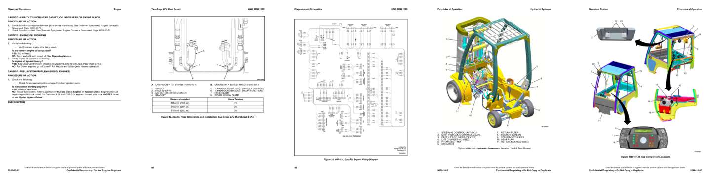
- Troubleshooting, page 311: CAUSE D - FAULTY CYLINDER HEAD GASKET, CYLINDER HEAD, OR ENGINE BLOCK.
- Specifications, page 2,291: DIMENSION = 100 ±10 mm (4.0 ±0.40 in.)
- Diagram, page 3,391: Figure 35. GM 4.3L Gas PSI Engine Wiring Diagram
- Color page, page 1,429: STEERING CONTROL UNIT (SCU)
- Color page, page 1,680: Figure 9060-10-25. Cab Component Locations
This is a service manual
Here's how it compares to the other manual types.
Service manual
Factory repair procedures and technical information such as specifications, troubleshooting, and wiring and hydraulic diagrams, for the models and systems the manual covers. See What's inside for its topics.
Operator's manual
Safe operation, controls, maintenance schedules, lubrication points, inspections, and basic checks. Repair procedures are in the service manual.
Parts manual
Illustrated diagrams with factory part numbers for identifying components and ordering parts. Repair procedures are in the service manual.
Engine service manuals are sometimes sold separately, since certain machine models were offered with more than one engine option.
What it's used for
Factory manual for in-house farm and construction shop use. Straightforward, complete, and easy to follow. It contains the OEM information dealership service departments and parts counters use to diagnose problems, identify components, and perform maintenance or repairs correctly.
Service shops and owner/operators who repair their own equipment
Identifying correct parts and seeing how assemblies come apart and go back together
Keeping equipment running with less downtime
Factory manual, 3,591 pages
Quantity one is the manual described above.
Fast free USA shipping
Ships in 1 business day.
60-day returns
Free if the mistake is ours. A manual ordered in error must come back unopened in its shrink-wrap; you pay return shipping and a 20% restocking fee applies. Return policy
Binder not included
Manuals over about 300 pages may need a standard 3-ring binder, which you can buy locally to keep the pages organized for shop use.
Other editions and similar models
Questions about model, serial number, engine coverage or contents? Contact us before purchasing and we'll help confirm it's the right manual. Please verify the manual type, machine model, serial number range and engine coverage before purchasing: manuals ordered in error carry a 20% restocking fee (return policy).