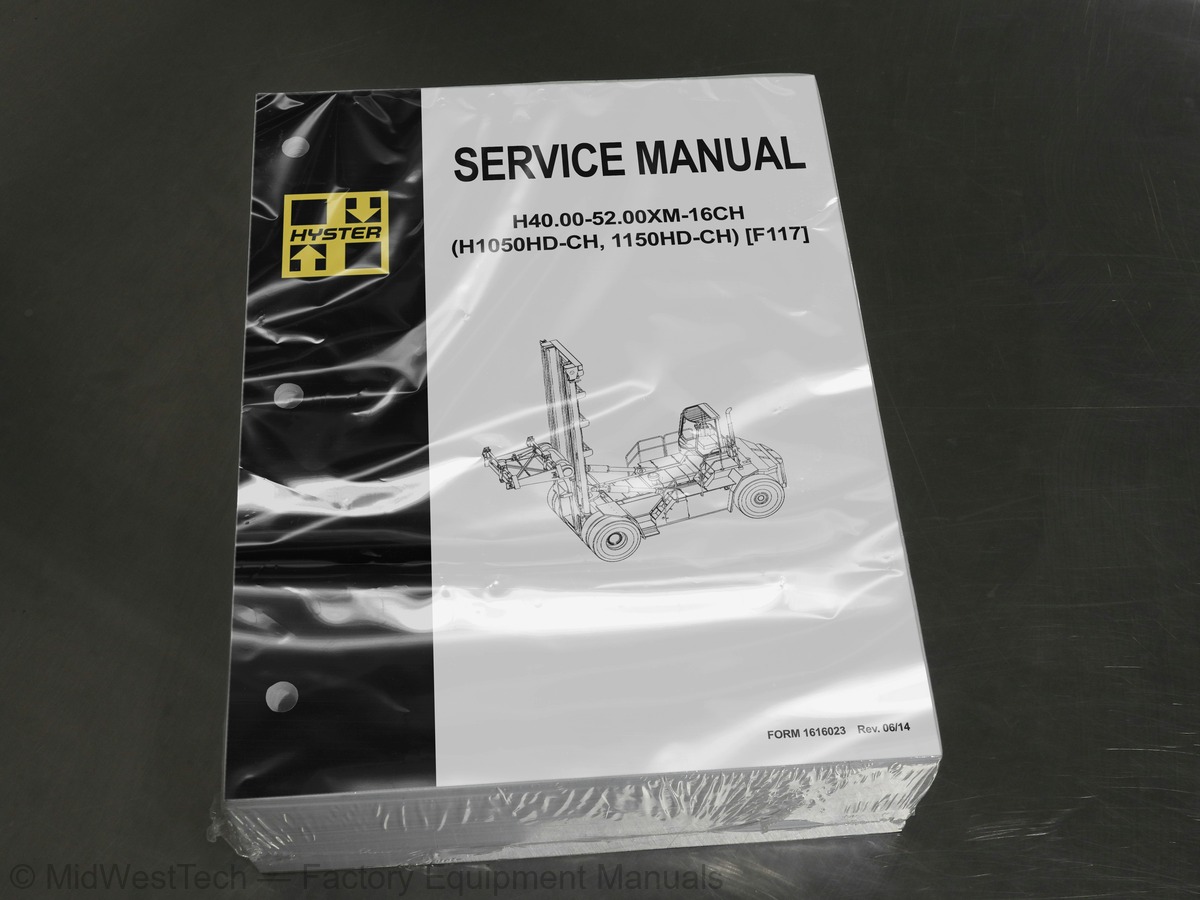
Hyster H40.00-52.00XM-16CH (H1050HD-CH, 1150HD-CH) (F117) Heavy Duty Forklift Service Manual
1,394 pages · Publication 1616023
Added to your cart. View cart
- Models
- H40.00-52.00XM-16CH (H1050HD-CH, 1150HD-CH) (F117)
- Manual type
- Service Manual
- Pages
- 1,394
- Publication
- 1616023
- Condition
- Brand new
What's inside
From the manual's own table of contents: 196 sections, 686 entries. See sample pages (PDF, 215 KB)
Differential Repair23 topics
- Remove
- Differential Carrier From Axle Housing, Remove
- Differential and Ring Gear From Differential Carrier, Remove
- Drive Pinion and Pinion Carrier From Differential Carrier, Remov
- Disassemble
- Differential and Ring Gear Assembly, Disassemble
- Drive Pinion and Pinion Carrier, Disassemble
- Clean and Inspect
- Assemble
- Pinion, Bearings, and Pinion Carrier, Assemble
- Pinion Bearings, Adjust Preload
- Triple-Lip Seal, Install
- Pinion Carrier Shim Set, Adjust Thickness (Depth of Pinion)
- Differential and Ring Gear, Assemble
- Differential Gears Rotating Torque, Check
- Differential and Ring Gear Assembly, Install
- Differential Bearings, Preload Adjust
- Ring Gear, Runout Check
- Ring Gear Backlash, Adjust
- Gear Set, Tooth Contact Pattern Check
- Thrust Screw, Install and Adjust
- Install
- Differential Assembly Into Axle Housing, Install
Operation2 topics
- Flow Control Valve
- Relief Valve
Hydraulic Gear Pump Repair2 topics
- Clean
- Inspect
Pump Output Check2 topics
- Method No. 1
- Method No. 2
Accumulator Maintenance4 topics
- Pre-Charge Check
- Pre-Charge Filling
- Repair
- Replace
Show all 196 sections
Service Brake1 topic
- B222 Only
Repair18 topics
- General
- Drive Wheels and Tires
- Brake Housing
- Spindle and Brake Cover
- Ground and Polished Parts
- Parts With Rough Finish
- Wet Disc Brake and Axle Assembly
- Face Seals
- Disc
- Parts
- Brake Housings
- Hub Oil Seals
- Spindle and Brake Cover
- Brake Housing
- Drive Wheels and Tires
- Pressure Switch
- Replace
- Accumulator
Brake Pedal Valves (Treadle Valves) Repair6 topics
- Remove
- Clean and Inspect
- Install
- Remove
- Clean and Inspect
- Install
Brake System Air Removal3 topics
- Brake Coolant
- Coolant Change Intervals
- Hydraulic Fluid
Cab Repair5 topics
- Rear Cab Assembly
- Bottom Cab Assembly
- Cab Repair
- Remove
- Install
Declutch (E117), Inching (F117), and Brake Pedals4 topics
- Brake Pedal, Adjust
- Declutch Pedal, Adjust (E117 Only)
- Inching Pedal, Adjust (F117 Only)
- Inching Pedal Sensor, Adjust (F117 Only)
Throttle Pedal Sensor Adjustment5 topics
- Cable Alignment
- Engine Side
- Pedal Housing Side
- Check
- Adjust
Window Wipers Replacement4 topics
- Window Wiper Assembly, Replace
- Front Window Wiper Motor Assembly, Replace
- Rear Window Wiper Motor Assembly, Replace
- Top Window Wiper Motor Assembly, Replace
Window Washer Motors and Pumps1 topic
- Window Wiper and Washer Operating Switches
Window Replacement4 topics
- Front Window, Replace
- Rear Window, Replace
- Top Window, Replace
- Door Window, Replace
Heater and Air Conditioning Assembly10 topics
- Heater Parts, Replace
- Heat Control Knob/Switches
- Heat Control Knob/Cable
- Adjust
- Air Control Knob/Cable
- Adjust
- Air Filter, Replace
- Air Conditioning Condenser Fan(s)
- Remove
- Install
Instruments, Switches, and Controls2 topics
- Switches
- Controls
Fuses, Relays, And Power Sources4 topics
- Fuse Panel
- Fuses
- Relays
- Power Sources
Parking Brake Caliper Repair1 topic
- Bleed Brakes
Seals Repair3 topics
- Torque Requirements
- Wear Limits
- Lining to Disc Clearance
Multiple Aligned Cooling System5 topics
- Radiator
- Radiator Cap
- Thermostat
- Water Pump
- Fan and Fan Shroud
Cooling System Checks1 topic
- Exhaust Leaks
Radiator Cleaning2 topics
- Drain
- Fill
Mast2 topics
- Lifting
- Lowering
Forks Repair1 topic
- Low-Mount Fork
Carriage Repair2 topics
- Carriage Side Blocks
- Adjust
Planetary Gear Axle Repair24 topics
- Drive Wheels and Tires
- Drive Axle
- Planetary Gear Carrier
- Ring Gear, Ring Gear Hub, and Wheel Hub
- Hub Oil Seal and Bearings
- Axle Shaft
- Spindle
- Repairing or Replacing Parts
- Welding
- Ground or Polished Parts
- Parts With Rough Finishes
- Axle Assemblies
- Drying Cleaned Parts
- Preventing Corrosion
- Parts Inspection
- Spindle
- Axle Shaft
- Hub Oil Seal and Bearings
- Ring Gear, Ring Gear Hub, and Wheel Hub
- Wheel Bearing Preload
- Planetary Gear Carrier
- Drive Axle
- Wheel Ends
- Drive Wheels and Tires
Hydraulic Tank Repair9 topics
- Small Leaks
- Large Leaks
- Steam Method
- Chemical Solution Method
- Other Methods of Preparation for Repair
- Suction Screen and Inspection Cover
- Remove
- Clean and Inspect
- Install
Fuel Tank Repair2 topics
- Remove
- Install
Hydraulic Plate11 topics
- Hydraulic Oil Supply
- Manifold, Section 1 of Hydraulic Plate
- Main Control Valve, Section 2 of Hydraulic Plate
- Description
- Operation
- Return Manifold, Section 3 of Hydraulic Plate
- Brake Manifold, Section 4 of Hydraulic Plate
- Cooling Circuit
- Service Brake
- Parking Brake
- Flow Amplifier, Section 5 of Hydraulic Plate
Manifold, Section 1 of Hydraulic Plate1 topic
- Valves and Pressure Switches
Main Control Valve, Section 2 of Hydraulic Plate6 topics
- Auxiliary Section
- Lift Section
- Lift/Tilt Section
- Auxiliary Section
- Lift Section
- Lift/Tilt Section
Torque Values2 topics
- Measurements
- Adjustments
Instrument Panel Indicators and Senders5 topics
- Instrument Panel Meters, Indicators, and LCD Display
- Connector
- Seat Switch Logic
- Central Warning Light Output
- Buzzer Output
Instrument Panel Component Replacement4 topics
- Instrument Panel
- Remove
- Light
- Replace
Sender Replacement6 topics
- Fuel Level Sender
- Pressure Sender
- Temperature Sender
- Low Coolant Sender
- Vacuum Switch
- Crankshaft Position Sensor
Warning Devices5 topics
- Description
- Operator-Controlled Air Horn
- Reverse Warning Horns/Lights
- Warning Lights
- Replace
Periodic Maintenance7 topics
- Serial Number Data
- How to Move Disabled Lift Truck
- How to Tow Lift Truck
- How to Put Lift Truck on Blocks
- How to Raise Drive Tires
- How to Raise Steering Tires
- How to Clean a Lift Truck
Maintenance Schedule1 topic
- Spreader Maintenance
Maintenance Procedures Every 8 Hours or Daily36 topics
- How to Make Checks With the Engine Stopped
- Warning and Safety Labels
- Wheels, Tires and Tire Pressure
- Wheel Nuts
- Mast, Carriage, and Attachments
- Forks
- Header Hose Assembly
- Pre-Cleaner for Air Filter
- Hydraulic Tank Breather
- Fuel, Oil, or Coolant Leaks
- Air Intake Piping and Charge Air Piping
- Drive Belt
- Engine Compartment
- Radiator Sections for Engine Coolant, Charge Air Cooler, Transmi
- Windshield Washer Fluid
- Hydraulic System Oil
- Engine Oil
- How to Make Checks With Engine Running
- Seat Belt, Seat Rails, and Steering Column
- Gauges, Lights, Horn, Fuses, and Relays
- Windows and Mirrors
- Engine and Transmission Fault Codes
- Engine Air Filter
- Coolant Level
- Main Hydraulic Return Line Filter
- Brake Return Line Filter
- Fuel Level
- Control Levers and Pedals
- Parking Brake
- Service Brakes
- Steering System
- Mast, Carriage, and Attachment
- Signals from the Spreader Control System
- Transmission
- Operator Presence System
- Transmission Oil
First Inspection After First 100 Hours of Operation5 topics
- Lift Chains
- Bearing Pretorque in Steer Wheel Hubs
- Transmission Oil Filter
- Brake Return Line Filter
- High Pressure Hydraulic Filter
Maintenance Procedures Every 250 Hours or 3 Months33 topics
- Warnings and Safety Labels
- Wheels, Tires and Tire Pressure
- Mast, Carriage, Attachment
- Hydraulic Tank Breathers
- Air Precleaner
- Fuel, Oil, and Coolant Leaks
- Engine Air Intake Piping and Charge Air Piping
- Coolant Hoses
- Drive Belts
- Engine Compartment
- Radiator sections for Engine Coolant, Charge Air Cooler, Transmi
- Oil in Steer Wheel Hubs
- Drive Axle and Differential
- Windshield Washer Fluid
- Hydraulic System Oil
- Coolant Level
- Engine Oil Level
- Fuel Filter / Water Separator
- Transmission Oil Level
- Seat Belt, Seat Rails and Steering Column
- Steering Column Latch
- Operator Presence System
- Chain Sheave Bearings
- Inner Mast Rollers
- Carriage Rollers
- Mast Pivot Pins
- Tilt Cylinder Pivot Pins
- Fork Pins and Guides
- Steering Axle Tie Rod Pins
- Drive Shaft
- Attachment
- Twist Locks
- Signals from the Spreader Control System
Maintenance Procedures Every 500 Hours or 3 Months7 topics
- Steer Axle King Pin
- Steering Axle Pivot
- Attachment Bearing Pads and Bearing Pad Tracks
- Locking Plate for Stop Cylinder
- Hangers
- Slewing Cylinders
- Fork Contact Area with Spreader Pads
Maintenance Procedures Every 500 Hours or 6 Months4 topics
- Header Hose Assembly
- Cab Air Filter
- Cooling Fan
- Engine Oil and Oil Filter
Maintenance Procedures Every 1000 Hours2 topics
- Stop Cylinders
- Extension Cylinder Supports
Maintenance Procedures Every 1000 Hours or 6 Months5 topics
- Parking and Service Brakes
- Coolant Quality
- Operator's Cab Door Hinges
- Steer Wheel Hubs Fill
- Transmission Oil and Oil Filter
Maintenance Procedures Every 2000 Hours or 1 Year10 topics
- Steer Wheel Hub Bearings
- Brake System Accumulator
- Lift System Accumulator (Optional)
- Engine Cleaning
- Engine and Transmission Mounting
- Engine Valve and Injector Adjustment
- Adjust
- Turbo Charger
- Transmission Clutch Calibration
- Inch Pedal Sensor Calibration
Maintenance Procedures every 3000 Hours or 3 Years2 topics
- Hydraulic System Oil and Hydraulic System Suction Filter
- Hydraulic Return Filters
Maintenance Procedures Every 5000 Hours2 topics
- Container Attachment (F117)
- Air Conditioning
Maintenance Procedures Every 6000 Hours or 2 Years4 topics
- Vibration Damper
- Fan Belt and Tensioner
- Fan Drive Idler Pulley
- Fan Hub
Maintenance Procedures Every 10,000 Hours or 5 Years1 topic
- High Pressure Hydraulic Oil Filter
Lift and Tilt System Leaks Check2 topics
- Lift System
- Tilt System
Pneumatic Tires and Wheels7 topics
- Remove Wheels From Lift Truck
- Remove Tire From Wheel
- Remove Tire From Five-Piece Wheel
- Install Tire on Wheel
- Install Tire on Five-Piece Wheel
- Add Air Pressure to Tires
- Install Wheels on Lift Truck
Hydraulic System Specifications13 topics
- Control Valves
- Electrical System
- Counterweight (Fabricated)
- Counterweight (Slab)
- Drive Axle
- Wheel Bearing Adjusting Nut
- Differential
- Transmission
- Torque Converter
- Steering
- Wheel Nuts
- Carriages (All)
- Attachment - 20- to 40-Foot
Description of Operation4 topics
- Hydraulic Operation
- Variable Force Solenoids
- Speed Engagement
- Cooling and Lubrication
Control System14 topics
- APC200 Controller
- Self Test
- Protection Modes
- Fault Codes
- Fault Log Mode
- Fault Identification
- Transmission Control Valve
- Hydraulic Control Valve Repair
- Pressure Check
- Pressure Specifications
- Pressure, Speed, and Temperature Sensors
- Pressure Switch
- Speed Sensor
- Temperature Sensors
Transmission Test and Calibration12 topics
- Precautions
- Stall Test
- Description
- Stall Test Procedure
- Clutch Filling Calibration
- Description
- Procedure
- Inching Calibration
- Description
- Brake and Inching Pedal Adjustment
- Inching Pedal Sensor Adjustment
- Inching Pedal Sensor Calibration
APC200 Display Information15 topics
- General Information Group
- Fault Codes
- Indication of Protection Modes
- Test Function Group
- Digital Input Test
- Analog Input Test
- Speed Sensor Test
- Output Test
- Voltage Test
- Calibration Group
- Calibration Mode
- Clutch Filling Calibration
- Heat Up Mode
- Inching Pedal Sensor Calibration
- Torque Specifications for Lubricated or Plated Screw Threads
Hydraulic System11 topics
- Hydraulic Plate
- Hydraulic Pumps
- Cab Manifold
- Oil Cooled Brakes (Service Brakes)
- Lift/Tilt Functions
- Over Lower Interrupt
- Lift Interrupt
- Accumulator Charge Disabling Solenoid (ACDS)
- Heat Exchanger System
- Steering Control System
- Brake System
Hydraulic Pump Repair7 topics
- Tandem Gear Pump
- Tri-Section Gear Pump
- Tandem Gear Pump
- Tri-Section Gear Pump
- Pump Output Check
- First Method
- Second Method
Cab Manifold2 topics
- Disassemble Valves and Pressure Switches
- Assemble Valves and Pressure Switches
Lift and Lower Circuit9 topics
- Operation
- Lift Circuit
- Lowering
- Lowering Control Valves
- Repairs
- General
- Remote Control Valve
- Lift Manifold
- Checks and Adjustments
Tilt Control Circuit7 topics
- Tilt /Lift Spool
- Relief Valves in Main Control Valve
- Relief Valves, Tilt Lock
- General
- Relief Valves, Tilt Lock, Disassemble
- Clean and Inspect
- Checks and Adjustments
Attachment Circuit Valves2 topics
- Selector Valves Auxiliary Functions
- Carriage Solenoid Valve
Other Hydraulic Components28 topics
- Description and Operation
- Relief Valves in Steering and Lift Circuits
- Reducer Valve
- Hydraulic Filters
- Suction Filters
- High Pressure Filter
- Brake Filter
- Return Line Filters
- Hydraulic Hose Repair
- Pilot Setting, Check
- Return Pressure, Check
- Main Function Relief Valve Pressure, Check
- Hydraulic Tank Breathers
- Hydraulic Pumps Output at 2100 rpm (Governed Speed)
- Relief Valves (Approximate Operating Pressures)
- Check Port Pressures
- Main Hydraulic Filters
- Tank Capacity
- Remote Control Valves
- Attachment Control Valve
- Carriage Solenoid Valve
- Lift and Lower Circuit
- Tilt Circuit
- Attachment Circuit Valves
- Other Hydraulic Components
- Accumulator Circuit
- MPa ( 725 psi) Pilot Circuit
- Park Brake Circuit
Aurora Heater and Air Conditioner25 topics
- Heater System
- General
- Dryer
- Control Systems, Sensors, and Switches
- Heater System Repair
- Heater Assembly
- Heater Assembly Parts, Replace
- Heater Core
- Evaporator Core
- Blower
- Water Valve
- Vent Door
- Push/Pull Cable, Replace
- Water Valve Cable
- Vent Door Cable
- Electric-Operated Heater Control and Fan Control
- Remove
- Install
- Cable-Operated Heater Control and Air Control
- Remove
- Install
- Air Conditioning Switch
- Remove
- Install
- Technical Detail
Aurora_AC21 topics
- Compressors - Applications, Conditions of Use and Liability
- Filling procedure for refrigerants
- Troubleshooting
- Check refrigerant level and pressure as instructed in the Technical Information sheet for the unit
- By wrong refrigerant level there is a danger of compressor malfunction
- The outcome of too much refrigerant is a oil attenuation and reflux of the refrigerant can cause damages on the valve pl
- With undercharged refrigerant the compressor will become hotwhich caused a failure. The sealing will be damaged
- Faulty shaft seals: On older compressors the shaft seal can be damaged when the unit is switched on for first time after
- Noises Mechanical faults in compressors are generally indicated by unusual noises or by unusually quiet or noisy operati
- Electrical faults A 5A fuse is used for the magnetic coupling on the compressor. The magnetic coupling can be checked by
- Technical modifications reserved
- Condenser unit, 24V
- Safety advices
- we reserve the right to make technical modifications
- 1Safety advices
- Maintenance work on the refrigeration circuit
- every six months – authorised workshop
- A contaminated condenser has a minimised condensing performance. The cleaning is carried out by blow-out or spraying (do
- every month sight checks - Operator
- Check condenser of contamination by dust, insects or parts of plants
- A contaminated condenser has a minimised condensing performance. The cleaning is carried out by blow-out or spraying (do
Inside this manual
Real pages from this service manual (1,394 pages). Open the sample pages (PDF, 214 KB)
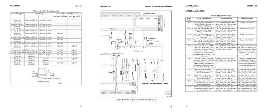
- Specifications, page 226: Table 11. Cotter Pin Dimensional Data
- Diagram, page 772: Diagrams, Schematics, or Arrangements
- Troubleshooting, page 1,129: APC200 FAULT CODES
This is a service manual
Here's how it compares to the other manual types.
Service manual
Factory repair procedures and technical information such as specifications, troubleshooting, and wiring and hydraulic diagrams, for the models and systems the manual covers. See What's inside for its topics.
Operator's manual
Safe operation, controls, maintenance schedules, lubrication points, inspections, and basic checks. Repair procedures are in the service manual.
Parts manual
Illustrated diagrams with factory part numbers for identifying components and ordering parts. Repair procedures are in the service manual.
Engine service manuals are sometimes sold separately, since certain machine models were offered with more than one engine option.
What it's used for
Factory manual for in-house farm and construction shop use. Straightforward, complete, and easy to follow. It contains the OEM information dealership service departments and parts counters use to diagnose problems, identify components, and perform maintenance or repairs correctly.
Service shops and owner/operators who repair their own equipment
Identifying correct parts and seeing how assemblies come apart and go back together
Keeping equipment running with less downtime
Factory manual, 1,394 pages
Quantity one is the manual described above.
Fast free USA shipping
Ships in 1 business day.
60-day returns
Free if the mistake is ours. A manual ordered in error must come back unopened in its shrink-wrap; you pay return shipping and a 20% restocking fee applies. Return policy
Binder not included
Manuals over about 300 pages may need a standard 3-ring binder, which you can buy locally to keep the pages organized for shop use.
Other editions and similar models
Questions about model, serial number, engine coverage or contents? Contact us before purchasing and we'll help confirm it's the right manual. Please verify the manual type, machine model, serial number range and engine coverage before purchasing: manuals ordered in error carry a 20% restocking fee (return policy).