Hyster K007 (H190HD2, H210HD2, H230HD2, H230HDS2, H250HD2, H280HD2) Heavy Duty Forklift Service Manual
1,343 pages · Publication K007
Added to your cart. View cart
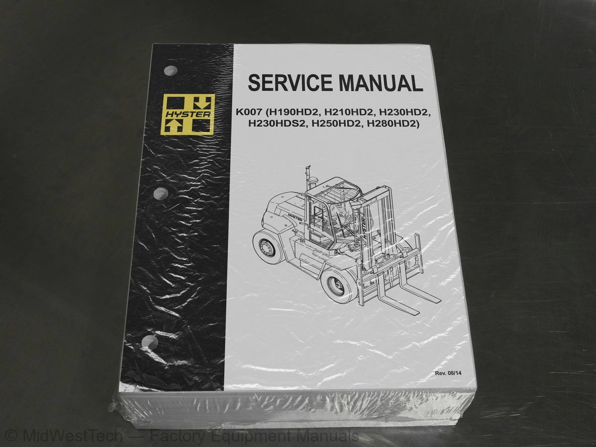
What's inside
From the manual's own table of contents: 118 sections, 436 entries. See sample pages (PDF, 460 KB)
Differential Repair23 topics
- Remove
- Differential Carrier From Axle Housing, Remove
- Differential and Ring Gear From Differential Carrier, Remove
- Drive Pinion and Pinion Carrier From Differential Carrier, Remov
- Disassemble
- Differential and Ring Gear Assembly, Disassemble
- Drive Pinion and Pinion Carrier, Disassemble
- Clean and Inspect
- Assemble
- Pinion, Bearings, and Pinion Carrier, Assemble
- Pinion Bearings, Adjust Preload
- Triple-Lip Seal, Install
- Pinion Carrier Shim Set, Adjust Thickness (Depth of Pinion)
- Differential and Ring Gear, Assemble
- Differential Gears Rotating Torque, Check
- Differential and Ring Gear Assembly, Install
- Differential Bearings, Preload Adjust
- Ring Gear, Runout Check
- Ring Gear Backlash, Adjust
- Gear Set, Tooth Contact Pattern Check
- Thrust Screw, Install and Adjust
- Install
- Differential Assembly Into Axle Housing, Install
Operation1 topic
- Identification
Disassembly4 topics
- Planetary Spider and Gearing Assembly H8.00-12.00XM (H170-280HD)
- Planetary Spider and Gearing Assembly H13.00-14.00XM (H300-330HD
- Wheel End
- Spindle and Piston Housing
Cleaning4 topics
- Clean Ground or Polished Parts
- Clean Parts With Rough Finish
- Clean Axle Assemblies
- Drying Cleaned Parts
Parts Inspection9 topics
- Tapered Roller Bearings
- Bevel Pinion and Ring Gear Sets
- Main Differential Assembly
- Axle Shafts
- Yoke
- Brakes
- Repair or Replace Parts
- Repair Welding
- Apply Silicone Gasket Material
Assembly4 topics
- Spindle and Piston Housing to Axle Housing
- Wet Disc Brakes
- Adjust Wheel Bearing Preload
- Planetary Spider Assembly
Show all 118 sections
Installation1 topic
- Fill Wet Disc Brakes With Hydraulic Fluid
Masts and Carriages2 topics
- Two-Stage Mast
- Three-Stage Mast
Forks Repair1 topic
- Inspect and Adjust
Carriage Repair3 topics
- Description
- Three Function
- Four to Six Function
Mast Repair21 topics
- Two- and Three-Stage Mast
- Remove
- Disassemble
- Clean and Inspect
- Assemble
- Install
- Three-Stage Mast (Four Cylinders)
- Remove
- Disassemble
- Clean and Inspect
- Assemble
- Install
- Fork Carriage Chains
- Adjust
- Bearing Rollers
- Description
- Lubrication
- Clearance
- Remove and Disassemble
- Assemble
- Mast Profile
Lift Cylinders Description2 topics
- Piston-Type Cylinders
- Displacement-Type Cylinders
Lift and Tilt System Leak Checks2 topics
- Lift System
- Tilt System
Mast Adjustments2 topics
- Bearing Blocks, Two-Stage Masts
- Wear Plates
Extendable Container Attachment (Elme)33 topics
- Attachment Mounting
- Attachment Functions
- Twist Locks
- Carriage
- Seated Pin
- Indicator Lights
- Twist Module
- ELME Hydraulic System
- ELME Main Direction Control Valve
- Sideshift Circuit
- Sideshift
- Extension Cylinder Control Valve
- Extend and Retract Circuit
- Twist Lock Circuit
- Stop Cylinder Circuit
- Optional Powered Pile Slope
- ELME 580 Series Valves
- Sequence Valve
- Pilot Check Valve
- Electrical System
- Printed Circuit Board
- PCB Sockets
- Cable Number
- Wire Number
- Wire Color Code
- Cable Connectors
- Sensors and Solenoids
- Indicator Lights
- Automatic Locking
- Lift Interrupt and Override
- Lift Interrupt
- Overlowering Interrupt and Override
- Second Container Detection Sensor (Model 582 Only)
Container Attachment2 topics
- Carriage and Attachment Removal
- Spreader
Wear Pads19 topics
- Wear Pads Mounted on Main Frame
- Remove
- Replace
- Wear Pads Mounted on Extension Beam
- Remove
- Replace
- Floating End Beam Wear Pads
- Upper Wear Pads
- Lower Wear Pads
- Main Frame Wear Pads at Large (Right-Hand) Extension Beam
- Main Frame Wear Pads at Small (Left-Hand) Extension Beam
- Guide for Extension Cylinder
- Large Extension Beam Internal Wear Pads
- Spreader Frame
- Upper Wear Pads
- Lower Wear Pads
- Powered Pile Slope Carriage
- Upper Wear Pads
- Lower Wear Pads
Extension Cylinder11 topics
- Clean
- Inspect
- Extension Cylinder
- Disassemble
- Clean and Inspect
- Assemble
- Remove
- Install
- Sideshift Cylinder, Powered Pile Slope Cylinder, Retract Cylinde
- Disassemble
- Assemble
Floating End Beams Repair1 topic
- Hose, Replace
Twist Lock Repair for Model 5822 topics
- Upper Twist Lock
- Lower Twist Lock
Adjustments17 topics
- Twist Lock Angle
- LOCKED/NOT LOCKED Proximity Switches
- Seated Signal
- Hydraulic Pressures
- General
- Attachment Main Relief Pressure
- Extension Relief Pressure
- Slew Relief Pressure
- Sideshift Relief Pressure
- Twist Lock Angle Adjustment
- LOCKED/NOT LOCKED Sensors Adjustment
- Model 582
- Side Clamp Open/Closed Sensor Adjustment (Model 584)
- Hook in Sensor Adjustment (Model 584)
- Seated Sensor Adjustment
- Model 582
- Overlowering Protection Sensor Adjustment (All 580 Models)
Electrical Component Checks3 topics
- Printed Circuit Boards (PCB)
- Solenoids
- Proximity Switches
Basic Principles of Flow Control Systems11 topics
- Orifice (Fixed/Variable)
- Basic Principle
- Pressure Compensated Flow Control Valve
- Basic Principle
- Pressure Compensated Flow Control Valve Functional Description
- Priority Valve
- Basic Principle
- Priority Valve Functional Description
- Load Sense (LS)
- Basic Principle
- Load Sense Functional Description
Basic Principles of Pressure Control Systems15 topics
- Direct Acting Relief Valves
- Basic Principle
- Direct Acting Relief Valve Functional Description
- Two-Stage Relief Valve (Pilot-Operated Relief Valve)
- Basic Principle
- Two-Stage Relief Valve (Pilot Operated Relief Valve) Functional
- Unloading Valve (Accumulator Charging Valve)
- Basic Principle
- Unloading Valve (Accumulator Charging Valve) Functional Descript
- Counterbalance Valve
- Basic Principle
- Counterbalance Valve Functional Description
- Pressure Reducer Valve
- Basic Principle
- Pressure Reducer Valve Functional Description
Brake Pressure System24 topics
- Main System
- Introduction
- Description
- Hydraulic Oil Flow Path
- Fundamentals
- Description
- Operation
- Component Validation for Correct Operation
- Brake Control Manifold
- Description
- Orifice (F)
- Unloading Valve
- Screen
- Check Valve
- Pressure Reducer Valve
- Park Brake Selector Valve
- Brake Accumulator
- Fundamentals
- Operation
- Component Validation for Correct Operation
- Brake Treadle Valve
- Fundamentals
- Description
- Operation
Wet Disc Brake Cooling System24 topics
- Introduction
- Description
- Hydraulic Oil Flow Path
- Gear Pump
- Fundamentals
- Operation
- Brake Cooling Valve
- Description
- Operation
- Thermostatic Bypass Valve
- Brake Flow Distribution Manifold
- Fundamentals
- Operation
- Component Validation for Correct Operation
- Hydraulic Oil Cooler Core
- Fundamentals
- Operation
- Brake Return Line Filter ( J007 & H019 Only)
- Operation
- Cooling System Air Brakes
- Main System
- Description
- Hydraulic Oil Flow Path
- Component Explanation
Accumulator2 topics
- Repair
- Pre-Charge Filling
Parking Brake11 topics
- Parking Brake Caliper
- Remove
- Disassemble
- Clean and Inspect
- Assemble
- Install
- Parking Brake Caliper Pads
- Remove
- Install
- Parking Brake Bleed
- Parking Brake Emergency Release
Brake Flow Distribution Manifold2 topics
- Pressure Relief Valve
- Disassemble
Brake Control Manifold7 topics
- Orifices F and G
- Orifice H
- Unloading Valve (B)
- Screen
- Check Valve (E)
- Pressure Reducer Valve (C)
- Park Brake Selector Valve (A)
Brake Cooling Valve6 topics
- Filter Restriction Indicator (Optional)
- Remove
- Install
- Filter
- Remove
- Install
Brake Return Line Filter ( J007 & H019 Only)5 topics
- Brake Return Line Filter Assembly
- Remove
- Install
- Remove
- Install
Checks and Adjustments10 topics
- Hydraulic Pressure Checks Preparation
- Park Brake Selector Valve Check
- Park Brake Selector Valve Coil Check
- Accumulator Pre-Charge Check
- Parking Brake Adjustment
- Condition Check, Shuttle Valve L in the Main Control Valve
- Condition Check, Shuttle Valve N in the Main Control Valve
- Condition Check, Priority Valve on the Main Control Valve
- Pressure Check, Port MLS1
- Hydraulic Hose Torque Specifications
Air Cleaner6 topics
- Air Cleaner Assembly, Tier 3/Stage III A, J019/K007
- Remove
- Install
- Air Cleaner Assembly, Tier 4i/Stage III B, J019/K007
- Remove
- Install
Exhaust System6 topics
- Exhaust Assembly, Tier 3/Stage III A, J019/K007
- Remove
- Install
- Exhaust Assembly, Tier 4i/Stage III B, J019/K007
- Remove
- Install
Hydraulic Tank2 topics
- Additional Preparations for Repair
- Preparations for use After Repair
Fuel Tank6 topics
- Raising and Lowering Cab
- Raise Cab
- Lower Cab
- Cab Repair
- Remove
- Install
Counterweight1 topic
- General
Torque Specifications, Cummins Diesel1 topic
- Lubrication System
Torque Specifications, General12 topics
- Transmission ZF
- Driveline and Axle
- Counterweight
- Differential
- Brakes - Wet
- Steering
- Wheel Nuts
- Hydraulic System
- Mast
- Carriage
- Tilt Cylinders
- Wiper Arms, Front
Inside this manual
Real pages from this service manual (1,343 pages). Open the sample pages (PDF, 460 KB)

- Troubleshooting, page 176: Table 5. Error Code Descriptions (Continued)
- Diagram, page 316: Schematics
- Specifications, page 1,256: Engine Specifications
- Color page, page 859: Figure 16. Hydraulic Component Location, Wet Brakes, Dual Pump Configuration
- Color page, page 1,161: Diagrams, Schematics, or Arrangements
- Foldout diagram (color), page 1,152: Figure 3. Hydraulic Schematic, Wet Brakes - Double Pump Option
This is a service manual
Here's how it compares to the other manual types.
Service manual
Factory repair procedures and technical information such as specifications, troubleshooting, and wiring and hydraulic diagrams, for the models and systems the manual covers. See What's inside for its topics.
Operator's manual
Safe operation, controls, maintenance schedules, lubrication points, inspections, and basic checks. Repair procedures are in the service manual.
Parts manual
Illustrated diagrams with factory part numbers for identifying components and ordering parts. Repair procedures are in the service manual.
Engine service manuals are sometimes sold separately, since certain machine models were offered with more than one engine option.
What it's used for
Factory manual for in-house farm and construction shop use. Straightforward, complete, and easy to follow. It contains the OEM information dealership service departments and parts counters use to diagnose problems, identify components, and perform maintenance or repairs correctly.
Service shops and owner/operators who repair their own equipment
Identifying correct parts and seeing how assemblies come apart and go back together
Keeping equipment running with less downtime
Factory manual, 1,343 pages
Quantity one is the manual described above.
Fast free USA shipping
Ships in 1 business day.
60-day returns
Free if the mistake is ours. A manual ordered in error must come back unopened in its shrink-wrap; you pay return shipping and a 20% restocking fee applies. Return policy
Binder not included
Manuals over about 300 pages may need a standard 3-ring binder, which you can buy locally to keep the pages organized for shop use.
Other editions and similar models
Questions about model, serial number, engine coverage or contents? Contact us before purchasing and we'll help confirm it's the right manual. Please verify the manual type, machine model, serial number range and engine coverage before purchasing: manuals ordered in error carry a 20% restocking fee (return policy).