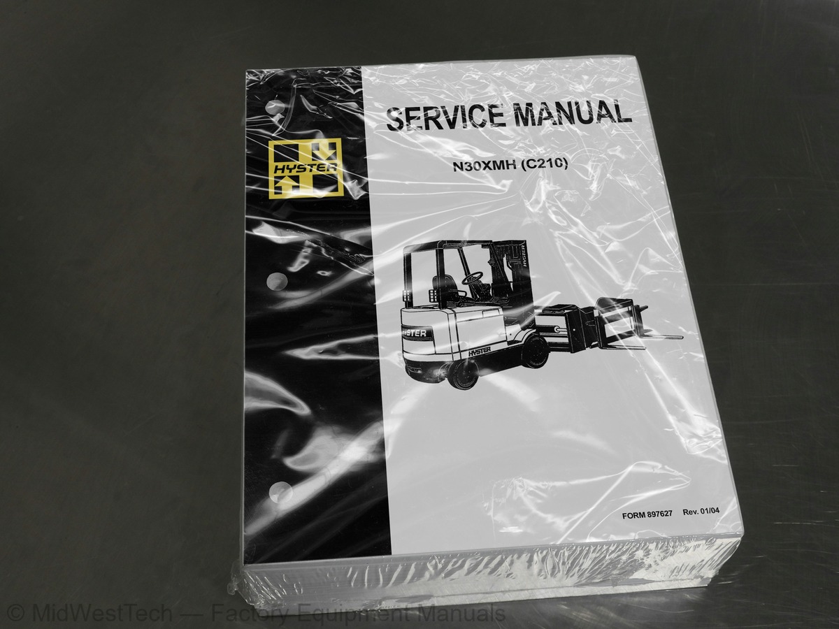
Hyster N30XMH (C210) Forklift Service Manual
910 pages · Publication 897627
Added to your cart. View cart
- Models
- N30XMH (C210)
- Manual type
- Service Manual
- Pages
- 910
- Publication
- 897627
- Condition
- Brand new
What's inside
From the manual's own table of contents: 159 sections, 554 entries. See sample pages (PDF, 280 KB)
Drive Axle, Speed Reducer, and Differential Repair9 topics
- Drive Axle, Remove
- Drive Axle, Disassemble
- Speed Reducer and Differential, Disassemble
- Clean
- Inspect
- Assemble
- Speed Reducer and Differential, Assemble
- Drive Axle, Assemble
- Drive Axle Assembly, Install
Torque Specifications13 topics
- Wheel Nuts
- Axle Shaft Capscrews
- Axle Hangers to Frame
- Back Plate to Axle Mount Capscrews
- Wheel Cylinder Capscrews
- Ring Gear to Differential Case
- Differential Case Halves
- Bearing Cap Capscrews
- Retainer Capscrews
- Axle Housing to Differential Housing
- Pinion Nut
- Speed Reducer Housing to Differential Housing
- Traction Motor to Transmission
Brush and Commutator Inspection4 topics
- Hydraulic Pump Motor and Traction Motor
- Steering Pump Motor
- Normal Commutator Surface
- Commutator Problems
Motors Repair5 topics
- Disassemble
- Traction Motor and Hydraulic Pump Motor
- Steering Pump Motor
- Traction Motor and Hydraulic Pump Motor
- Steering Pump Motor
Tests for Damaged Field and Armature7 topics
- Test for an Open Circuit in Armature
- Test for Short Circuit in One Armature Winding
- Test for Short Circuit to Armature Shaft
- Test for Open Circuit in Field Coil
- Test for Short Circuit in Field Coil
- Test for Short Circuit between Field and Motor Case
- Brush Holder Test
Two-Stage Mast2 topics
- Description
- Operation
Show all 159 sections
Lift Cylinders1 topic
- Lowering Control Valve
Load Backrest Extension, Carriage, Load Rollers, Side Rollers, a6 topics
- Load Backrest Extension, Remove and Install
- Carriage Assembly, Remove and Install
- Carriage Load Rollers, Remove and Install
- Side Rollers, Disassemble and Assemble
- Fork, Replace
- Forks - Hook Type
Two-Stage Mast Assembly15 topics
- Remove
- Clean and Inspect
- Lift Cylinders, Remove and Install Dual-Lift Cylinders
- Lift Cylinder, Remove and Install Single-Lift Cylinders
- Remove
- Install
- Inner Mast Assembly, Remove and Install
- Hoses, Replace
- Hose and Cable Sheaves, Replace
- Two-Stage Lift Chains
- Remove and Install
- Clean and Inspect
- Two-Stage Chain Sheave, Remove and Install
- Load Rollers and Wear Plugs, Remove and Install
- Two-Stage Mast Assembly, Install
Three-Stage Mast Assembly16 topics
- Three-Stage Mast Assembly, Remove
- N30XHM Only
- Free-Lift Cylinder, Remove and Install
- Main Cylinders (Standard), Remove and Install
- Main Cylinders (N30XMH), Remove and Install
- Inner and Intermediate Mast Assemblies, Remove and Install
- Free-Lift Hose Sheave
- Carriage Sheaves
- Three-Stage Lift Chains, Remove and Install
- General
- Free-Lift Chains
- Main-Lift Chains
- Three-Stage Chain Sheaves, Disassemble and Assemble
- Free-Lift Chain Sheaves
- Main-Lift Chain Sheaves
- Three-Stage Mast Assemble, Install
Lift Chains Check2 topics
- General
- Lubrication
Mast Adjustments6 topics
- Adjust Wear Plugs - Mast
- Adjust Free-Lift Chain (Three-Stage Only)
- Adjust Main-Lift Chains
- Two-Stage
- Three-Stage
- Adjust Wear Strips
Carriage Adjustments3 topics
- Adjust Wear Plug - Carriage
- Adjust Side Rollers - Carriage
- Adjust Thrust Rollers - Carriage
Steering Wheel and Column Assembly Repair2 topics
- Assembly Components, Remove
- Assembly Components, Install
Power Steering Motor and Pump7 topics
- Remove and Disassemble, Models J2.00-3.20XM (J40-60XM, J40-60XM
- Remove and Disassemble, Models A1.00-1.50XL (A20-30XL)
- Remove and Disassemble, Models E1.50-2.00XMS (E25-40XMS, E25-40X
- Assemble and Install - All models with a vertical mount except J
- Assemble and Install, Models E1.50-2.00XMS (E25-40XMS, E25-40XM
- Power Steering Pump, Repair
- Seal, Replace
Hydraulic Steering Motor6 topics
- Hydraulic Steering Motor Repairs
- Remove
- Disassemble
- Clean and Inspect
- Assemble
- Install
Operation3 topics
- Steering Column Assembly, Remove
- Steering Control Unit
- Steering Column Assembly, Install
Instrument Cluster7 topics
- Display Panels on Steering Column, Internal Combustion
- Display Panels on Steering Column, Electric Lift Trucks
- Standard Display Panel
- Enhanced Display Panel
- Curtis 1215 Display Panel
- Description and Features
- Operation
Cluster-Type Display Panel (Internal Combustion) Replacement2 topics
- Remove and Disassemble
- Assemble and Install
Cluster Display Panel (Electric Lift Truck) Replacement7 topics
- Display Panel Assembly, Replace
- LED Indicators
- Battery Indicators
- Digital Display (Enhanced Display Panel Only)
- Status Code or Performance Level Switches and LED indicators (En
- Standard Display Panel Parts, Replace
- Enhanced Display Panel Parts, Replace
Curtis 1215 Display Panel Replacement1 topic
- Install
EV-100ZX™ SCR Motor Controller1 topic
- Model Number Data For EV-100ZX Controller
Register Parameters1 topic
- Function Numbers
Handset7 topics
- How to Check and Adjust Registers
- How to Scroll through Fault Codes and Clear Them
- Checks and Adjustments on Workbench
- When Handset Is Connected to Control Card Installed In Lift Truc
- Function Numbers 1 through 15
- Function Numbers 16 through 30
- Function Numbers 48 through 62
Control Cards68 topics
- Function Number Descriptions
- Traction Control Cards (Label Letters - ZH and ZY)
- Function Number 1 STORED STATUS CODE
- Function Number 2 CREEP SPEED
- Function Number 3 CONTROLLED ACCELERATION AND 1A TIME
- Function Number 4 CURRENT LIMIT
- Function Number 5 PLUGGING DISTANCE (CURRENT)
- Function Number 6 1A DROP OUT CURRENT
- Function Number 7 FIELD WEAKENING PICK UP
- Function Number 8 FIELD WEAKENING DROP OUT
- Function Number 9 REGENERATIVE BRAKING CURRENT LIMIT
- Function Number 10 REGENERATIVE BRAKING START
- Function Number 13 SPEED LIMIT 3 (SL3)
- Function Number 14 INTERNAL RESISTANCE COMPENSATION
- Function Number 15 BATTERY VOLTS
- Function Numbers GREATER THAN 15
- Function Number 16 PEDAL POSITION PLUG
- Function Number 17 CARD TYPE SELECTION
- Function Number 18 STEERING PUMP TIME DELAY
- Function Number 19 MAINTENANCE ALERT (Tens/Units)
- Function Number 20 MAINTENANCE ALERT (Thousands/Hundreds)
- Function Number 21 MAINTENANCE SPEED LIMIT
- Function Numbers 22 Through 28 TEMPORARY DATA REGISTERS
- Function Number 29 HOURMETER (Tens/Units)
- Function Number 30 HOURMETER (Thousands/Hundreds)
- Function Number 48 Through 62 SET LIFT TRUCK PERFORMANCE
- Function Number 48 CONTROLLED ACCELERATION AND 1A TIME
- Function Number 49 FIELD WEAKENING PICK UP
- Function Number 50 SPEED LIMIT 1
- Function Number 52 CONTROLLED ACCELERATION AND 1A TIME
- Function Number 53 FIELD WEAKENING PICK UP
- Function Number 54 SPEED LIMIT 1
- Function Number 56 CONTROLLED ACCELERATION AND 1A TIME
- Function Number 57 FIELD WEAKENING PICK UP
- Function Number 58 SPEED LIMIT 1
- Function Number 60 CONTROLLED ACCELERATION AND 1A TIME
- Function Number 61 FIELD WEAKENING PICK UP
- Pump Control Card (Label Letter ZP)
- Function Number 1 STORED STATUS CODE
- Function Number 2 INTERNAL RESISTANCE COMPENSATION START
- Function Number 3 CONTROLLED ACCELERATION
- Function Number 4 CURRENT LIMIT
- Function Number 7 CONTROLLED ACCELERATION COMPENSATION
- Function Number 11 SPEED LIMIT 1 (SL1) (Slow Speed) - Tilt and S
- Function Number 12 SPEED LIMIT 2 (SL2) (Medium Speed) - Slow Lif
- Function Number 13 SPEED LIMIT 3 (SL3)
- Function Number 14 SPEED LIMIT 4 (SL4) Fast Lift
- Function Numbers Greater Than 15
- Function Number 16 INTERNAL RESISTANCE COMPENSATION
- Function Number 17 CARD TYPE SELECTION
- Function Numbers 18 through 28 TEMPORARY DATA REGISTERS
- Function Number 29 HOURMETER (Tens/Units)
- Function Number 30 HOURMETER (Thousands/Hundreds)
- Function Number 48 CONTROLLED ACCELERATION
- Function Number 49 SPEED LIMIT 2
- Function Number 50 SPEED LIMIT 3
- Function Number 52 CONTROLLED ACCELERATION
- Function Number 53 SPEED LIMIT 2
- Function Number 54 SPEED LIMIT 3
- Function Number 56 CONTROLLED ACCELERATION
- Function Number 57 SPEED LIMIT 2
- Function Number 58 SPEED LIMIT 3
- Function Number 60 CONTROLLED ACCELERATION
- Function Number 61 SPEED LIMIT 2
- Function Number 62 SPEED LIMIT 3
- Register Parameters
- Status Codes
- Register Maps
EV-100ZX SCR Motor Controller Repair20 topics
- Fuses
- SCR, Check
- SCR Assembly
- Thermal Protector
- SCR 1 Assembly, Replace
- OFF Circuit for SCR 1
- Reactor Assembly, Check
- Suppressors for SCR 2 and SCR 5, Check
- SCR 2 and SCR 5, Check
- SCR 2 and SCR 5, Replace
- Capacitor C1, Check
- Diodes D3 and D4
- Diodes D3 and D4, Check
- Diodes D3 and D4, Replace
- Motor Current Sensor
- Contactors
- Contactor, Repair
- Control Card
- Control Card Plugs
- Brush Wear Indicators
Theory of Operation25 topics
- Electronic Speed Controls
- Silicon Controlled Rectifier (SCR)
- Motor Circuit That Operates With Pulses
- Traction Circuit
- Hydraulic Pump Motor
- SCR 1 OFF Circuit
- Induction Current from Motor
- Control Cards
- Pulse Monitor Trip (PMT) (Traction Circuit Only)
- SRO Circuit (Traction Circuit Only)
- Sequence of Operation
- Control Card Adjustments (Traction Circuit)
- Accelerator Control
- SCR Control (Hydraulic Pump Motor)
- Circuit Protection
- Traction Circuit Fuse
- Current Limit
- Thermal Protection
- Suppressors
- Truck Management Module (TMM1)
- Display Panels
- Display Panel
- Basic Display
- Performance Display
- Brush Wear Indicators
Frame4 topics
- Main Frame
- Other Frame Weldments
- Battery Restraint/Hood Frame and Plate for Optional Seat Brake
- Overhead Guard
Hydraulic Tank Repair5 topics
- Small Leaks, Repair
- Large Leaks, Repair
- Steam Method
- Chemical Solution
- Additional Preparations for Repair
Hydraulic System6 topics
- Hydraulic Gear Pump
- Rotator Actuator Valve
- Steering Pump
- Steam Method
- Chemical Solution Method
- Additional Methods for Tank Repair
Hydraulic Pump Repair2 topics
- Pump Seal, Replace and Pump Assemble
- Assemble Pump on Motor
Steering Pump Repair1 topic
- Pump, Assemble and Install
Rotary Actuator Valve Repair1 topic
- Disassemble, Clean, and Inspect
Specifications5 topics
- Relief Valve Pressures*
- Hydraulic Tank Capacity (dipstick full mark)
- Hydraulic Pump Capacities
- Steering
- Steering Housing and Steering Control Unit
Electrical System24 topics
- ZX Series Display Panels
- Display Panel
- Basic Display Panels
- Performance Display
- Brush Wear Indicators
- SEM Display Panels - Features
- Descriptions of Common Features
- Additional Features of Premium Display Panel
- Descriptions of Additional Features
- SEM Display Panel Indicators
- All Indicator Symbols
- Hourmeter Indicator Symbol
- Wrench Indicator Symbol
- Battery Indicator Symbol
- Battery State-of-Charge (BDI)
- Brake Fluid Too Low Symbol
- Parking Brake Symbol
- Fasten Seat Belt Symbol
- LCD Screen (Standard Display Panel)
- Additional Components of Premium Display Panel
- Alpha Numerical Screen
- STAR Push Button
- Push Buttons ##1 Through ##5 - SEM
- Other Control Components
Display Panel Components Replacement8 topics
- ZX Panel Replacement
- Display Panel Assembly
- Key Switch, Replace
- Indicator LEDs
- Digital Display (Performance Display Panel Only)
- Status Code or Performance Level Switches and Indicator LEDs (Pe
- Basic Display Panel, Replace Parts
- Performance Display Panel, Replace Parts
Control Components Replacement25 topics
- Start Switch, Replace
- Brake Light Switch, Replace
- Seat Switch, Replace
- External Seat Switch, Adjust
- Switch for Optional Seat Brake, Replace
- Parking Brake Switch, Replace
- Direction Switches (MONOTROL Pedal), Replace
- Direction Control Switches (Steering Column), Replace
- Direction Control Switches, E70-120XL 3 (Steering Column)
- Brake Fluid Switch, Replace
- Brush Wear and Overtemperature Sensors
- Rocker Switches for Lights
- Accelerator Position Sensor, Replace
- On-Demand Steering Components
- Lights, Converter, Relay, and Reverse Alarm
- Brake, Tail, and Reverse Light Assembly, Replace
- Flashing Light Assembly, Replace
- Front, Rear Driving Light, or Spot Light Assemblies, Replace
- Operator Compartment Light Assembly, Replace
- Converter, Replace
- Relay, Replace
- Reverse Alarm, Replace
- Horn and Horn Button
- Horn Switch and Cover
- Hydraulic Pump Switches
Start Switch Adjustment2 topics
- Accelerator Potentiometer and Start Switch E70-120XL, E70-120XL
- Direction Switches (MONOTROL)
Direction Switches Check2 topics
- Monotrol Pedal
- Steering Column
Mast Speeds7 topics
- E45-65XM Mast Speeds (36 or 48 Volt) Americas
- J40-65XM Mast Speeds (36 or 48 Volt) Americas
- Frame
- Drive Axle, Speed Reducer, and Differential E.200-3.20XM (E45-65
- Drive Axle, Speed Reducer, and Differential J2.00-3.20XM (J40-65
- Masts
- Seat Brake
Description and Operation3 topics
- Service Brakes
- Master Cylinder
- Parking Brake
Service Brakes Repair1 topic
- Adjust
Seat Brake Assembly3 topics
- Seat Brake, Adjust - Lift Truck Models E2.00-3.20XM (E45-65XM, E
- Brake Switch, Adjust - Lift Truck Models E2.00-3.20XM (E45-65XM
- Electric Seat Brake, Adjust
Battery Ratings1 topic
- Kilowatt-Hours
Battery Maintenance16 topics
- Safety Procedures
- Maintenance Records
- New Battery
- Cleaning Battery
- Adding Water to Battery
- Hydrometer
- Battery Temperature
- Charging Battery
- Types of Battery Charges
- Methods of Charging
- Troubleshooting Charger
- Knowing When Battery Is Fully Charged
- Where to Charge Batteries
- Equipment Needed
- Battery Connectors
- Battery Care
Metric and Inch (SAE) Fasteners6 topics
- Threaded Fasteners
- Nomenclature, Threads
- Strength Identification
- Cotter (Split) Pins
- Fastener Torque Tables
- Conversion Table
Spindles, Bearings, and Tie Rods Repair3 topics
- Steering Control Unit, Disassemble
- Steering Control Unit, Clean
- Steering Control Unit, Assemble
Computer System2 topics
- Connect a PC to a Control Card
- Installation
HYTECH™ Windows Software Program18 topics
- How to Start the Program
- DEMO Mode
- Selecting the Communications Port
- Verification of Controller and Lift Truck
- Select Lift Truck Series
- Controller Card Register Parameter List
- How to Change a Parameter
- How to Save a Changed Parameter File
- How to Load a Saved Parameter File
- How to Show and Remove Saved Parameter Files
- How to Return to Factory Default Settings
- How to Save Changes to Control Card
- How to View Status Codes
- Saving Status Codes
- How to Show and Remove Saved Status Code Files
- Closing and Clearing Status Code List
- How to View Saved Register Data and Saved Status Data
- How to Save Register Data and Status Code Data In and
GE Sentry™ Software Program4 topics
- How to Start GE SENTRY Program
- How to Reset MIN and MAX Display
- Graphing Mode
- How to Exit GE SENTRY Program
Inside this manual
Real pages from this service manual (910 pages). Open the sample pages (PDF, 280 KB)
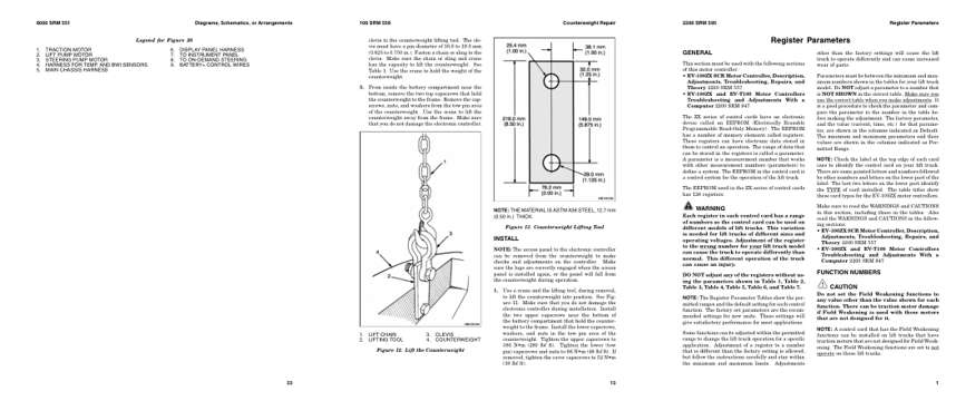
- Diagram, page 277: Diagrams, Schematics, or Arrangements
- Specifications, page 487: Counterweight Repair
- Troubleshooting, page 767: Register Parameters
This is a service manual
Here's how it compares to the other manual types.
Service manual
Factory repair procedures and technical information such as specifications, troubleshooting, and wiring and hydraulic diagrams, for the models and systems the manual covers. See What's inside for its topics.
Operator's manual
Safe operation, controls, maintenance schedules, lubrication points, inspections, and basic checks. Repair procedures are in the service manual.
Parts manual
Illustrated diagrams with factory part numbers for identifying components and ordering parts. Repair procedures are in the service manual.
Engine service manuals are sometimes sold separately, since certain machine models were offered with more than one engine option.
What it's used for
Factory manual for in-house farm and construction shop use. Straightforward, complete, and easy to follow. It contains the OEM information dealership service departments and parts counters use to diagnose problems, identify components, and perform maintenance or repairs correctly.
Service shops and owner/operators who repair their own equipment
Identifying correct parts and seeing how assemblies come apart and go back together
Keeping equipment running with less downtime
Factory manual, 910 pages
Quantity one is the manual described above.
Fast free USA shipping
Ships in 1 business day.
60-day returns
Free if the mistake is ours. A manual ordered in error must come back unopened in its shrink-wrap; you pay return shipping and a 20% restocking fee applies. Return policy
Binder not included
Manuals over about 300 pages may need a standard 3-ring binder, which you can buy locally to keep the pages organized for shop use.
Other editions and similar models
Questions about model, serial number, engine coverage or contents? Contact us before purchasing and we'll help confirm it's the right manual. Please verify the manual type, machine model, serial number range and engine coverage before purchasing: manuals ordered in error carry a 20% restocking fee (return policy).