JCB 2CX, 2CXU, 210S, 210SU Backhoe Loader Service Manual
414 pages · Publication 9803-7130
Added to your cart. View cart
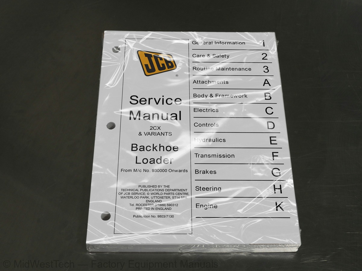
What's inside
From the manual's own table of contents: 12 sections, 271 entries. See sample pages (PDF, 420 KB)
Section 1: General Information8 topics
- Machine Identification Plate
- Typical Machine Identification Number
- Typical Engine Idenitification Number
- Unit Identification
- Torque settings
- Service Tools Numerical List
- Service Tools
- Sealing and Retaining Compounds
Section 2: Care and Safety4 topics
- Safety Notices
- General Safety
- Operating Safety
- Maintenance Safety
Section 3: Routine Maintenance83 topics
- Service Requirements
- Introduction
- Maintenance
- Owner/Operator Support
- Service/Maintenance Agreements
- Lifting Regulations - Inspections and Tests
- Lubricants - Health and Safety
- Service Schedules
- Loader Arm Safety Strut
- Installing
- Removing
- Checking for Damage
- Cleaning the Machine
- Checking the Seat Belt Condition and Security
- Checking the Rops/Fops Structure
- Checking the Fire Extinguisher
- Engine Panels
- Removing and Fitting a Side Panel
- Opening and Closing the Bonnet
- Grease (Daily)
- Loader Arms - Standard
- Loader Arms - High Specification
- Backhoe
- 6-in-1 Clamshovel (if fitted)
- Backhoe Quick-Hitch (Mechanical)
- Backhoe Quick-Hitch (Hydraulic)
- Greasing
- Axles
- Propshafts
- Airmaster Driveshaft
- Stabiliser Legs
- Extending Dipper
- Lubrication
- Tyres and Wheels
- Tyre Inflation
- Checking the Roadwheel Tightness
- Engine Air Filter
- Cleaning the Pre-Cleaner
- Changing the Elements
- Engine Oil and Filter
- Checking the Oil Level
- Changing the Oil and Filter
- Engine Cooling System
- Adjusting the Fan Belt
- Checking the Coolant Level
- Changing the Coolant
- Fuel System
- Types of Fuel, etc
- Filling the Tank
- Draining the Filter
- Changing the Filter Element
- Draining the Sediment Bowl
- Bleed the System
- Syncro Shuttle Transmission
- Checking the Oil Level
- Changing the Oil and Filter
- Brakes
- Parking Brake Adjustment
- Checking the Foot Brake Fluid Level
- Axles
- Checking the Differential Oil Level
- Changing the Differential Oil
- Checking the Hub Oil Levels
- Changing the Hub Oil
- Hydraulic System
- Checking the Fluid Level
- Changing the Filter Element
- Electrical System
- Fuses
- Relays
- Link Box Fuses
- Bulbs
- Battery
- Warning Symbols
- First Aid - Electrolyte
- Checking the Electrolyte Level
- Cab Heater
- Changing the Recirculation Filter
- Windscreen Washer
- Stabiliser Legs
- Wear Pads/Wear Pad Adjustment
- Align Road Wheels
- Fluids, Lubricants, Capacities and Specifications
Section A: Attachments19 topics
- Hydraulic Tool Circuit (H.T.C.)
- Schematic Hydraulic Circuit
- Circuit Description
- Flow Diverter Valve
- Flow Testing and Pressure Testing
- Airmaster Compressor
- Care and Safety
- Unit Identification
- Safety Decals
- Routine Maintenance
- Technical Data
- Basic Operation
- Descriptions
- Fault Finding
- Commissioning the Compressor
- Air/Oil Separator
- Pressure Regulator
- Suction Unloader
- Compressor Unit: Dismantling and Assembly
Section B: Body and Frame Work16 topics
- Basic Operation
- Air Conditioning
- Fault Finding
- Air Conditioning
- General Fault Indications
- Wiring Continuity Checks
- Service Procedures
- Air Conditioning
- Glazing/Direct Glazing
- Cab ROPS/FOPS Structure - Checks
- Stabiliser Leg - Wear Pad Adjustment
- Air Conditioning
- Blower Motor
- Thermostat
- Compressor Clutch Relay
- Stabiliser Leg - Removal and Replacement
Section C: Electrics14 topics
- Technical Data
- System Type/Bulbs
- Fuses/Relays
- Fuse Link Box/Fuse Links
- Basic System Operation
- Circuit Schematics
- Battery
- Alternator
- Starter Motor
- Wiring Harness
- Alternator
- Removal and Replacement
- Starter Motor
- Removal and Replacement
Section D: Controls5 topics
- Steering Column
- Removal and Replacement
- Dismantling and Assembly
- Loader Control Knob
- Dismantling and Assembly
Section E: Hydraulics38 topics
- System Type
- Smooth Ride System
- Component Location
- Neutral Circuit Description
- Introduction to Hydraulic Symobols
- Hydraulic Circuit Schematics
- Circuit Descriptions
- Loader Valve
- Main Relief Valve (MRV) Operation
- Excavator Valve
- Pilot-Operated Pressure Relief Valve Operation
- Ram Operation and End Damping
- Smooth Ride System
- Hydraulic System
- Smooth Ride System
- Hydraulic Contamination
- Flow and Pressure Testing
- Pressure Testing
- Quick Release Couplings
- Smooth Ride System
- Main Pump
- Removal and Replacement
- Dismantling and Assembly
- Auxiliary Pump
- Removal and Replacement
- Dismantling and Assembly
- Loader Valve
- Removal and Replacement
- Dismantling and Assembly
- Excavator Valve
- Removal and Replacement
- Dismantling and Assembly
- Hydraulic Rams
- Dismantling and Assembly - Typical Ram
- JCB Sealing Procedure
- Smooth Ride System
- Accumulator Removal and Replacement
- Accumulator Dismantling and Assembly
Section F: Transmission37 topics
- Axles
- Synchro Shuttle Gear Box
- Tyres
- Front and Rear Axles/Synchro Shuttle
- Torque Converters
- Synchro Shuttle Gearbox
- Systems Description
- Synchro Shuttle Gearbox
- Front and Rear Axle
- Brakes
- Synchro Shuttle Gearbox
- Solenoid Valve
- Torque Converter Stall Test
- Propshafts
- Removing and Replacing
- Front Axle
- Removing and Replacing
- Drive Head Maxtrac
- Pinion Depth Setting
- Collapsible Spacer Assembly
- Crownwheel and Pinion Meshing
- Drive Head Limited Slip Differential
- Axle and Hub Driveshaft
- Rear Axle
- Removal and Replacement
- Drive Head Maxtrac
- Limited Slip Differential
- Axle Hub and Driveshaft
- Brakes
- Synchro Shuttle Gearbox
- Removal and Replacement
- Dismantling and Assembly
- Reverser Unit
- Power Take Off Clutch
- Piston Ring Seals - Fitting Procedure
- Torque Converter
- Removal and Replacement
Section G: Brakes15 topics
- System Type
- Compensating Master Cylinder
- Brake System
- Service Brakes
- Parking Brake
- Compensating Master Cylinder
- Removal and Replacement
- Dismantling and Assembly
- Service Brakes
- Dismantling and Assmebly
- Bleeding
- Parking Brake
- Torque Figures
- Calliper Removal and Replacement
- Calliper Dismantling and Assembly
Section H: Steering20 topics
- System Type
- Steer System Schematics
- Hydraulic Operation
- Circuit Description
- Steer Unit Operation
- Priority Valve Operation
- Service Procedrues
- Initial System Bleeding
- Steering System Pressure Testing
- Re-Aligning the Road Wheels
- Steer Rams
- Removal and Replacement
- Dismantling and Assembly
- Priority Valve
- Removal and Replacement
- Dismantling and Assembly
- Bleeding
- Hydraulic Steer Unit
- Removal and Replacement
- Dismantling and Assembly
Inside this manual
Real pages from this service manual (414 pages). Open the sample pages (PDF, 420 KB)

- Diagram, page 127: Air Conditioning (cont'd)
- Specifications, page 145: Section C
- Repair procedure, page 355: Power Take Off Clutch
- Color page, page 212: Hydraulics
- Color page, page 279: Transmission
- Foldout diagram (color), page 148: FORWARD RELA
This is a service manual
Here's how it compares to the other manual types.
Service manual
Factory repair procedures and technical information such as specifications, troubleshooting, and wiring and hydraulic diagrams, for the models and systems the manual covers. See What's inside for its topics.
Operator's manual
Safe operation, controls, maintenance schedules, lubrication points, inspections, and basic checks. Repair procedures are in the service manual.
Parts manual
Illustrated diagrams with factory part numbers for identifying components and ordering parts. Repair procedures are in the service manual.
Engine service manuals are sometimes sold separately, since certain machine models were offered with more than one engine option.
What it's used for
Factory manual for in-house farm and construction shop use. Straightforward, complete, and easy to follow. It contains the OEM information dealership service departments and parts counters use to diagnose problems, identify components, and perform maintenance or repairs correctly.
Service shops and owner/operators who repair their own equipment
Identifying correct parts and seeing how assemblies come apart and go back together
Keeping equipment running with less downtime
Factory manual, 414 pages
Quantity one is the manual described above.
Fast free USA shipping
Ships in 1 business day.
60-day returns
Free if the mistake is ours. A manual ordered in error must come back unopened in its shrink-wrap; you pay return shipping and a 20% restocking fee applies. Return policy
Binder not included
Manuals over about 300 pages may need a standard 3-ring binder, which you can buy locally to keep the pages organized for shop use.
Other editions and similar models
Questions about model, serial number, engine coverage or contents? Contact us before purchasing and we'll help confirm it's the right manual. Please verify the manual type, machine model, serial number range and engine coverage before purchasing: manuals ordered in error carry a 20% restocking fee (return policy).