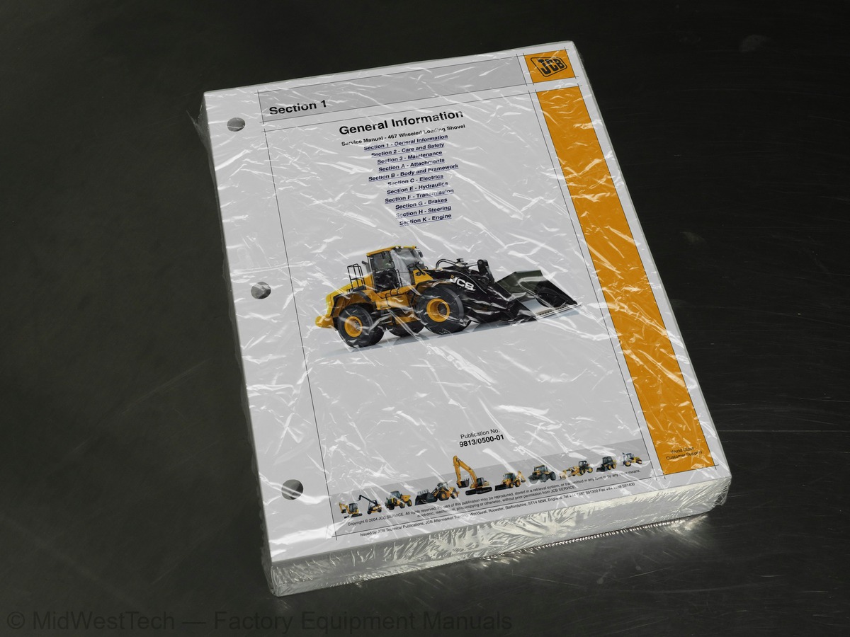
JCB 467 Wheeled Loading Shovel Service Manual
746 pages · Publication 9813-0500-01
Added to your cart. View cart
- Models
- 467 Wheeled
- Manual type
- Service Manual
- Pages
- 746
- Publication
- 9813-0500-01
- Condition
- Brand new
What's inside
From the manual's own table of contents: 1 sections, 211 entries. See sample pages (PDF, 348 KB)
General131 topics
- About this Publication
- Schematic Codes
- Moving a Disabled Machine
- Transporting the Machine
- Lifting the Machine
- Identification Plates
- Zinc Plated Fasteners and Dacromet Fasteners
- Numerical List Section B - Body and Framework
- Tool Detail Reference Section B - Body and Framework
- Numerical List Section C - Electrics
- Tool Detail Reference Section C - Electrics
- Numerical List Section E - Hydraulics
- Tool Detail Reference Section E- Hydraulics
- Numerical List Section F - Transmission
- Tool Detail Reference Section F - Transmission
- Numerical List Section G - Brakes
- Tool Detail Reference Section G - Brakes
- Sealing and Retaining Compounds
- Service Requirements
- Health and Safety
- Service Schedules
- Fluids, Lubricants and Capacities
- Tools
- Prepare the Machine for Maintenance
- Cleaning the Machine
- Checking for Damage
- Greasing
- Access Panels
- Heater and Air-Conditioning
- Brakes
- Electrical System
- Engine
- Fuel System
- Hydraulic System
- Transmission Drive Line
- Tyres and Wheels
- Windscreen Washers
- Connecting/Disconnecting Hydraulic Hoses
- Introduction
- Connecting the Hydraulic Hoses
- Disconnecting the Hydraulic Hoses
- Quick Release Couplings
- Removal and Installation
- Removal
- Installation
- Air Conditioning Option
- Related Topics
- Removal and Replacement
- Loader Arms - Shovel Tipping Lever
- Loader Arms Reset Mechanism
- Rivet Nuts
- Dismantling and Assembly
- Component Location
- Automatic Temperature Control Panel
- Air Conditioning and Automatic Temperature Control
- Fault Finding
- Automatic Temperature Control System
- General Electrical Data
- Fuses and Relays
- Using a Multimeter
- Battery
- Alternator
- Starter Motor
- Wire and Harness Number Identification
- Wiring Harness Repair
- Instrument Cluster
- Introduction to Fault - Finding Techniques
- Machines
- Wire and Harness Number Identification 467 Machines
- System Identification
- Machine JCB 467
- General Description
- Introduction to Hydraulic Schematic Symbols
- Hydraulic Circuit - 467 Machine
- Pump Operation
- Pump Pressure/Flow Regulator Valves
- Loader Valve - Operation
- Automatic Carry Control System (ACCS)
- Hydraulic Contamination
- Venting the Hydraulic Pressure
- Connecting and Disconnecting Hydraulic Hoses
- Pressure Testing
- Hydraulic Fault Finding
- Manifold Valve Block
- Loader Control Hydraulic Valve Block
- Precautions During Use
- Typical Ram
- Axles 467
- Unit Identification
- Axles
- Transmission
- Introduction and Description
- Preparation
- Powershift Transmission Description
- Transmission Components
- Torque Converter 1- Function
- Transmission Design
- Transmission Control
- Transmission Charge Pump 4
- Electro - Hydraulic Control 3
- Optional Power Take Off Shafts 5
- Multi-Plate Clutch Packs 6, 7 and 8
- Service Points/Component Location
- Service Measuring Points and Connections
- Component and Hydraulic Service Lines
- Hydraulic Circuit Diagram
- Transmission Hydraulic Circuit - Description
- Switches, Controllers, Transmitters and Sensors
- Preparatory Notes when Checking the Transmitters and Sensors
- Steering Column Controller
- Loader Controller
- Electro-Hydraulic Control Unit
- Disassembly and Assembly
- Transmission - Disassembly
- Converter Drive - Removal
- Input Shaft, Pump/Power Take Off - Disassembly
- First Power Take Off Version Only
- Transmission Pump - Removal
- moval
- First Power Take Off Version - Remove the Ball Bearing Race and Driver
- Third and Fourth Power Take Off Version
- Lay Shaft - Removal
- Inductive and Speed Transmitters - Removal
- Output Shaft Standard Version - Removal
- Output Shaft Park Brake Version - Removal
- Clutches and Lay Shaft - Removal
- Multi Disc Clutches - Removal
- Second Power Take Off - Removal
- Clutch K3/K4 - Disassembly
- Clutch KR/K2 - Disassembly
- Clutch Packs KV/K1 - Disassembly
Section F - Transmission79 topics
- Transmission - Assembly
- Power Take Off
- Second Power Take Off - Assembly
- Third/Fourth Power Take Off
- Intermediate Gear End Float -Adjustment
- Clutch Pack K4/K3 - Assembly
- Clutch K4 - Plate Assembly Order
- Clutch Pack Plate Clearance - Checking
- Spur Gear K4 - Assemble and Install
- Clutch K3 - Clutch Plate Assembly Order
- Spur Gear K3 - Assemble and Install
- Multi Plate Clutch KR/K2 - Assembly
- Clutch Pack KR - Assembly
- Clutch K2 - Check the Clutch Plate Clearance
- Clutch KR - Spur Gear Assembly
- Multi Plate Clutch Pack K2 - Assembly
- Clutch Pack K2 - Plate Clearance
- Spur Gear K2 - Assembly
- Multi Plate Clutch KV/K1 - Assembly
- Multi Plate Clutch KV - Assembly
- Clutch Pack KV - Plate Clearance
- Spur Gear Clutch KV - Assembly
- Clutch Pack K1 - Plate Clearance
- Multi Plate Clutch K1 - Assembly
- Spur Gear Clutch K1 - Assembly
- Lay Shaft Gear, Multi Plate Clutches and Output Gear - Assembly
- Transmission Housing Cover - Assembly
- Clutches KR/K2 - Bearing Pre-load Adjustment
- Clutches KV/K1 - Bearing Pre-load Adjustment
- Output Shaft - Assembly
- Output Shaft Bearing End-float - Adjustment
- Output Flange - Assembly
- Output Flange - Gap Adjustment
- Output Flange/Parking Disc - Assembly
- Output Flange Converter Side - Assembly
- Idler Shaft - Assembly
- Transmission Pump - Assembly
- Input Shaft Bearing End-float - Adjustment
- Converter Pressure Back-up Valve - Assembly
- Suction Strainer - Assembly
- Inductive and Speed Transmitters - Location
- Output Speed Transmitter - Installation
- Ancillary Components - Assembly
- Hydraulic Fitment - Assembly
- Plugs and Brackets - Assembly
- Converter Housing - Assembly
- Front Axle - Removal and Replacement
- Replacement
- Rear Axle - Removal and Replacement
- Axle Disassembly and Assembly
- Brake and Reduction Hub Disassembly
- Brake and Reduction Hub Assembly
- Axle Differential - Disassembly and Assembly
- Disassembly
- When Assembling
- Differential - Assembly
- Pinion Depth - Setting Procedure
- Limited Slip Differential - Assembly
- Basic Operation
- Servicemaster Display Panel
- Service Brakes
- Brake Circuit (467 Machines)
- Bleeding the System
- Hose Destinations
- Brake Valve
- Brake Pressure Setting
- System Testing
- Park Brake - 467 Machines
- Testing the Park Brake
- Adjusting the Pads
- Checking the Pad Wear
- Changing the Pads
- System Accumulators
- Charging the Accumulators
- Ergopower 4/5 WG-260 Transmission
- Pump
- Steering Valve - Operation
- Emergency Steering - Operation
- Emergency Steering System
Inside this manual
Real pages from this service manual (746 pages). Open the sample pages (PDF, 348 KB)
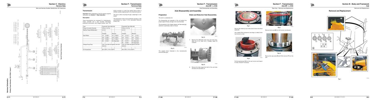
- Diagram, page 329: Section C - Electrics
- Specifications, page 461: Technical Data
- Repair procedure, page 604: Axle MT - L 3105
- Color page, page 601: Section F - Transmission
- Color page, page 161: Section B - Body and Framework
This is a service manual
Here's how it compares to the other manual types.
Service manual
Factory repair procedures and technical information such as specifications, troubleshooting, and wiring and hydraulic diagrams, for the models and systems the manual covers. See What's inside for its topics.
Operator's manual
Safe operation, controls, maintenance schedules, lubrication points, inspections, and basic checks. Repair procedures are in the service manual.
Parts manual
Illustrated diagrams with factory part numbers for identifying components and ordering parts. Repair procedures are in the service manual.
Engine service manuals are sometimes sold separately, since certain machine models were offered with more than one engine option.
What it's used for
Factory manual for in-house farm and construction shop use. Straightforward, complete, and easy to follow. It contains the OEM information dealership service departments and parts counters use to diagnose problems, identify components, and perform maintenance or repairs correctly.
Service shops and owner/operators who repair their own equipment
Identifying correct parts and seeing how assemblies come apart and go back together
Keeping equipment running with less downtime
Factory manual, 746 pages
Quantity one is the manual described above.
Fast free USA shipping
Ships in 1 business day.
60-day returns
Free if the mistake is ours. A manual ordered in error must come back unopened in its shrink-wrap; you pay return shipping and a 20% restocking fee applies. Return policy
Binder not included
Manuals over about 300 pages may need a standard 3-ring binder, which you can buy locally to keep the pages organized for shop use.
Questions about model, serial number, engine coverage or contents? Contact us before purchasing and we'll help confirm it's the right manual. Please verify the manual type, machine model, serial number range and engine coverage before purchasing: manuals ordered in error carry a 20% restocking fee (return policy).