JCB 515-40 Telehandler Service Manual
641 pages · Publication 9803-9900-4
Added to your cart. View cart
- Models
- 515-40
- Serial coverage
- from SN 1627500 to 1769999
- Manual type
- Service Manual
- Pages
- 641
- Publication
- 9803-9900-4
- Condition
- Brand new
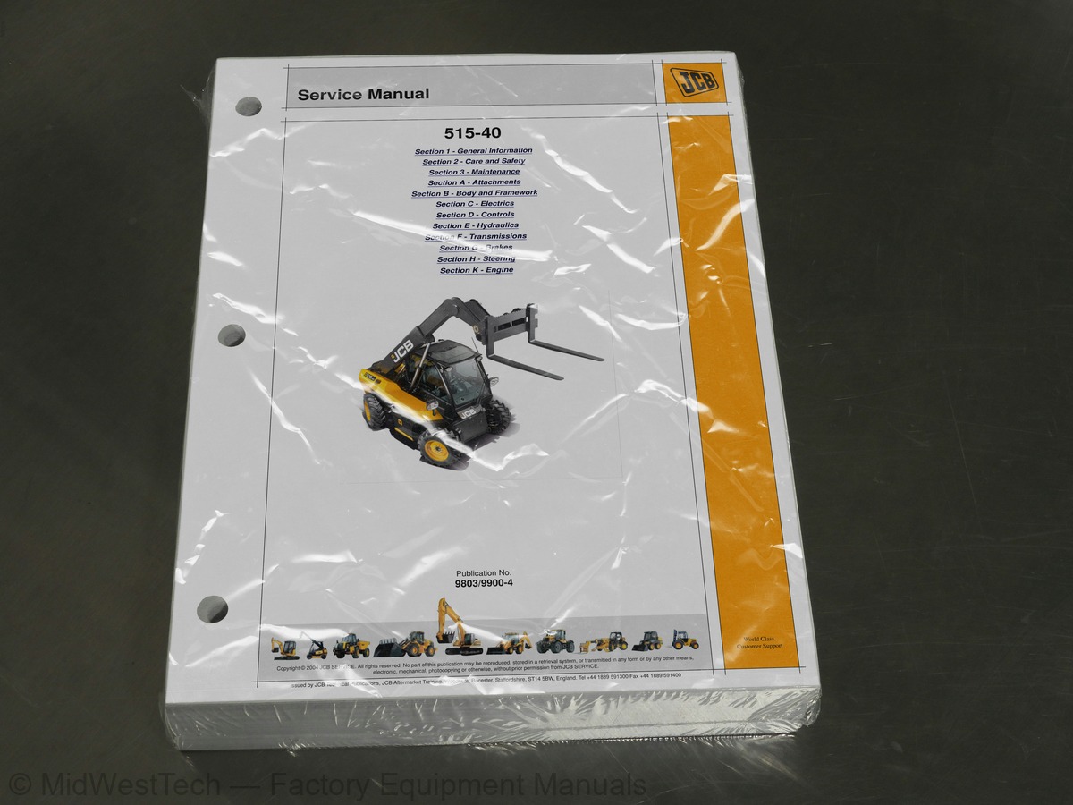
What's inside
From the manual's own table of contents: 136 topics. See sample pages (PDF, 365 KB)
- About This Publication
- Identifying Your Machine
- Moving a Disabled Machine
- Transporting the Machine
- Lifting the Machine
- Zinc Plated Fasteners and Dacromet Fasteners
- Hydraulic Connections
- Numerical List
- Tool Detail Reference
- Sealing and Retaining Compounds
- Colour Coding
- Service Requirements
- Health and Safety
- Service Schedules
- Fluids, Lubricants and Capacities
- Tools
- Prepare the Machine for Maintenance
- Cleaning the Machine
- Checking For Damage
- Greasing
- Oiling
- Access Panels
- Air Conditioning (if fitted)
- Cab Heater Filter
Show all 136 topics
- Brakes
- Electrical System
- Engine - Deutz
- Engine - Kohler
- Hydraulic System
- Tyres and Wheels
- Wheel Alignment
- Wear Pads
- Windscreen Washer Reservoir
- Fire Extinguisher (if fitted)
- Heating, Ventilation and Air Conditioning (HVAC)
- Load Moment Indicator (LMI)
- Cab Heating and Ventilation
- Air Conditioning
- Rivet Nuts
- Slide Hammer Kit
- Glazing
- Boom
- Removal and Replacement
- External Components
- Internal Components
- Cooling Pack Cover
- Fuel Sender Guard Plate
- Screen Guard
- Front Transmission Hose Guards
- Engine Side Panel
- Rear Engine Guard
- Underfloor Cover
- Hydraulic Tank Cover
- Rear Wheel Arch Panels
- Heater Assembly
- Air Conditioning Unit
- Condenser Unit
- Compressor
- General Technical Data
- Fuses and Relays
- Machine Electrical Schematics
- Using a Multimeter
- Battery
- Alternator
- Starter Motor
- Wire and Harness Number Identification
- Wiring Harness Repair
- Battery Tray
- Battery Isolator
- Drawings and Interconnection
- Component Identification
- Joystick
- Control Assembly
- Control Rod Assembly
- Specifications
- Operation Overview
- Main Services Pump
- Main Services Control Valve
- Hydraulic Operation and Schematics
- Introduction to Hydraulic Schematic Symbols
- Hydraulic Schematics Pre-LLMI
- Hydraulic Schematics - LLMI
- Main Hydraulic Services
- Hydraulic Contamination
- Venting/Releasing the Hydraulic Pressure
- Checking Pump Flow
- Relief Valve Testing
- Precautions During Use
- Dismantling and Assembly
- Overview
- Tyre Sizes and Pressures
- Hydrostatic Transmission
- Component Location
- Hydraulic Operation
- Electrical Operation
- System Priming Procedure
- Hydraulic Pressure Tests
- Transmission Pump
- Wheel Motors
- Relief Valves
- Solenoid Valve
- Pump and Engine Coupling
- Front Motor - Removal and Replacement
- Rear Motor - Removal and Replacement
- Wheel Motor - Dismantling and Assembly
- Inflating the Tyres
- Changing a Wheel
- Service Brakes
- Park Brake
- General Description
- Inching Control
- Brake System
- Hydraulic Steer Unit
- Priority Valve
- Steer Circuit Schematic
- Introduction
- Troubleshooting
- Re-phasing the Wheels
- Bleeding the System
- Dismantle and Assemble
- Adjustment
- Typical Engine Identification Number
- Specification
- Starting System
- Cold Start Glow Plugs
- Deutz - Removal and Replacement
- Kohler - Removal and Replacement
- Engine Oil Pressure Switch
- Engine Coolant Temperature Switch
- Removal and Replacement - Duetz
- Removal and Replacement - Kohler
- Removal and Replacement - Deutz
- Throttle Cable
- Cooling Fan Motor
- Reversible Fan
- Kohler Engine
Inside this manual
Real pages from this service manual (641 pages). Open the sample pages (PDF, 364 KB)
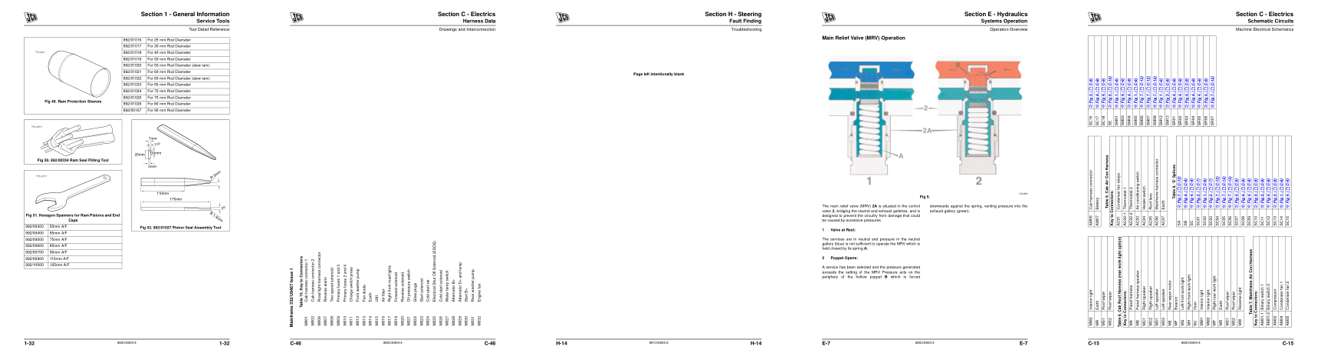
- Specifications, page 37: Section 1 - General Information
- Diagram, page 325: Section C - Electrics
- Troubleshooting, page 559: Section H - Steering
- Color page, page 380: Section E - Hydraulics
- Color page, page 294: Section C - Electrics
This is a service manual
Here's how it compares to the other manual types.
Service manual
Factory repair procedures and technical information such as specifications, troubleshooting, and wiring and hydraulic diagrams, for the models and systems the manual covers. See What's inside for its topics.
Operator's manual
Safe operation, controls, maintenance schedules, lubrication points, inspections, and basic checks. Repair procedures are in the service manual.
Parts manual
Illustrated diagrams with factory part numbers for identifying components and ordering parts. Repair procedures are in the service manual.
Engine service manuals are sometimes sold separately, since certain machine models were offered with more than one engine option.
What it's used for
Factory manual for in-house farm and construction shop use. Straightforward, complete, and easy to follow. It contains the OEM information dealership service departments and parts counters use to diagnose problems, identify components, and perform maintenance or repairs correctly.
Service shops and owner/operators who repair their own equipment
Identifying correct parts and seeing how assemblies come apart and go back together
Keeping equipment running with less downtime
Factory manual, 641 pages
Quantity one is the manual described above.
Fast free USA shipping
Ships in 1 business day.
60-day returns
Free if the mistake is ours. A manual ordered in error must come back unopened in its shrink-wrap; you pay return shipping and a 20% restocking fee applies. Return policy
Binder not included
Manuals over about 300 pages may need a standard 3-ring binder, which you can buy locally to keep the pages organized for shop use.
Questions about model, serial number, engine coverage or contents? Contact us before purchasing and we'll help confirm it's the right manual. Please verify the manual type, machine model, serial number range and engine coverage before purchasing: manuals ordered in error carry a 20% restocking fee (return policy).