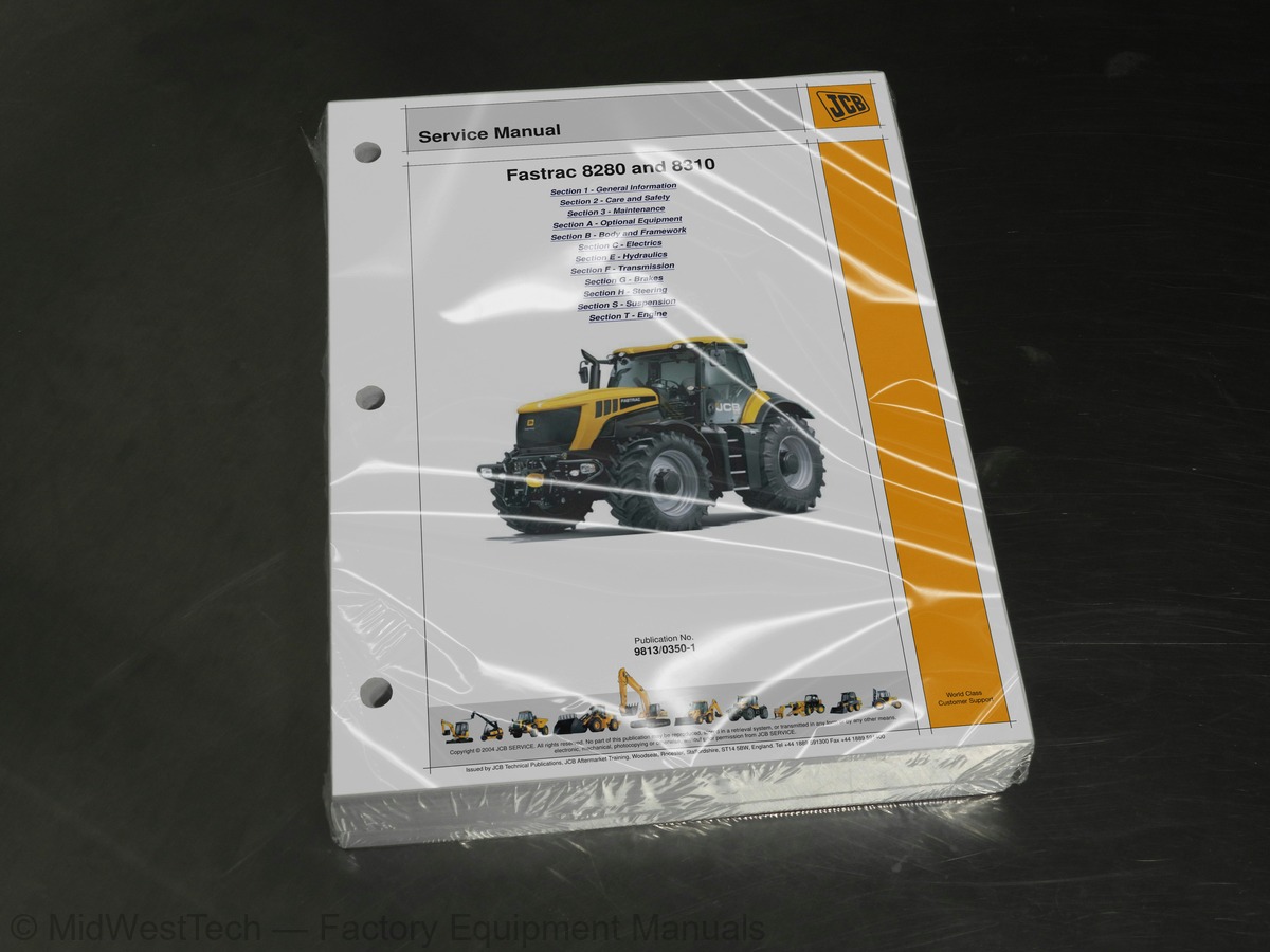
JCB Fastrac 8280, 8310 Tractor Service Manual
749 pages · Publication 9813-0350-1
Added to your cart. View cart
- Models
- Fastrac 8280, 8310
- Manual type
- Service Manual
- Pages
- 749
- Publication
- 9813-0350-1
- Condition
- Brand new
What's inside
From the manual's own table of contents: 2 sections, 265 entries. See sample pages (PDF, 384 KB)
General68 topics
- Identifying your Machine
- Identification Plate
- ROPS and FOPS Certification Labels
- Zinc Plated Fasteners and Dacromet Fasteners
- Introduction
- Zinc Plated Fasteners (golden finish)
- Dacromet Fasteners (mottled silver finish)
- Hydraulic Connections
- O' Ring Face Seal System
- Torque Stop' Hose System
- Numerical List
- Tool Detail Reference
- Section B - Body and Framework
- Section C - Electrics
- Section E - Hydraulics
- Section F - Transmission
- Section G - Brakes
- Section S - Suspension
- Sealing and Retaining Compounds
- Safety Check List
- Safety - Yours and Others
- General Safety
- Operating Safety
- Maintenance Safety
- Service Requirements
- Health and Safety
- Service Schedules
- Fluids, Lubricants and Capacities
- Carrying Tools onto the Machine
- Preparing the Machine for Maintenance
- Cleaning the Machine
- Checking for Damage
- Seats and Seat Belts
- Greasing
- Access Panels
- Air Conditioning and Heater
- Brakes
- Electrical System
- Engine
- Fuel System
- Hydraulic System
- Transmission
- Tyres and Wheels
- Power Take-off (PTO)
- Windscreen Washer
- Automatic Trailer Coupling (Optional)
- Position Sensor Calibration
- Accessing the Calibration Mode
- Calibration
- PTO Drive Shaft and Flexible Couplings
- Removal and Replacement
- PTO Gearbox
- Dismantling
- Assembly
- PTO Clutch Dismantling and Assembly
- Operation Overview
- Automatic Draft Control
- Fault Finding
- Air Conditioning
- Heater/Air Conditioning Controls
- Temperature Control
- Safety Procedures
- Leak Testing
- Compressor Clutch
- Removal
- Replacement
- Glass
- Direct Glazing
Section C - Electrics136 topics
- Using a Multimeter
- Measuring DC Voltage
- Measuring Resistance
- Measuring Continuity
- Measuring Frequency
- Testing a Diode or a Diode Wire
- Wire and Harness Number Identification
- Wire Numbers and Functions
- Wiring Harness Repair
- Repair Procedure
- Location
- Fuses on the PCB
- GPS and Work Light Fuses
- Fuses in the Pannier
- Engine-mounted Fuse
- Relay Identification
- Starter, Alternator, PCB Battery Fuses
- PCB Ignition Relays and Fuses
- Road Lights
- Fastrac Central Controller (ECU 1)
- Touch Screen (DECU), Instrument Panel (Unideck)
- Networks
- Heater, Ventilation, Air Conditioning (HVAC), Heated Screens
- Radio, Mirrors, Work Lights (MVEC), Auxiliary Sockets, Air Drier
- Wash/Wipe, Brakes, Draft Control
- Spool Valve, Hitch Controls, Engine
- Earths
- Drawings and Interconnection
- Harnesses
- Fault Codes
- ABS ECU
- Fastrac Central Controller - ECU1
- EMS Dashboard
- Gearbox ECU
- Auxiliary ECU
- Engine ECU
- Work Lights (ECU1 - Fastrac Central Controller)
- DECU
- Rear Hitch
- Suspension
- Front Hitch Slice
- Green Slice
- Blue Slice
- Brown Slice
- Grey Slice
- Main Components Diagram
- Description
- ECU Locations
- Why Use Service Master?
- Identify Poor Maintenance
- Access Machine Set Up Data
- Re-Programming ECUs
- Summary
- What is Service Master?
- CANbus Communications System
- Service Master Structure
- How to Set Up Service Master
- Install Service Master
- Start Service Master
- Load the DLA Laptop Driver Software
- Configure the DLA Type and Communications Port
- Check the DLA Firmware File
- Connect Service Master to the Machine CANbus
- Maintenance
- Test Procedures
- High Rate Discharge Test
- Specific Gravity Testing
- Disconnection and Connection
- Description and Programming
- Instruments
- Warnings (Audible/Visual)
- Warnings (Visual only)
- EMS Programming - Level 1
- Operation
- Continuously Variable Transmission (CVT)
- Touch Screen Settings
- Programming the Joystick Push Buttons
- Automatic Field Settings
- Wheel Slip
- Headland Management System
- Service Information
- Accessing Calibration Menu
- Joystick
- Steering Angle
- Screen Calibration
- External Hydraulics
- Flow Rates
- Pressures
- Spool Valve
- Other Hydraulic Circuits
- Introduction to Hydraulic Schematic Symbols
- General (Basic and Functional Symbols)
- Control Valves
- Example of Schematic Circuit
- Electronically Actuated Spool Valve
- Maximum System Pressure
- Pilot Stand-by Pressure
- Dismantling and Assembly
- Shuttle Valves
- Configuration
- Valve Slice Dismantling
- Accessing the Configuration Mode
- Valve Slices Currently Configured
- Configuring `Bosch' Slices
- Piston Pump (External Hydraulics)
- Control Valve
- Sealing the Driveshaft
- Pump Dismantling and Assembly
- Gear Pump (Suspension and Steering)
- Rear Lift Ram
- Pressure Settings
- Axles
- Front Axle
- Rear Axle
- Low Pressures
- High Pressure
- Differential Lock and PTO
- Differential Lock
- PTO Speed Pressures
- Main Component Identification
- Actuator Unit
- Hydraulic Circuit
- Valve Block 1
- Valve Block 2
- High Pressure Relief Valve, Forward/Reverse
- Purge Valve
- Operation in Different Modes
- Engine at idle, Machine stopped
- 99% Hydrostatic - 1% Mechanical
- 50% Hydrostatic - 50% Mechanical
- rev/min
- faster than engine
- Forward and Reverse High Pressure Relief Valves
- Filling the Transmission Oil
- Master Cylinder
- Filling and Bleeding the System
Section F - Transmission59 topics
- Component Key
- Inspection
- Drive Head
- Rear PTO Input Shaft
- Rear PTO Gearbox
- Brake System
- Parking Brake
- Foot (Service) Brake
- Safety
- Front Brake Circuit
- Rear Brake Circuit
- Trailer/Parking Brake Circuit
- Parking Brake Circuit
- Hydraulic Trailer Brakes (if fitted)
- Tractor ABS System
- General Description
- Air Drier/Unloader Valve
- Circuit Protection Valve
- Pressure Modulating Valves
- Non-Return Air Valve
- Trailer Brake Hydraulic Valve
- Testing
- Brake System Bleeding
- When Dismantling
- When Assembling
- Fault Tables
- Low Pressure Warning Lights On
- Service Brakes Poor
- Poor Front Brakes, Good Rear Brakes
- Poor Rear Brakes, Good Front Brakes
- Trailer Brakes Poor
- Park Brake Not Holding
- Park Brake Not Releasing
- Pressures and Flow Rates
- Steer Box
- Steering Relief Valve (All Machines)
- Steering Relief Valves (GPS Ready Machines only)
- Preparation
- GPS Steering Main Relief Valve
- GPS Steering Pilot Relief Valve
- Related Error Codes
- Standard Machines
- GPS Ready Machines
- When Removing
- When Replacing
- Steering Limiters
- Setting
- Rear Suspension
- Discharging Hydraulic Pressure
- Additional Circuit Discharging
- Control Arm
- Panhard Rod
- Electronic Control
- Pressure Testing
- Pressure Maintenance Valve
- Suspension Cylinder
- Potentiometer
- Anti-roll Bar
- ‘V’ Link
Inside this manual
Real pages from this service manual (749 pages). Open the sample pages (PDF, 383 KB)

- Troubleshooting, page 329: Fault Finding Tables
- Diagram, page 439: Section F - Hydraulics
- Specifications, page 681: Section H - Steering
- Color page, page 459: Section E - Hydraulics
- Color page, page 614: Section F - Transmission
This is a service manual
Here's how it compares to the other manual types.
Service manual
Factory repair procedures and technical information such as specifications, troubleshooting, and wiring and hydraulic diagrams, for the models and systems the manual covers. See What's inside for its topics.
Operator's manual
Safe operation, controls, maintenance schedules, lubrication points, inspections, and basic checks. Repair procedures are in the service manual.
Parts manual
Illustrated diagrams with factory part numbers for identifying components and ordering parts. Repair procedures are in the service manual.
Engine service manuals are sometimes sold separately, since certain machine models were offered with more than one engine option.
What it's used for
Factory manual for in-house farm and construction shop use. Straightforward, complete, and easy to follow. It contains the OEM information dealership service departments and parts counters use to diagnose problems, identify components, and perform maintenance or repairs correctly.
Service shops and owner/operators who repair their own equipment
Identifying correct parts and seeing how assemblies come apart and go back together
Keeping equipment running with less downtime
Factory manual, 749 pages
Quantity one is the manual described above.
Fast free USA shipping
Ships in 1 business day.
60-day returns
Free if the mistake is ours. A manual ordered in error must come back unopened in its shrink-wrap; you pay return shipping and a 20% restocking fee applies. Return policy
Binder not included
Manuals over about 300 pages may need a standard 3-ring binder, which you can buy locally to keep the pages organized for shop use.
Questions about model, serial number, engine coverage or contents? Contact us before purchasing and we'll help confirm it's the right manual. Please verify the manual type, machine model, serial number range and engine coverage before purchasing: manuals ordered in error carry a 20% restocking fee (return policy).