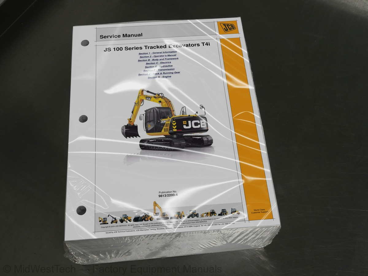
JCB JS115, JS130, JS145, JS160, JS180, JS190 T4i Tracked Excavator Service Manual
1,500 pages · Publication 9813-2200-4
Added to your cart. View cart
What's inside
From the manual's own table of contents: 381 topics. See sample pages (PDF, 444 KB)
- Identifying Your Machine
- Introduction
- Scope
- Format
- Left Side, Right Side
- Hydraulic Schematic Codes
- Maintenance Schedules
- Parking the Machine and Making it Safe
- Venting the Hydraulic Pressure
- Connecting/Disconnecting Hydraulic Hoses
- Battery Disconnection/Connection
- Removing and Replacing Components
- Battery Charging System Precautions
- Gas Hydraulic Bladder Accumulators
- Sealing and Retaining Compounds
- Zinc Plated Fasteners and Dacromet Fasteners
- Hydraulic Connections
- `Positional Type' Hydraulic Adaptors
- Numerical List
- Tool Detail Reference
- Acronyms Glossary
- Machine Model and Serial Number
- Using the Manual
- Left-Hand Side, Right-Hand Side
Show all 381 topics
- Cross References
- Safety - Yours and Others
- Safety Warnings
- General Safety
- Clothing and Personal Protective Equipment (PPE)
- General
- Product Compliance
- Intended Use
- Log Moving/Object Handling
- Optional Equipment and Attachments
- Danger Zone
- Main Component Locations
- Machine
- Engine
- Operator Protective Structure
- Safety Label Identification
- Component Locations
- Operator Door
- Front Window
- Side Window
- Sunblind
- Suspension Seat
- Heated Seat Controls
- Seat Ventilation Controls
- Inertia Reel Seat Belt
- Static Seat Belt
- Track Controls
- Travel Speed Selector
- Work Lights
- Beacon
- Seat Heater
- Seat Ventilation
- Control Locks
- Radio Mute
- Excavator Arm Quickhitch
- Engine Stop Switch
- Slew Lock
- Cushion
- Window Washer
- Window Wipers
- Front Lower Window Wiper
- Cab Raise/Lower
- Ignition Switch
- Cab Interior Light
- Auxiliary Power Socket
- Instrument Panel
- Air-Conditioning Controls
- Control Layouts
- Excavator Arm Controls
- Dozer Blade Controls
- Auxiliary Circuit Controls
- Worksite Safety
- Risk Assessment
- Emergency Exit
- Immobilizer
- Warming Up
- Preparing for Worksite Travel
- Control Lock
- Towing Other Equipment
- Load Charts
- Overload Warning System
- Preparing to Use the Excavator Arm
- Lifting With the Excavator Arm
- Digging
- Checking the Bucket Linkage
- Dipper Stroke Limiter
- Dozing and Grading
- Scraping and Cutting
- Backfilling
- Driving on Slopes
- Working on Slopes
- Getting the Machine Unstuck
- Jump-Starting the Engine
- Retrieval
- Excavator Arm (Emergency Operation)
- Loading a Machine onto the Transporting Vehicle/Trailer
- Unloading a Machine from the Transporting Vehicle/Trailer
- Operating in Low Temperatures
- Operating in High Temperatures
- Cab Filters
- Low Fuel Levels
- Filling the Tank
- Attachments for your Machine
- Impact Protection
- Bucket Teeth
- Preparing the Machine
- Put the Machine into Storage
- During Storage
- Take the Machine out of Storage
- JCB Plantguard
- Construction Equipment Security and Registration Scheme (CESAR)
- LiveLink
- Anti-Vandal Guards
- Owner/Operator Support
- Service/Maintenance Agreements
- Obtaining Spare Parts
- Fluids and Lubricants
- How to Use the Maintenance Schedules
- Maintenance Intervals
- Pre-start Cold Checks, Service Points and Fluid Levels
- Functional Tests and Final Inspection
- Maintenance Position (Excavator Arm Lowered)
- Battery Cover
- Engine Compartment Cover
- Hydraulic Compartment Cover
- Radiator Cover
- Toolbox
- Slew Ring Bearings
- Pivot Pins
- Seat
- Seat Belt
- Controls
- Drive Belt
- Pre-Cleaner
- Dust Valve
- Tank
- Fuel Filter
- Water Separator
- Coolant
- Cooling Pack
- Steel
- Idler Wheels
- Rollers
- Services
- Cylinder Rams
- Battery
- Battery Isolator
- Fuses
- Relays
- Fire Extinguisher
- Dimensions
- Weights
- Excavator Arm Dimensions and Performance
- Driving Performance
- Noise Data
- Vibration Data
- Fuel
- Engine Emissions
- Machine Data
- Machine Service Record Sheet
- Air Conditioning (option)
- Automatic Temperature Control (ATC) System
- Air Conditioning
- HV/HVAC Unit
- Air Conditioning Compressor
- Cab Structure
- Removal and Replacement
- Scheduled Tasks
- Doors and Locks
- Excavator Lever and Pedal Locks
- Slew Ring Pinion and Gear Teeth
- Fit For Purpose Test
- Cab Heater/Air-Conditioning Filter
- Circuit Symbols
- Circuit Concepts
- Pulse Width Modulation (PWM)
- Using a Multimeter
- Schematic Diagrams - Machines with Ecomax Engines
- Schematic Diagrams - JS160, JS190 Machines with Dieselmax Engines . C
- gines
- Maintenance
- Test Procedures
- Disconnection and Connection
- Cab Fuse and Relay Box - Connector Identification
- Installation and Interconnections
- Earth Points
- Harness Drawing List, JS115 - JS190
- Drawings
- Connector Codes
- Wire Numbers and Functions
- Wiring Harness Repair
- CANbus System
- Machine Electronic Control Unit (MECU)
- Hydraulic Electronic Control Unit (HECU)
- Display ECU (DECU)
- Engine ECU
- Testing of ECU Inputs + Outputs
- Battery Power Supply and Distribution
- Ignition Power Supply and Distribution
- Engine Start/Stop - Ecomax Engines
- Engine Start/Stop - Dieselmax Electronic F.I. Engines
- Engine Start/Stop - Dieselmax Mechanical F.I. Engines
- Engine Cranking
- Engine 24V to 12V Converter - Engines with Electronic F.I
- Engine Fuse and Relay Box - Engines with Electronic F.I
- Engine Fuel Lift Pump
- Engine Throttle and Power Mode Control
- Throttle Actuator - Engines with Mechanical F.I
- Inlet Manifold Heater Relay
- Engine Cold Idle
- Ambient Air Temperature Sensor
- Engine Automatic Warm Up - Engines with Electronic F.I
- Engine Automatic Idle
- Variable Geometry Turbo (VGT) Actuator - Ecomax Engines
- Exhaust Gas Re circulation (EGR) Actuator - Ecomax Engines
- TMAF Sensor - Engines with Electronic F.I
- Electro Viscous Fan
- Engine Coolant Temperature Switch - Engines with Electronic F.I
- Engine Coolant Temperature Switch - Engines with Mechanical F.I
- Engine Coolant Level Switch
- Engine Oil Level Switch
- Engine Speed Sensor - Engines with Mechanical F.I
- Vacuum Switch
- Fuel Level Sensor
- Water In Fuel (WIF) Sensor - Engines with Electronic F.I
- Water In Fuel (WIF) Sensor - Engines with Mechcanical F.I
- Alternator
- Refuelling Pump
- Station Solenoid Valve
- Pressure Switches
- 3-Speed Travel
- Controls Enable (Lever Lock)
- Controls Enable (Lever Lock ISO)
- Slew Brake and Slew Lock
- Pump Proportional Control Solenoid
- Cushion Control
- Overload Caution (option)
- Boost Pressure
- Maximum Flow Cut Solenoid
- Hydraulic Oil Temperature Sensor
- Quickhitch (option)
- Camera System
- Standard Work Lights
- Cab Work Lights
- Horn
- Wipers and Washers
- Cab Interior Lamp
- to 12 Volt Converter
- HVAC Control
- Overview
- Selecting the Diagnostic Mode Screen
- Operation Overview
- Engine ‘P’ Codes
- Cab Area ‘B’ Codes
- Chassis ‘C’ Codes
- CANbus ‘U’ Codes
- Why Use ServiceMaster?
- What is Servicemaster?
- How to Set-up Servicemaster
- Tools Suites
- Diagnostics Connectors
- Servicemaster Machine Selection
- Servicemaster Engine Selection
- Starter Motor
- General Data
- Introduction to Hydraulic Schematic Symbols
- Hydraulic Schematics
- Servo Line
- Servo Pressure and Return Line
- Hydraulic Pump Regulation
- Neutral Circuit
- Straight Line Travel
- Travel - Slow Speed
- Boom Up
- Boom Down
- Dipper Out
- Dipper In
- Bucket Opening
- Bucket Close
- Slew Circuit
- 100% Slew Lock
- Bi-Direction / Hammer Auxiliary
- Bi-Direction / Tool Select / Hammer Auxiliary
- Low Flow Tool Select Auxiliary
- ISO/SAE Controls
- Description
- Hydraulic Pump Operation
- Hydraulic Pump Removal and Replacement - JS115-145
- Hydraulic Pump Removal and Replacement - JS160-190
- Hydraulic Pump Dismantling and Assembly
- Regulator Dismantling and Assembly
- Operation
- Dismantling and Assembly
- Specification
- Motor Operating Principles
- Slew Brake Operation
- Fault Finding
- Slew Motor Configuration
- Reduction Gear Structure and Working Principles
- Dismantling
- Assembly
- Precautions During Use
- Maintenance Specifications
- Make the Machine Safe
- Pressure Testing - General
- Pressure Relief Valve Location
- Main Relief Valve (MRV) Pressure
- Servo Relief Pressure
- Slew Motor Pressure Relief
- Auxiliary Relief Valves
- Travel Motor Relief Pressure
- Hydraulic Contamination
- Main Control Valve
- Relief Valve
- Hydraulic System
- Slew Motor
- Hydraulic Pump
- Hydraulic Rams
- Fault Finding Tests
- Test 001: Testing Negative Control Signal
- Test 002: Test Max Flow Signal
- Test 003: Testing Main Pump Pressure
- Test 004: Testing Horsepower Control
- Test 005: Checking the Operation of the Main Hydraulic Spool
- Test 006: Test the Pressure Switches
- Test 007: Testing Engine Speed Settings
- Test 008: Testing Machine Cycle Times
- Test 011: Testing Swing Brake Pressure
- Test 012: Testing Track Motor Relief Valve Settings
- Test 013: Testing Track Motor Drain Line Flow Rate
- Test 014: Testing the High Speed Tracking Setting
- Test 015: Testing the Low Speed Tracking Setting
- Test 016 - Flow Testing Hydraulic Pumps - Record Sheet
- Test 017: Testing Slew Bearing
- Ram Creep Tests - All Services
- Service Points
- Hydraulic Oil
- Hydraulic Tank Breather
- Return Filter
- Drain Filter
- Suction Strainer
- Cushion Valve Filter
- Major Component Mounting Bolts
- Servo Filter Element
- Plexus Filter Element
- Breaker In-Line Filter Element
- Relief Valves
- Oil Cooler
- Slew Gearbox Oil
- Slew Brake
- Steering Line Filter
- Track Motor/Gearbox
- Transmission
- Dismantling and Assembly - JS115, JS130, JS145
- Dismantling and Assembly - JS160, JS180, JS190
- Start Up and Running In
- Dismantling and Assembly - JS115, JS130, 145
- Track Gearbox
- Track Plate Bolts
- Removal
- Replacement
- Scheduled Procedures
- JCB Ecomax Engine
- JCB Dieselmax Engines
- Engine Mounts
- Engine Oil and Filter
- Fan Belt
- FEAD Belt
- Crankcase Ventilation Filter
- Air Inlet
- Exhaust System
- Air Filter Elements
- Main Fuel Filter and Sedimenter
- Engine Fuel Filter S1
- Engine Fuel Filter S2
- Primary Fuel Filter
- Maximum No Load Speed
Inside this manual
Real pages from this service manual (1,500 pages). Open the sample pages (PDF, 443 KB)
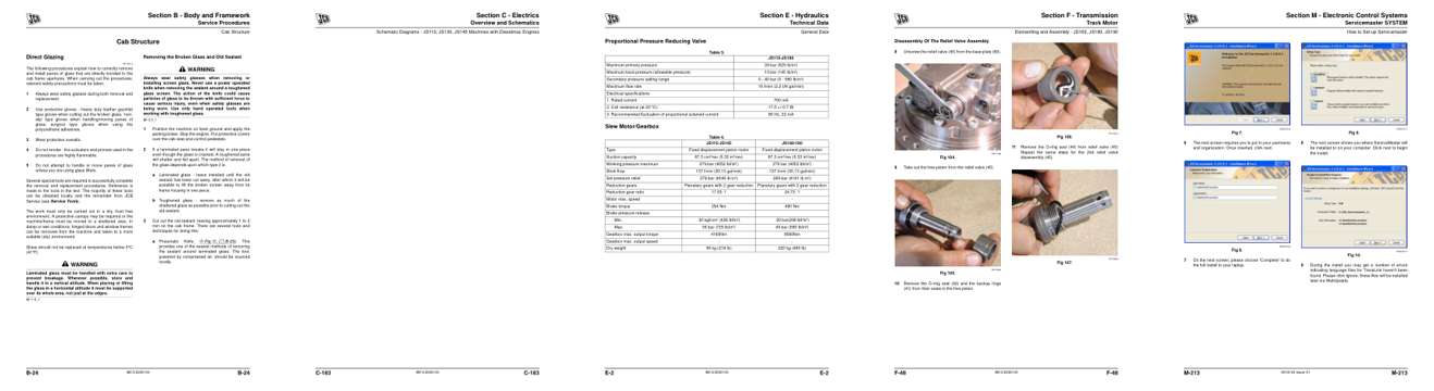
- Repair procedure, page 500: Section B - Body and Framework
- Diagram, page 707: Overview and Schematics
- Specifications, page 1,006: Section E - Hydraulics
- Color page, page 1,360: Section F - Transmission
- Color page, page 971: Section M - Electronic Control Systems
This is a service manual
Here's how it compares to the other manual types.
Service manual
Factory repair procedures and technical information such as specifications, troubleshooting, and wiring and hydraulic diagrams, for the models and systems the manual covers. See What's inside for its topics.
Operator's manual
Safe operation, controls, maintenance schedules, lubrication points, inspections, and basic checks. Repair procedures are in the service manual.
Parts manual
Illustrated diagrams with factory part numbers for identifying components and ordering parts. Repair procedures are in the service manual.
Engine service manuals are sometimes sold separately, since certain machine models were offered with more than one engine option.
What it's used for
Factory manual for in-house farm and construction shop use. Straightforward, complete, and easy to follow. It contains the OEM information dealership service departments and parts counters use to diagnose problems, identify components, and perform maintenance or repairs correctly.
Service shops and owner/operators who repair their own equipment
Identifying correct parts and seeing how assemblies come apart and go back together
Keeping equipment running with less downtime
Factory manual, 1,500 pages
Quantity one is the manual described above.
Fast free USA shipping
Ships in 1 business day.
60-day returns
Free if the mistake is ours. A manual ordered in error must come back unopened in its shrink-wrap; you pay return shipping and a 20% restocking fee applies. Return policy
Binder not included
Manuals over about 300 pages may need a standard 3-ring binder, which you can buy locally to keep the pages organized for shop use.
Other editions and similar models
Questions about model, serial number, engine coverage or contents? Contact us before purchasing and we'll help confirm it's the right manual. Please verify the manual type, machine model, serial number range and engine coverage before purchasing: manuals ordered in error carry a 20% restocking fee (return policy).