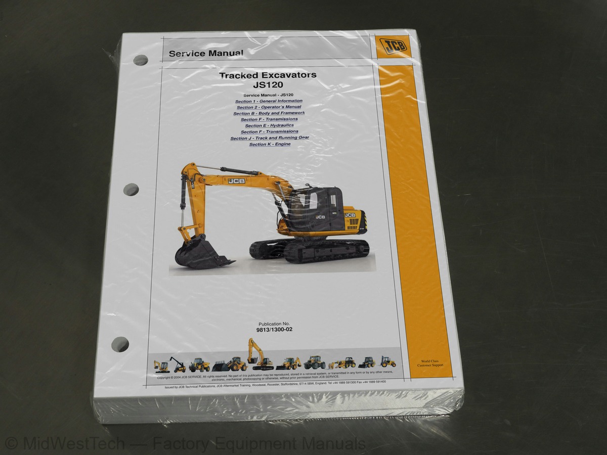
JCB JS120 Tracked Excavator Service Manual
647 pages · Publication 9813-1300-02
Added to your cart. View cart
- Models
- JS120
- Serial coverage
- JS120 from SN 1777500 to 1777999 onwards, JS120 Upgrade from SN 02425471 to 02426000
- Manual type
- Service Manual
- Pages
- 647
- Publication
- 9813-1300-02
- Condition
- Brand new
What's inside
From the manual's own table of contents: 3 sections, 271 entries. See sample pages (PDF, 442 KB)
General199 topics
- About this Manual
- Machine Model and Serial Number
- Using this Manual
- Left Side, Right Side
- Cross References
- Machine Description
- The JCB Tracked Excavator
- Intended Use
- Main Component Locations
- Identifying Your Machine
- Machine Identification Plate
- Component Identification Plate
- Zinc Plated Fasteners and Dacromet Fasteners
- Introduction
- Bolts and Screws
- Hydraulic Connections
- O' Ring Face Seal System
- Torque Stop' Hose System
- Numerical List
- Tool Detail Reference
- Section B - Body and Framework
- Section C - Electrics
- Section E - Hydraulics
- Section K - Engine
- Sealing and Retaining Compounds
- Colour Coding
- Hydraulic Schematic Colour Codes
- Acronyms Glossary
- Using the Manual
- Left-Hand Side, Right-Hand Side
- Safety - Yours and Others
- Safety Warnings
- General Safety
- Clothing and Personal Protective Equipment (PPE)
- General
- Product Compliance
- Log Moving/Object Handling
- Optional Equipment and Attachments
- Danger Zone
- Machine
- Engine
- Safety Label Identification
- Component Locations
- Operator Door
- Front Window
- Side Window
- Sunblind
- Suspension Seat
- Inertia Reel Seat Belt
- Static Seat Belt
- Track Controls
- Travel Speed Selector
- Work Lights
- Control Locks
- Slew Lock
- Window Wipers
- Two Speed Range
- Ignition Switch
- Cab Interior Light
- Auxiliary Power Socket
- Instrument Panel
- Air-Conditioning Controls
- Face Level Fan
- Control Layouts
- Excavator Arm Controls
- Auxiliary Circuit Controls
- Worksite Safety
- Risk Assessment
- Emergency Exit
- Warming Up
- Preparing for Worksite Travel
- Control Lock
- Towing Other Equipment
- Preparing to Use the Excavator Arm
- Lifting With the Excavator Arm
- Digging
- Checking the Bucket Linkage
- Driving on Slopes
- Working on Slopes
- Getting the Machine Unstuck
- Jump-Starting the Engine
- Retrieval
- Excavator Arm (Emergency Operation)
- Loading a Machine onto the Transporting Vehicle/Trailer
- Unloading a Machine from the Transporting Vehicle/Trailer
- Operating in Low Temperatures
- Operating in High Temperatures
- Cab Filters
- Low Fuel Levels
- Filling the Tank
- Attachments for your Machine
- Connecting/Disconnecting Hydraulic Hoses
- Impact Protection
- Bucket Teeth
- Preparing the Machine
- Put the Machine into Storage
- During Storage
- Take the Machine out of Storage
- LiveLink
- Owner/Operator Support
- Service/Maintenance Agreements
- Obtaining Spare Parts
- Fluids and Lubricants
- How to Use the Maintenance Schedules
- Maintenance Intervals
- Pre-start Cold Checks, Service Points and Fluid Levels
- Functional Tests and Final Inspection
- Maintenance Position (Excavator Arm Lowered)
- Battery Cover
- Engine Compartment Cover
- Hydraulic Compartment Cover
- Toolbox
- Slew Ring Bearings
- Pivot Pins
- Seat
- Seat Belt
- Controls
- Drive Belt
- Pre-Cleaner
- Dust Valve
- Tank
- Fuel Filter
- Water Separator
- Coolant
- Cooling Pack
- Steel
- Idler Wheels
- Rollers
- Services
- Cylinder Rams
- Battery
- Battery Isolator
- Fuses
- Relays
- Window Washer
- Dimensions
- Weights
- Excavator Arm Dimensions and Performance
- Driving Performance
- Fuel
- Technical Data
- Machine Static Dimensions
- Dig Depth Chart
- Shipping Weight
- Travel Speeds
- Lift Capacities
- Life Capacity Full Circle
- System Charging
- Refrigerant Leaks Detections
- Lubrications
- System Flushing
- Air Conditioning
- System Initial Check Points
- Temperature Pressure Data
- System Diagnosis based on Pressures
- Gauges Reading Interpretation
- Noise from A/C System
- Unpleasant Odour from A/C System
- Cab Structure
- Direct Glazing
- Checks
- Cab Panel Removal
- Right Hand Cab Panels
- Left Hand Cab Panels
- General Data
- Main Hydraulic Pump
- Boom Ram
- Dipper Ram
- Bucket Ram
- Slew Motor
- Travel Gearbox
- Swing Gearbox
- Swing Motor
- Introduction to Hydraulic Schematic Symbols
- General (Basic and Functional Symbols)
- Control Valves
- Example of Schematic Circuit
- Pilot Circuit
- Neutral Circuit
- Travel-Single Speed
- Straight Line Travel
- Boom Up
- Boom Down
- Dipper Out
- Dipper In
- Bucket Opening
- Bucket Closing
- Swing
- Hydraulic Schematic
- Hydraulic Schematic (Serial Number - 2425471 to 2426000)
- Slew Circuit
- Slew Motor Configuration
- Reduction Gear Structure and working principles
- Pressure Relief Valve
- Main Relief Valve (MRV) Pressure
- Servo Relief Pressure
- Slew Motor Pressure Relief
- Auxiliary Relief Valves
- Travel Motor Relief Pressure
Section E - 140 topics
- Hydraulic Pump
- Removal and Replacement
- Removal
- Replacement
- Dismantling
- Inspection
- Regulator
- Regulator Dismantling and Assembly
- Assembly
- Operation
- Function
- Dismantling and Assembly
- Fault Finding
- Motor Operating Principles
- Slew Brake Operation
- Motor Does Not Rotate
- Motor Rotates in the Reverse Direction
- Motor Speed is Low
- Motor Brake Working Poorly
- Motor is Driven by Exterior Torque
- Oil Leakage
- Precautions on Use
- Structure of Motor and Relief Valve
- Disassembly
- Troubleshooting
- Precautions During Use
- Installation
- Caution During Use
- Maintenance, Inspection Points
- Typical Bucket Ram
- Typical Boom Ram
- Typical Dipper Ram
- Assembling and disassembling procedures
- Cylinder Disassembly
- Cylinder Assembly
- Do’s in a Hydraulic Cylinder
- Dont’s in a Hydraulic Cylinder
- Control Valve in General
- Relief Valve
- Hydraulic Rams
Section F - Transmissions12 topics
- Travel Equipment
- For safety
- Tools
- Standard tools
- Transmission
- Preparations
- Assembling hub
- Precautions during Installation
- Motor Bleeding
- Torque Setting
- Disamantling and Assembly
- Disassembly and Assembly
Section J - Track and Running Gear17 topics
- Component Identification
- Idler Wheel
- Functions of Undercarriage Groups
- Track Group
- Checklist for Undercarriage Parts
- Track and Running Gear
- Removal Instruction
- Track Adjustment - Instruction
- Removal of Roller Group from m/c
- Bottom Roller
- Roller Group Re-assembly
- Installing Roller Group On The Machine
- CRG Removal Instruction
- Installation Instruction
- Dismantling Instructions
- Assembly Instruction
- Idler Unit
Inside this manual
Real pages from this service manual (647 pages). Open the sample pages (PDF, 442 KB)

- Specifications, page 218: Technical Data
- Diagram, page 308: Basic System Operation
- Troubleshooting, page 478: Fault Finding
- Color page, page 564: Section F - Transmissions
- Color page, page 591: Section F - Transmissions
This is a service manual
Here's how it compares to the other manual types.
Service manual
Factory repair procedures and technical information such as specifications, troubleshooting, and wiring and hydraulic diagrams, for the models and systems the manual covers. See What's inside for its topics.
Operator's manual
Safe operation, controls, maintenance schedules, lubrication points, inspections, and basic checks. Repair procedures are in the service manual.
Parts manual
Illustrated diagrams with factory part numbers for identifying components and ordering parts. Repair procedures are in the service manual.
Engine service manuals are sometimes sold separately, since certain machine models were offered with more than one engine option.
What it's used for
Factory manual for in-house farm and construction shop use. Straightforward, complete, and easy to follow. It contains the OEM information dealership service departments and parts counters use to diagnose problems, identify components, and perform maintenance or repairs correctly.
Service shops and owner/operators who repair their own equipment
Identifying correct parts and seeing how assemblies come apart and go back together
Keeping equipment running with less downtime
Factory manual, 647 pages
Quantity one is the manual described above.
Fast free USA shipping
Ships in 1 business day.
60-day returns
Free if the mistake is ours. A manual ordered in error must come back unopened in its shrink-wrap; you pay return shipping and a 20% restocking fee applies. Return policy
Binder not included
Manuals over about 300 pages may need a standard 3-ring binder, which you can buy locally to keep the pages organized for shop use.
Questions about model, serial number, engine coverage or contents? Contact us before purchasing and we'll help confirm it's the right manual. Please verify the manual type, machine model, serial number range and engine coverage before purchasing: manuals ordered in error carry a 20% restocking fee (return policy).