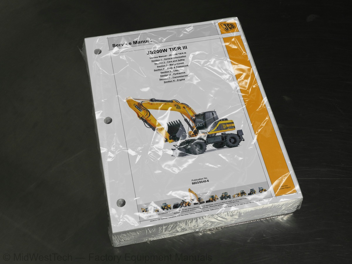
JCB JS200W Tier III Wheeled Excavator Service Manual
557 pages · Publication 9803-9540-6
Added to your cart. View cart
- Models
- JS200W Tier III
- Manual type
- Service Manual
- Pages
- 557
- Publication
- 9803-9540-6
- Condition
- Brand new
What's inside
From the manual's own table of contents: 3 sections, 397 entries. See sample pages (PDF, 409 KB)
General123 topics
- About this Manual
- Machine Model and Serial Number
- Using the Service Manual
- Section Numbering
- Left Side, Right Side
- Cross References
- Identifying Your Machine
- Machine Identification Plate
- FOPS Data Plate
- Component Identification Plates
- Zinc Plated Fasteners and Dacromet Fasteners
- Introduction
- Bolts and Screws
- Hydraulic Connections
- O' Ring Face Seal System
- Torque Stop' Hose System
- Numerical List
- Tool Detail Reference
- Section B - Body and Framework
- Section C - Electrics
- Section E - Hydraulics
- Section K - Engine
- Sealing and Retaining Compounds
- Colour Coding
- Hydraulic Schematic Colour Codes
- Important Information
- The Operator Manual
- Safety Warnings
- Safety Check List
- Safety - Yours and Others
- General Safety
- Operating Safety
- Maintenance Safety
- Safety Labels
- Safety Label Identification
- Part Numbers and Description
- Service Requirements
- Health and Safety
- Service Schedules
- Fluids, Lubricants and Capacities
- Tools
- Prepare the Machine for Maintenance
- Cleaning the Machine
- Check the Machine for Damage
- Daily Checking
- Greasing
- Tyres and Wheels
- Electrical System
- Bolt and Nut Torque Specifications
- Engine
- Fuel System
- Hydraulic System
- Slew Gearbox
- Drive Gearbox
- Axles
- Bucket
- Windscreen Washer
- Fire Extinguisher (If fitted)
- Troubleshooting
- Static Dimensions
- JS200W - Monoboom
- JS200W - Triple Articulated Boom
- JS200W - Wide Axle
- Operating Weight
- Tyre Pressures
- Turning Radius
- Dig Depth Chart
- Air Conditioning (option)
- Automatic Temperature Control (ATC) System
- Heater/Air Conditioning Controls (ATC)
- Air Conditioning System Operation
- ATC Control Panel
- Safety Procedures
- Air Conditioning
- Preliminary Checks
- HVAC/Air Conditioning Unit
- Removal
- Replacement
- Air Conditioning Compressor
- Removal and Replacement
- Cab Structure
- Direct Glazing
- Checks
- Cab Panel Removal
- Right Hand Cab Panels
- Left Hand Cab Panels
- Circuit Symbols
- Inputs and Outputs
- Schematic Diagram
- A.M.S (Advanced Management System)
- Operation
- The AMS System
- Circuit Concepts
- Inputs
- Outputs
- Pulse Width Modulation (PWM)
- ECU1/EMS/FACIA Power Supply and Network
- ECU 1 Supply to Output Drivers
- ECU W Supply to Output Drivers
- ECM Supply
- ECU W / LH Switch Panel Supply and Network
- Hardware Sensing
- Engine Throttle Control
- Engine Throttle Control for each mode
- Pressure Switches vs Engine Speed
- Auto Boost Pressure
- Engine Oil Level Warning
- Engine Pre Heat (Glow plugs)
- Engine Automatic Warm Up
- Engine Automatic Idle
- Engine One Touch Idle
- Engine Auto Idle and One Touch Idle
- Engine Crank
- Engine Start/Stop
- Limp Mode system
- Pump Control for Each Mode
- Lever Lock
- Wiper
- Lower Wiper (option)
- Washer
- Horn
- Travel Alarm - Optional
- Slew lock (100% Slew Brake)
Section C - Electrics147 topics
- Travel Mode
- Cruise Control - Optional
- Park Brake
- Speed Travel
- Work Lights (Boom and Cab)
- Head Lights
- Side Lights
- Brake Lights
- Indicators
- Fog/Reversing Lights
- Fog Lights
- Reversing Lights
- Fog/Reversing Light Schematic
- Hazard Warning
- Axle Lock
- Manual
- Automatic
- Stabilisers
- Dozer
- Viscous Fan
- Fuel Level Sensor/Warning - Float Type
- Fuel Level Sensor/Warning - Resistor Bar Type
- Engine Temperature Sensor/Warning
- Coolant Level Warning
- Air Filter Blocked Warning
- Warning Indicator Lamps
- Hydraulic Temperature Sensor/Warning
- Brake Pressure Warning
- Engine Oil Pressure/Emergency Steering Warning
- Alternator/ No Charge Warning
- Alternator Charging and Battery Relay
- Quick Hitch (option)
- Overload Caution (option)
- Beacon
- Grab/rotate
- Hammer/Auxiliary
- Hammer
- Auxiliary
- Scrap Magnet Option
- Cab Interior Lamp
- Refuelling Pump
- Automatic Mode
- Manual Mode
- Heated Seat (Option)
- Tolerance
- to 12 Volt Converter, Radio and Cigar Lighter
- to 12 Volt Converter
- Radio
- Cigar lighter
- Service Required Warning
- Cancellation of the Service indicator
- EMS Set Menu
- EMS Set + Mode Menu
- EMS Set+Mode (20 sec) Menu
- Service Off
- Solenoid Override
- Horse Power Control Data Logging Facility
- Throttle Calibration
- JCB Servicemaster
- Using Servicemaster
- Selecting Service Tool Applications
- JS Machine Pages
- System Menus
- Using ECM Setup
- HPSetup Overview
- DLA Port Configuration
- Data Link Adaptor
- HPDataLogs
- FLASH Programming Application
- Introduction to the Diagnostics Tool
- Connecting to the Vehicle
- Starting Diagnostic Mode
- Circuit Diagrams
- Indicator Lights (LEDs)
- Stopping Diagnostic Mode
- Language Setting
- Electrical Fault Text Messages Displayed on the EMS
- Changing Machine Components
- Fault Diagnosis (General)
- Permanent Battery Supply (Ignition Off)
- Ignition On
- Ground Tests
- CAN - Bus Network Tests
- Harness Tests
- Unit Tests
- Fault Diagnosis ECU1
- Fault Diagnosis ECUW
- EMS Failure
- Fault Diagnosis - Facia Switch panel (FSP)
- Testing of ECU Inputs + Outputs
- Testing Low Side Input
- Testing High Side Input
- Testing Low Side Output
- Testing High Side Output
- Using a Multimeter
- Measuring DC Voltage
- Measuring Resistance
- Measuring Continuity
- Measuring Frequency
- Testing a Diode or a Diode Wire
- Battery
- Maintenance
- Testing
- Specific Gravity Testing
- Wiring Harness Repair
- Repair Procedure
- Main Harness
- Connector Location
- Connector Identification
- Wheeled Harness
- Fascia Link Harness - Type 1
- Fascia Link Harness - Type 2
- Fascia Link Harness - Type 3
- Cab Harness - Type A
- Engine Harness - Type A
- Cab Harness (includes Engine Harness) - Type B
- Introduction to Hydraulic Schematic Symbols
- General (Basic and Functional Symbols)
- Control Valves
- Example of Schematic Circuit
- Hydraulic Component Location
- Main Hydraulic Schematic
- Pilot Line
- Components
- Pilot Pressure and Return Line
- Chassis Hydraulics
- Monoboom Hammer/Aux Hydraulics
- TAB Hammer/Aux Hydraulics
- Dipper-in
- Dipper-out
- Boom-up
- Boom-down
- Boom Speed Regulation - “P” Mode
- Swing Circuit
- Auxiliary Mode
- Hammer Mode
- ISO-SAE Pattern
- Drive Circuit
- Main Control Valve
- Hydraulic Pump Operation
- Hydraulic Pump Regulation
- Dismantling and Assembly
- Driveshaft Seal
- Dismantling
- Assembly
- Regulator Housing Seals
- Regulator Port Plate
Section E - Hydraulics95 topics
- Swivel Cradle and Bearings
- Pump Assembly
- Inspection
- Coupling
- Function
- Fault Finding
- Description
- Relief Valves
- Gearbox Disassembly
- Gearbox Inspection
- Gearbox Reassembly
- Reassembly
- Precautions During Use
- Installation
- Caution During Use
- Maintenance, Inspection Points
- Typical Bucket Ram
- Typical Boom Ram
- Typical Dipper Ram
- Typical Triple Articulated Boom (TAB) Ram
- Dismantling the Piston Rod from the Cylinder Tube
- Dismantling the Piston Rod
- Removing the Piston Seals
- Removing the Cylinder Head Seals
- Assembly of Piston Seals
- Assembling the Cylinder Head Seals
- Assembly of the Piston Rod
- Assembly of Piston Rod in Cylinder Tube
- Maintenance Specifications
- Use Limit
- Steering Column
- Control Unit
- General
- Priority Valve
- Make the Machine Safe
- Pressure Testing - General
- Confirmation of the Oil Temperature
- Warming-up Procedure
- Pressure Testing Points
- MRV Pressure
- Stage Relief Valve Pressure
- Servo Relief Pressure
- Slew Motor Pressure Relief
- Auxiliary Relief Valves
- Valve Section Identification
- Boom Ram
- Dipper Ram
- Bucket Ram
- Option ARV (Monoboom)
- Dozer/Stabilisers
- Brake Service Pressure
- Steer Stall System Pressure
- Steer Unit MRV Adjustment
- Hydraulic Contamination
- Hydraulic Fluid Quality
- Effects of Contamination
- Cleaning Operation
- Contaminant Standards
- Filters
- Relief Valve
- Slew Motor
- Hydraulic Pump
- Hydraulic Rams
- Hydraulic Ram Faults and Remedies
- Checking the Operation of the Main Hydraulic Spool
- Test the Pressure Switches
- Symptoms of Pressure Switch Failures
- Testing Engine Speed Settings
- Testing Machine Cycle Times
- Bucket Ram Speed
- Dipper Ram Speed
- Boom Ram Speed
- Slew Speed
- Testing Slew Brake Pressure
- Testing Slew Bearing
- Checking Slew Bearing Backlash
- Checking Slew Bearing Vertical Lift
- Testing for Trapped Air in HBCV Pilot Line
- Boom HBCV Installation
- Arm HBCV Installation
- Ram Creep Tests - All Services
- Test for Ram Creep
- Unit Identification
- Identification
- Steering
- Output
- Planetary Carrier
- Brake Hub
- Knuckle Housing
- Differential Input
- Differential
- Input
- Pivot Bearing
- Input Flange
- Oil Drain, Oil Filler and Oil Control Plugs
Section F - Transmission29 topics
- Dismantling of the Brake Clutch and Planet Carrier
- Assembly of the Brake Clutch and Planet Carrier
- Dismantling of the Output
- Assembly of the Output
- Dismantling of the Downshift Interlock
- Assembly of the Downshift Interlock
- Engine Mounts
- Engine Error Codes
- Engine Components
- 4HK/6HK
- Engine Coolant Temp Sensor
- Overheat Switch
- Common Rail Pressure Sensor
- Engine Oil Pressure Sensor
- Crankshaft Position (CKP) Sensor - 4HK/6HK
- Crankshaft Position Sensor - 4JJ
- Camshaft Position (CMP) Sensor - 4HK/6HK
- Camshaft Position (CMP) Sensor - 4JJ
- Exhaust Gas Re-circulation (EGR) Valve
- Suction Control Valve
- Fuel Temperature (FT) Sensor
- Boost Temperature Sensor
- Boost Pressure Sensor
- Injector
- Glow Plug
- Engine Oil Level Sensor
- Air Intake Temperature Sensor
- Barometric Pressure Switch
- Schematics
Inside this manual
Real pages from this service manual (557 pages). Open the sample pages (PDF, 408 KB)

- Diagram, page 217: Section C - Electrics
- Troubleshooting, page 401: Section E - Hydraulics
- Specifications, page 473: Section F - Transmission
- Color page, page 520: Section K - Engine
- Color page, page 179: Section B - Body and Framework
This is a service manual
Here's how it compares to the other manual types.
Service manual
Factory repair procedures and technical information such as specifications, troubleshooting, and wiring and hydraulic diagrams, for the models and systems the manual covers. See What's inside for its topics.
Operator's manual
Safe operation, controls, maintenance schedules, lubrication points, inspections, and basic checks. Repair procedures are in the service manual.
Parts manual
Illustrated diagrams with factory part numbers for identifying components and ordering parts. Repair procedures are in the service manual.
Engine service manuals are sometimes sold separately, since certain machine models were offered with more than one engine option.
What it's used for
Factory manual for in-house farm and construction shop use. Straightforward, complete, and easy to follow. It contains the OEM information dealership service departments and parts counters use to diagnose problems, identify components, and perform maintenance or repairs correctly.
Service shops and owner/operators who repair their own equipment
Identifying correct parts and seeing how assemblies come apart and go back together
Keeping equipment running with less downtime
Factory manual, 557 pages
Quantity one is the manual described above.
Fast free USA shipping
Ships in 1 business day.
60-day returns
Free if the mistake is ours. A manual ordered in error must come back unopened in its shrink-wrap; you pay return shipping and a 20% restocking fee applies. Return policy
Binder not included
Manuals over about 300 pages may need a standard 3-ring binder, which you can buy locally to keep the pages organized for shop use.
Other editions and similar models
Questions about model, serial number, engine coverage or contents? Contact us before purchasing and we'll help confirm it's the right manual. Please verify the manual type, machine model, serial number range and engine coverage before purchasing: manuals ordered in error carry a 20% restocking fee (return policy).