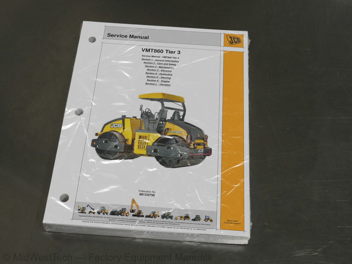
JCB Vibromax VMT860 Tier 3 Double Drum Roller Service Manual
238 pages · Publication 9813-0750
Added to your cart. View cart
- Models
- Vibromax VMT860 Tier 3 Double Drum
- Serial coverage
- from SN 1778003 onwards
- Manual type
- Service Manual
- Pages
- 238
- Publication
- 9813-0750
- Condition
- Brand new
What's inside
From the manual's own table of contents: 1 sections, 124 entries. See sample pages (PDF, 327 KB)
General104 topics
- About This Manual
- Machine Model and Serial Number
- Using the Service Manual
- Section Numbering
- Left Side, Right Side
- Cross References
- Identifying Your Machine
- Machine Identification Plate
- Zinc Plated Fasteners and Dacromet Fasteners
- Introduction
- Bolts and Screws
- Hydraulic Connections
- O' Ring Face Seal System
- Torque Stop' Hose System
- Numerical List
- Tool Detail Reference
- Section C - Electrics
- Section E - Hydraulics
- Sealing and Retaining Compounds
- Service Requirements
- Health and Safety
- Service Schedules
- Fluids, Lubricants and Capacities
- Tools
- Prepare the Machine for Maintenance
- Cleaning the Machine
- Check the Machine for Damage
- Access Panels
- Brakes
- Electrical System
- Engine
- Fuel System
- Hydraulic System
- Sprinkler System
- Drum
- Vibration System
- Using a Multimeter
- Measuring DC Voltage
- Measuring Resistance
- Measuring Continuity
- Measuring Frequency
- Testing a Diode or a Diode Wire
- Battery
- Maintenance
- Testing
- Specific Gravity Testing
- Wiring Harness Repair
- Repair Procedure
- Alternator
- General Description
- Service Precautions
- Charging Circuit Test
- Alternator Charging Test
- Starter Motor
- Starting Circuit Test
- Electrical Schematic
- Front Combination Lamp
- Instrument Panel
- Make the Machine Safe
- Hydraulic Contamination
- Hydraulic Fluid Quality
- Effects of Contamination
- Cleaning Operation
- Contaminant Standards
- Filters
- Quick Release Couplings
- Connecting and Disconnecting
- `Positional Type' Hydraulic Adaptors
- Fitting Procedure
- Removing and Replacing Components
- Description
- Service Procedures
- Replacing the Shaft Seal
- Changing the Seal of the Positioning Piston Cover
- Changing the Valve Seals
- Changing the Seals of the Pressure Cut-off
- Changing the Control Valve
- Changing the Auxiliary Pump
- Changing the Control Unit
- Pressure Testing
- Checking the Low Pressure (Charge Pressure)
- Checking the High Pressure
- Checking the Mechanical Zero Stroke
- Checking the Hydraulic Zero Stroke
- Introduction to Hydraulic Schematic Symbols
- General (Basic and Functional Symbols)
- Control Valves
- Example of Schematic Circuit
- Hydraulic Schematic VMT860
- Drive (Working Speed)
- Drive (Working Speed) Description
- Drive (High Speed)
- Drive (High Speed) Description
- Steering
- Steering Description
- Vibration
- Vibration Description
- Parking Brake
- Parking Brake Description
- Oil Cooler
- Oil Cooler Description
- Leakage
- Leakage Description
- Test Points
Section E - Hydraulics19 topics
- Drive System
- Hydraulic Travel System Fault Diagnosis Tables
- Vibration System Fault Diagnosis Table
- Removal and Replacement
- Removal
- Replacement
- Fault Finding
- Steering System Hydraulic Fault Diagnosis Tables
- Steering Hydraulic Pressure Testing
- Basic Engine Data
- Basic Operation
- Vibration Frequency
- Vibration Amplitude
- Diagnostics
- Measurement of Vibration System Performance
- Vibration System Hydraulic Fault Diagnosis Tables
- Dismantling and Assembly
- Dismantling
- Assembly
Inside this manual
Real pages from this service manual (238 pages). Open the sample pages (PDF, 327 KB)
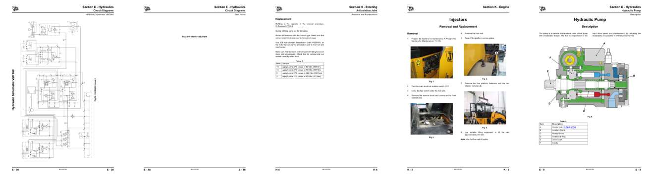
- Specifications, page 174: Circuit Diagrams
- Diagram, page 192: Circuit Diagrams
- Repair procedure, page 204: Section H - Steering
- Color page, page 213: Section K - Engine
- Color page, page 153: Section E - Hydraulics
This is a service manual
Here's how it compares to the other manual types.
Service manual
Factory repair procedures and technical information such as specifications, troubleshooting, and wiring and hydraulic diagrams, for the models and systems the manual covers. See What's inside for its topics.
Operator's manual
Safe operation, controls, maintenance schedules, lubrication points, inspections, and basic checks. Repair procedures are in the service manual.
Parts manual
Illustrated diagrams with factory part numbers for identifying components and ordering parts. Repair procedures are in the service manual.
Engine service manuals are sometimes sold separately, since certain machine models were offered with more than one engine option.
What it's used for
Factory manual for in-house farm and construction shop use. Straightforward, complete, and easy to follow. It contains the OEM information dealership service departments and parts counters use to diagnose problems, identify components, and perform maintenance or repairs correctly.
Service shops and owner/operators who repair their own equipment
Identifying correct parts and seeing how assemblies come apart and go back together
Keeping equipment running with less downtime
Factory manual, 238 pages
Quantity one is the manual described above.
Fast free USA shipping
Ships in 1 business day.
60-day returns
Free if the mistake is ours. A manual ordered in error must come back unopened in its shrink-wrap; you pay return shipping and a 20% restocking fee applies. Return policy
Other editions and similar models
Questions about model, serial number, engine coverage or contents? Contact us before purchasing and we'll help confirm it's the right manual. Please verify the manual type, machine model, serial number range and engine coverage before purchasing: manuals ordered in error carry a 20% restocking fee (return policy).