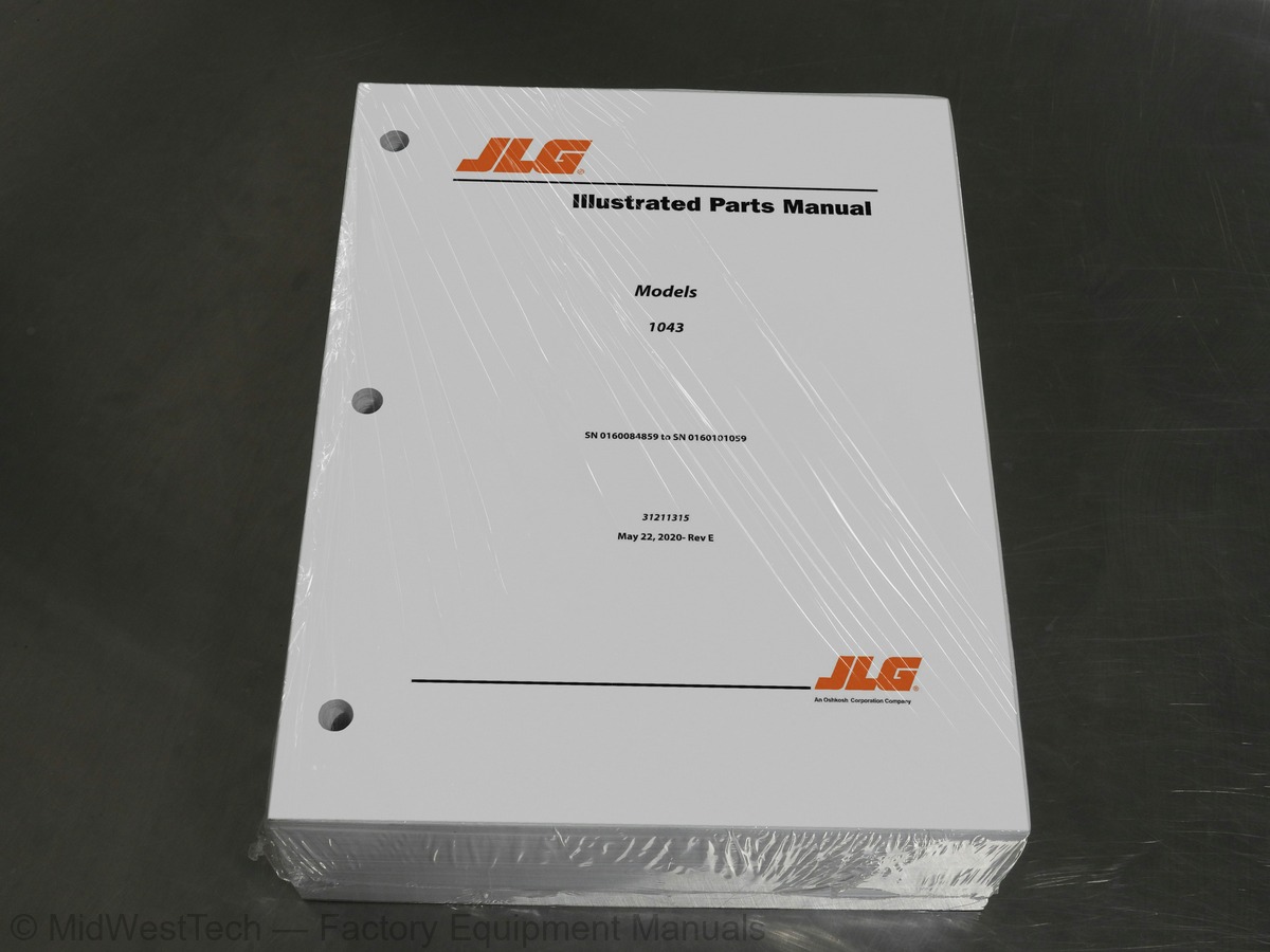
JLG 1043 Telehandler Parts Manual
1,028 pages · Publication 31211315
Added to your cart. View cart
- Models
- 1043
- Serial coverage
- Prior to 0160101059
- Manual type
- Parts Manual
- Pages
- 1,028
- Publication
- 31211315
- Condition
- Brand new
What's inside
From the manual's own table of contents: 211 sections, 452 entries. See sample pages (PDF, 556 KB)
General48 topics
- SECTION 1 - FRAME AND ATTACHING PARTS
- FIGURE 1-1. FRAME (OUTRIGGERS)
- FIGURE 1-2. ENGINE ENCLOSURE INSTALLATION
- FIGURE 1-3. ENGINE ENCLOSURE COVER INSTALLATION
- FIGURE 1-4. HOOD ASSEMBLY
- FIGURE 1-5. HOOD ASSEMBLY
- FIGURE 1-6. COVER INSTALLATION (OUTRIGGERS) (ULS)
- FIGURE 1-7. COVER INSTALLATION (OUTRIGGERS) (LS)
- FIGURE 1-8. COUNTERWEIGHT INSTALLATION
- FIGURE 1-9. TANK INSTALLATION
- FIGURE 1-10. FUEL TANK INSTALLATION
- FIGURE 1-11. HYDRAULIC TANK INSTALLATION
- FIGURE 1-12. FUEL CAP ASSEMBLY
- FIGURE 1-13. OUTRIGGERS INSTALLATION
- FIGURE 1-14. MIRROR INSTALLATION
- FIGURE 1-15. BOOM PROP INSTALLATION (ANSI)
- FIGURE 1-16. BOOM PROP BRACKET
- SECTION 2 - BOOM
- FIGURE 2-1. BOOM ASSEMBLY
- FIGURE 2-2. FIRST BOOM SECTION ASSEMBLY
- FIGURE 2-3. SECOND BOOM SECTION ASSEMBLY
- FIGURE 2-4. THIRD BOOM SECTION ASSEMBLY
- FIGURE 2-5. RETRACT CHAIN SHEAVE
- FIGURE 2-6. RETRACT CHAIN INSTALLATION
- FIGURE 2-7. EXTEND CHAIN INSTALLATION
- FIGURE 2-8. PINS INSTALLATION
- FIGURE 2-9. EXTEND CHAIN ROLLER
- FIGURE 2-10. HOSE BRACKET INSTALLATION
- FIGURE 2-11. BOOM PINNING INSTALLATION
- FIGURE 2-12. LIFT CYLINDER PINS INSTALLATION
- FIGURE 2-13. COMPENSATION CYLINDER PINS INSTALLATION
- FIGURE 2-14. BOOM PIVOT PIN INSTALLATION
- FIGURE 2-15. MANUAL QUICK COUPLER INSTALLATION
- FIGURE 2-16. HYDRAULIC QUICK COUPLER INSTALLATION
- FIGURE 2-17. BOOM PIN INSTALLATION
- FIGURE 2-18. TILT CYLINDER PIN INSTALLATION
- FIGURE 2-19. BOOM ANGLE INDICATOR INSTALLATION
- FIGURE 2-20. BOOM BRUSHES INSTALLATION
- FIGURE 2-21. QUICK COUPLER ASSEMBLY
- SECTION 3 - ATTACHMENTS
- FIGURE 3-1. CARRIAGE ASSEMBLY (1270MM)
- FIGURE 3-2. CARRIAGE ASSEMBLY (1524 MM)
- FIGURE 3-3. CARRIAGE ASSEMBLY (1829 MM)
- FIGURE 3-4. SIDE TILT CARRIAGE ASSEMBLY
- FIGURE 3-5. 90 SWING CARRIAGE ASSEMBLY (72 INCH)
- FIGURE 3-7. FORK POSITIONING CARRIAGE WITH FORKS (4.5 TON)
- FIGURE 3-16. FORK CLAMPS INSTALL
- FIGURE 3-18. FORK MOUNTED BUCKET (1.0 M³)
Show all 212 sections
FIGURE 4-35. EXHAUST INSTALLATION (ULS)63 topics
- FIGURE 4-36. EXHAUST INSTALLATION (LS)
- FIGURE 4-37. ENGINE PARTS INSTALLATION (NO HEATER)
- FIGURE 4-38. ENGINE PARTS INSTALLATION (HEATER)
- FIGURE 4-39. A/C PUMP INSTALLATION (ULS)
- FIGURE 4-40. A/C PUMP INSTALLATION (LS)
- FIGURE 4-41. FUEL TANK ASSEMBLY
- FIGURE 4-42. DEF TANK INSTALLATION
- FIGURE 4-45. DEF PUMP AND CONTROL INSTALLATION
- FIGURE 4-46. DEF PUMP LINES INSTALLATION
- FIGURE 4-47. MUFFLER INSTALLATION (LS)
- FIGURE 4-48. A/C LINES INSTALLATION
- FIGURE 4-49. HEATER BREATHER
- FIGURE 4-50. DEF BREATHER VALVE
- SECTION 5 - DRIVETRAIN
- FIGURE 5-1. DRIVETRAIN INSTALLATION
- FIGURE 5-2. FRONT AXLE INSTALLATION
- FIGURE 5-3. REAR AXLE INSTALLATION
- FIGURE 5-4. DRIVE SHAFTS INSTALLATION
- FIGURE 5-5. FRONT AXLE MOUNTING INSTALLATION
- FIGURE 5-6. FRONT AXLE LINES INSTALLATION
- FIGURE 5-7. REAR AXLE MOUNTING INSTALLATION
- FIGURE 5-8. REAR AXLE LINES INSTALLATION
- FIGURE 5-9. FRONT DRIVE SHAFT INSTALLATION
- FIGURE 5-10. REAR DRIVE SHAFT INSTALLATION
- FIGURE 5-11. FRONT AXLE
- FIGURE 5-12. FRONT AXLE, CENTRAL HOUSING
- FIGURE 5-13. FRONT AXLE, DIFFERENTIAL
- FIGURE 5-14. FRONT AXLE, HUB REDUCTION
- FIGURE 5-15. FRONT AXLE, BRAKES
- FIGURE 5-16. FRONT AXLE, STEERING
- FIGURE 5-17. FRONT AXLE, TRUNION
- FIGURE 5-18. FRONT AXLE, DIFFERENTIAL KIT
- FIGURE 5-19. FRONT AXLE, PLANET GEAR CARRIER
- FIGURE 5-20. FRONT AXLE, RING GEAR SUPPORT
- FIGURE 5-21. FRONT AXLE, PLANET GEAR CARRIER
- FIGURE 5-22. FRONT AXLE, SUPPORT
- FIGURE 5-23. FRONT AXLE, SUPPORT
- FIGURE 5-24. REAR AXLE
- FIGURE 5-25. REAR AXLE, BRAKES
- FIGURE 5-26. REAR AXLE, CENTRAL HOUSING
- FIGURE 5-27. REAR AXLE, DIFFERENTIAL
- FIGURE 5-28. REAR AXLE, HUB REDUCTION
- FIGURE 5-29. REAR AXLE, STEERING
- FIGURE 5-30. REAR AXLE, TRUNION
- FIGURE 5-31. REAR AXLE, DIFFERENTIAL KIT
- FIGURE 5-32. REAR AXLE, PLANET GEAR CARRIER
- FIGURE 5-33. REAR AXLE, PLANET GEAR CARRIER
- FIGURE 5-34. REAR AXLE, SUPPORT
- FIGURE 5-35. REAR AXLE, RING GEAR SUPPORT
- FIGURE 5-36. TRANSMISSION INSTALLATION
- FIGURE 5-37. POWERSHIFT TRANSMISSION
- FIGURE 5-38. TRANSMISION, ENGINE CONNECTION
- FIGURE 5-39. TRANSMISSION, CONVERTER
- FIGURE 5-40. TRANSMISSION, INPUT
- FIGURE 5-41. TRANSMISSION, HOUSING GROUP 1
- FIGURE 5-42. TRANSMISSION, HOUSING GROUP 2
- FIGURE 5-43. TRANSMISSION, CLUTCH GROUP 1
- FIGURE 5-44. TRANSMISSION, CLUTCH GROUP 2
- FIGURE 5-45. TRANSMISSION, COUPLING GROUP 1
- FIGURE 5-46. TRANSMISSION, COUPLING GROUP 2
- FIGURE 5-47. TRANSMISSION, COUPLING GROUP 3
- FIGURE 5-48. TRANSMISSION, COUPLING GROUP 4
- FIGURE 5-49. TRANSMISSION, OUTPUT
FIGURE 6-33. SEAT63 topics
- FIGURE 6-34. SEAT BELT INSTALLATION (3IN)
- FIGURE 6-35. SEAT BELT INSTALLATION
- FIGURE 6-36. HEATER INSTALLATION
- FIGURE 6-37. HEATER ASSEMBLY
- FIGURE 6-38. HEATER
- FIGURE 6-39. HEATER
- FIGURE 6-40. HEATER AND A/C INSTALLATION (CAB PARTS)
- FIGURE 6-41. HEATER AND A/C ASSEMBLY
- FIGURE 6-42. HEATER AND A/C
- FIGURE 6-43. HEATER AND A/C
- FIGURE 6-44. HVAC CAB ACTUATOR
- FIGURE 6-45. CAB CONDENSER ASSEMBLY
- FIGURE 6-46. A/C RECEIVER DRIER
- FIGURE 6-47. CONDENSER
- FIGURE 6-48. FRONT WIPER INSTALLATION
- FIGURE 6-49. REAR WIPER INSTALLATION
- FIGURE 6-50. ROOF WIPER INSTALLATION
- FIGURE 6-51. HEADLINER INSTALLATION
- FIGURE 6-52. OPEN CAB TRIM INSTALLATION
- FIGURE 6-53. ENCLOSED CAB TRIM INSTALLATION
- FIGURE 6-54. ROOF CAP INSTALLATION (A/C)
- FIGURE 6-55. ROOF CAP INSTALLATION (NO A/C)
- FIGURE 6-56. OPEN CAB FRONT COVER INSTALLATION
- FIGURE 6-57. ENCLOSED CAB FRONT COVER INSTALLATION
- FIGURE 6-58. NON SKID TAPE INSTALLATION
- FIGURE 6-59. EXTERNAL WINDOW RELEASE INSTALLATION (CAN & ISO)
- FIGURE 6-60. WASHER TANK INSTALLATION
- FIGURE 6-61. CAB GUARD INSTALLATION (TOP AND FRONT)
- FIGURE 6-62. CAB GUARD INSTALLATION (TOP)
- FIGURE 6-63. CAB GUARD INSTALLATION (FRONT)
- FIGURE 6-64. ROOF PIGTAIL CAP INSTALLATION
- FIGURE 6-65. ROOF PIGTAIL INSTALLATION
- FIGURE 6-66. RETRACTABLE SUNSCREEN INSTALLATION
- FIGURE 6-67. NO SUNSCREEN INSTALLATION
- SECTION 7 - CONTROLS
- FIGURE 7-1. BRAKE PEDAL INSTALLATION
- FIGURE 7-2. BRAKE PEDAL
- FIGURE 7-3. BRAKE PEDAL PLATE
- FIGURE 7-4. ACCELERATOR PEDAL INSTALLATION
- FIGURE 7-5. ACCELERATOR PEDAL
- FIGURE 7-6. STEERING COLUMN INSTALLATION
- FIGURE 7-7. EMERGENCY STEERING COLUMN INSTALLATION
- FIGURE 7-8. STEERING WHEEL INSTALLATION
- FIGURE 7-9. STEERING WHEEL
- FIGURE 7-10. HORN BUTTON INSTALLATION
- FIGURE 7-11. JOYSTICK INSTALLATION (2 ROLLER, 0 BUTTON)
- FIGURE 7-12. COLUMN CLAMP INSTALLATION
- FIGURE 7-13. WIPER-TURN SWITCH
- FIGURE 7-14. OUTRIGGER SWITCHES INSTALLATION
- FIGURE 7-15. JOYSTICK
- SECTION 8 - HYDRAULIC CIRCUITS
- FIGURE 8-1. MAIN HYDRAULIC INSTALLATION (OUTRIGGERS)
- FIGURE 8-2. PISTON PUMP INSTALLATION
- FIGURE 8-3. PISTON PUMP ASSEMBLY
- FIGURE 8-4. VALVE INSTALLATION (OUTRIGGERS)
- FIGURE 8-5. MAIN HYDRAULIC INSTALLATION
- FIGURE 8-6. FRAME LEVEL HYDRAULICS INSTALLATION (OUTRIGGERS)
- FIGURE 8-7. BOOM HYDRAULIC INSTALLATION
- FIGURE 8-8. CAB HYDRAULIC INSTALLATION
- FIGURE 8-9. MAIN HYDRAULIC INSTALLATION, SECONDARY STEERING (OUTRIGGERS)
- FIGURE 8-10. CAB HYDRAULIC INSTALLATION, EMERGENCY STEERING
- FIGURE 8-11. FRAME LEVEL INSTALLATION
- FIGURE 8-12. REAR AXLE STABILIZER INSTALLATION
FIGURE 10-1. MAIN ELECTRICAL INSTALLATION (ULS)67 topics
- FIGURE 10-2. MAIN ELECTRICAL INSTALLATION (ULS) (74 HP)
- FIGURE 10-3. MAIN ELECTRICAL INSTALLATION (LS)
- FIGURE 10-4. ELECTRICAL FRAME INSTALLATION
- FIGURE 10-5. POWER DISTRIBUTION ELECTRICAL BOX
- FIGURE 10-6. ENGINE BAY WIRING INSTALLATION (ULS)
- FIGURE 10-7. FRAME WIRING INSTALLATION (ULS)
- FIGURE 10-8. ENGINE BAY WIRING INSTALLATION (LS)
- FIGURE 10-9. FRAME WIRING INSTALLATION (ULS)
- FIGURE 10-10. FRAME WIRING INSTALLATION (LS)
- FIGURE 10-11. ENGINE BAY ELECTRICAL INSTALLATION
- FIGURE 10-12. ENGINE WIRING INSTALLATION (ULS)
- FIGURE 10-13. BOOM AUXILIARY ELECTRIC INSTALLATION
- FIGURE 10-14. BOOM AUXILIARY ELECTRIC HARNESS INSTALLATION
- FIGURE 10-15. BATTERY INSTALLATION
- FIGURE 10-16. ARCTIC COLD WEATHER PACKAGE INSTALLATION
- FIGURE 10-17. ARCTIC COLD WEATHER PACKAGE INSTALLATION (LS)
- FIGURE 10-18. FUEL FILTER HEATER INSTALLATION
- FIGURE 10-19. ARTIC BATTERIES INSTALLATION
- FIGURE 10-20. HYDRAULIC TANK HEATER INSTALLATION
- FIGURE 10-21. BACKUP ALARM INSTALLATION (120 DB)
- FIGURE 10-22. BACKUP ALARM INSTALLATION (97 DB)
- FIGURE 10-23. WHITE NOISE BACKUP ALARM INSTALLATION
- FIGURE 10-24. CAB ELECTRICAL INSTALLATION
- FIGURE 10-25. DASH ELECTRICAL INSTALLATION
- FIGURE 10-26. DASH ELECTRICAL INSTALLATION (LS)
- FIGURE 10-27. SWITCH LIGHT INSTALLATION
- FIGURE 10-28. USB CHARGER INSTALLATION
- FIGURE 10-29. OPEN CAB ELECTRICAL INSTALLATION WITH OPTIONS
- FIGURE 10-30. MULTIFUNCTION DISPLAY INSTALLATION
- FIGURE 10-31. ENCLOSED CAB ELECTRICAL INSTALLATION WITH OPTIONS
- FIGURE 10-32. REVERSE CAMERA INSTALLATION
- FIGURE 10-33. REVERSE CAMERA, NO HED
- FIGURE 10-34. REVERSE SENSOR INSTALLATION
- FIGURE 10-35. TELEMATICS READY INSTALLATION
- FIGURE 10-36. TELEMATICS CANBUS INSTALLATION (CLEARSKY 2) (ANSI)
- FIGURE 10-37. TELEMATICS CANBUS INSTALLATION (CLEARSKY 2) (C.E.)
- FIGURE 10-38. 4WARD TELEMATIC, HARNESS (CLEARSKY 2)
- FIGURE 10-39. CLEARSKY INSTALLATION 3-WIRE (ANSI)
- FIGURE 10-40. CLEARSKY INSTALLATION 3-WIRE (C.E.)
- FIGURE 10-41. ROAD LIGHTS INSTALLATION
- FIGURE 10-42. CAB WORKLIGHTS INSTALLATION (NO A/C)
- FIGURE 10-43. CAB WORKLIGHTS INSTALLATION (A/C)
- FIGURE 10-44. CAB WORKLIGHTS INSTALLATION (NO A/C - LED)
- FIGURE 10-45. CAB WORKLIGHTS INSTALLATION (A/C - LED)
- FIGURE 10-46. BOOM WORK LIGHTS INSTALLATION
- FIGURE 10-47. BOOM WORK LIGHTS INSTALLATION (LED)
- FIGURE 10-48. BEACON INSTALLATION
- FIGURE 10-49. BEACON INSTALLATION (LED)
- FIGURE 10-50. OUTRIGGER HARNESS
- FIGURE 10-51. RIDE CONTROL CB VALVE HARNESS INSTALLATION (LIFT)
- FIGURE 10-52. RIDE CONTROL CB VALVE HARNESS (LIFT)
- FIGURE 10-53. FRONT FRAME HARNESS
- FIGURE 10-54. REAR FRAME HARNESS
- FIGURE 10-55. ENGINE CHASSIS HARNESS (ULS)
- FIGURE 10-56. TBAP HARNESS
- FIGURE 10-57. BOOM ELECTRICAL HARNESS INSTALLATION
- FIGURE 10-58. BOOM HARNESS
- FIGURE 10-59. PLATFORM HARNESS
- FIGURE 10-60. CAB HARNESS
- FIGURE 10-61. FRONT FRAME HEADLIGHT HARNESS
- FIGURE 10-62. TAIL LIGHTS HARNESS
- FIGURE 10-63. BOOM WORKLIGHTS HARNESS
- FIGURE 10-64. BOOM LIGHTS INSTALLATION
- FIGURE 10-65. BOOM LED LIGHTS INSTALLATION
- FIGURE 10-66. A/C OPTION HARNESS
- FIGURE 10-67. REVERSE SENSOR HARNESS
- FIGURE 10-68. OPTION 1 CAB HARNESS
Inside this manual
Real pages from this parts manual (1,028 pages). Open the sample pages (PDF, 556 KB)
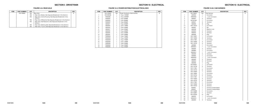
- Parts illustration, page 359: SECTION 5 - DRIVETRAIN
- Parts illustration, page 809: SECTION 10 - ELECTRICAL
- Parts illustration, page 929: SECTION 10 - ELECTRICAL
Other manuals for this machine
Save 10% on 2 manuals, 15% on 3 or more. Other manuals for the 1043 are listed below. Editions cover different serial number ranges: check the serial coverage and tick only the ones that match your machine.
Added to your cart. View cart
This is a parts manual
Here's how it compares to the other manual types.
Service manual
Factory repair procedures and technical information such as specifications, troubleshooting, and wiring and hydraulic diagrams, for the models and systems the manual covers. See What's inside for its topics.
Operator's manual
Safe operation, controls, maintenance schedules, lubrication points, inspections, and basic checks. Repair procedures are in the service manual.
Parts manual
Illustrated diagrams with factory part numbers for identifying components and ordering parts. Repair procedures are in the service manual.
What it's used for
Factory manual for in-house farm and construction shop use. Straightforward, complete, and easy to follow. It contains the OEM information dealership service departments and parts counters use to diagnose problems, identify components, and perform maintenance or repairs correctly.
Service shops and owner/operators who repair their own equipment
Identifying correct parts and seeing how assemblies come apart and go back together
Keeping equipment running with less downtime
Factory manual, 1,028 pages
Quantity one is the manual described above.
Fast free USA shipping
Ships in 1 business day.
60-day returns
Free if the mistake is ours. A manual ordered in error must come back unopened in its shrink-wrap; you pay return shipping and a 20% restocking fee applies. Return policy
Binder not included
Manuals over about 300 pages may need a standard 3-ring binder, which you can buy locally to keep the pages organized for shop use.
Other editions and similar models
Questions about model, serial number, engine coverage or contents? Contact us before purchasing and we'll help confirm it's the right manual. Please verify the manual type, machine model, serial number range and engine coverage before purchasing: manuals ordered in error carry a 20% restocking fee (return policy).