MidWestTechService, Parts and Operator's Manuals, in stock and ready to ship!
Fast free USA shippingShips in 1 business daySave 10% on 2 manuals, 15% on 3+

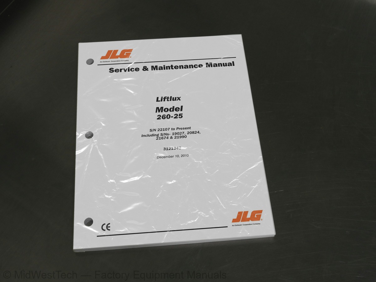
JLG 260-25 Scissor Lift Service Manual

168 pages · Publication 3121343

$69.93
Fast free USA shippingShips in 1 business daySave 10% on 2 manuals, 15% on 3 or morePay by credit or debit card or with PayPal. No PayPal account needed.
Models
260-25
Serial coverage
19027, 20824, 21674, 21990, 22107 to Present
Manual type
Service Manual
Pages
168
Publication
3121343
Condition
Brand new
JLG 260-25 Scissor Lift Service Manual, publication 3121343

What's inside

From the manual's own table of contents: 263 sections, 311 entries. See sample pages (PDF, 522 KB)

General
Hydraulic System Safety
Maintenance5 topics
  • Operating Specifications
  • Dimensional Data
  • Capacities
  • Tires
  • Engine
Battery2 topics
  • Torque Requirements
  • Limit Switches
Minimum Height Limit Switch
High Drive Speed Cutout Limit Switch
Maximum Drive Height Limit Switch
Maximum Height Limit Switch
Tilt Sensor
Outrigger Sensors
Oscillating Axle Limit Switch5 topics
  • Pressure Setting
  • Critical Stability Weights
  • Component Weights
  • Lubrication
  • Machine Preparation, Inspection, and Maintenance
Preparation, Inspection, and Maintenance
Pre-Start Inspection
Pre-Delivery Inspection and Frequent Inspection
Annual Machine Inspection
Preventative Maintenance1 topic
  • Service and Guidelines
Safety and Workmanship
Cleanliness
Components Removal and Installation
Component Disassembly and Reassembly
Pressure-Fit Parts
Bearings
Gaskets
Bolt Usage and Torque Application
Show all 263 sections
Hydraulic Lines and Electrical Wiring
Hydraulic System
Lubrication
Lubrication and Servicing1 topic
  • Lubrication and Information
Hydraulic Oil
Changing Hydraulic Oil
Lubrication Specifications2 topics
  • TABLE OF CONTENTS Operator Maintenance
  • Cylinder Drift Test
Platform Drift2 topics
  • Preventive Maintenance and Inspection Schedule
  • Operating Characteristics
Leveling Jacks1 topic
  • Wheel Assembly
Drive System
Torque Hub
Roll Test
Leak Test
Lubricant
Tire Replacement
Wheel Replacement
Wheel Installation1 topic
  • Drive Motor
Motor Disassembly
Motor Assembly2 topics
  • Steering Assembly
  • Rear Axle
Limit Switches2 topics
  • Outrigger Cylinder Removal
  • Engine Compartment
Hood Assembly
Deutz Engine
Engine Tray Slide
Hydraulic Pump Assembly
Hydraulic Pump
Exhaust Assembly
Air Filter Assembly
Engine Removal
Hydraulic Oil Tank
Pressure Filter4 topics
  • Fuel Tank
  • Ground Control Panel
  • Battery Removal
  • Platform
Platform Control Box
Joystick Controller
Receptacles
Main Platform Side Rails
Main Platform End Rails
Platform Extension Side Rails
Platform Extension End Rail
Platform Removal2 topics
  • Ladder Installation
  • Scissor Arms
Scissor Arm Assembly Removal
Lift Cylinder Removal
Scissor Arms Disassembly1 topic
  • Cylinders - Theory of Operation
Deck Extension Cylinder1 topic
  • TABLE OF CONTENTS Lift Cylinder
Outrigger Cylinders
Steer Cylinder1 topic
  • Valves - Theory of Operation
Solenoid Control Valves (Bang-Bang)
Relief Valves
Crossover Relief Valves
Proportional Valve2 topics
  • Cylinder Checking Procedure
  • Cylinder Repair
Disassembly
Cleaning and Inspection
Assembly1 topic
  • Valves
Valve Compartment
Main Valve Bank (Drive/Lift/Axle Lockout)
Drive Valve
Main Valve Bank (Extend/Outrigger)
Steer Valve
Hand Pump
Pressure Switch
Brake Valve
Manual Descent Valve Assembly
Lift/Lower Valve Block
Load Check Valves
Outrigger Safety Valves
Circulation Control Valve Block2 topics
  • Main Terminal Box Circuit Boards
  • Control Card Complex 2
General Description of Components and Functions1 topic
  • NIVOLUX - Automatic Self-Leveling System
Introduction
The System
Operation
NIVOLUX Board LED’s
Setting and Adjustment of the NIVOLUX Board1 topic
  • PNP5 Circuit Board
System
Adjustment1 topic
  • Trigger Control Circuit Card
Relay K1
Relay K2
Relay K31 topic
  • Limit Switch & Sensor Operation
Height Limit Switches
Tilt Switch
Oscillating Axle Limit Switches
Outrigger Limit Switches1 topic
  • Engine Control System (Circuit Board Code MC 536)
Functional Description1 topic
  • Load Sensing system (LSS)
LSS Re-Calibration Procedure2 topics
  • General
  • Multimeter Basics
Grounding
Backprobing
Min/Max
Polarity
Scale
Continuity Measurement Over Long Distances
Requirements
Procedure1 topic
  • Applying Silicone Dielectric Compound To Amp Connectors
Wedge Lock
Service - Voltage Reading1 topic
  • Working With Deutsch Connectors
DT/DTP Series Assembly
DT/DTP Series Disassembly
HD30/HDP20 Series Assembly
HD30/HDP20 Series Disassembly
Limit Switch Locations
Engine Operating Temperature Specifications
Torque Chart - (In/Lb - Ft/Lb). (For ASTM Fasteners)
Torque Chart (Metric Conversion) - (For ASTM Fasteners)
Torque Chart - (Nm) - (For Metric Class Fasteners)
Lubrication Diagram
Wheel Hub
Wheel Assembly Removal
Hub Torque Values
Drive Hub Assembly
Drive Motor Assembly
Steering Assembly
Outrigger Cylinder Removal - (Sheet 1 of 2)
Outrigger Cylinder Removal - (Sheet 2 of 2)
Hydraulic Oil Tank Removal
Pressure Filter Removal
Fuel Tank Removal
Ground Control Panel Removal
Battery Removal
Joystick
Receptacles Removal
Main Platform Side Rails Removal
Main Platform End Rails Removal
Extension Side Rail Removal
Extension End Rail Removal
Platform Removal - 1 of 2 (Front of Platform)
Platform Removal - 2 of 2 (Rear of Platform)
Ladder Installation
Limit Switch Adjustment
Scissor Arm Removal (Left Side)
Scissor Arm Removal (Right Side)
Lift Cylinder Valve Block Removal
Load Check Valve Romoval
Safety Valve and Limit Switch Removal
Cylinder Barrel Support
Cylinder Head Removal
Cylinder Rod Support
Piston Setscrew Removal
Piston Removal
Piston Seals
Spacer Removal
Cylinder Head Seals
Bushing Installation
Rod Seal Installation
Cylinder Head Seal Installation
Cylinder Head Installation
Spacer Installation
Piston Seal Installation
Piston Installation
Piston Setscrew Installation
Rod Installation
Valve Block Installation
Load Check Valve Installation
Safety Valve and Limit Switch Installation
Lifting Cylinder Assembly
Steering Cylinder Assembly
Outrigger Cylinder Assembly
Axle Lockout Cylinder Assembly
Extension Cylinder Assembly
Arms and Platform Positioning and Support
Valve/Hydraulic Compartment
Main Valve Pressure Setting
Platform Lower Flow Valve
Pressure Test Port
Main Valve Pressure Adjustment
Steer Valve Pressure Adjustment
Hand Pump Schematic
Hand Pump Assembly
Pressure Switch Adjustment
Brake Valve Adjustment
Manual Descent Valve
Main Terminal Box
Control Card Complex 2 Board
Nivolux Control Board
Voltage Measurement (DC)
Resistance Measurement
Continuity Measurement
Current Measurement (DC)
AMP Connector
Connector Assembly (1 of 4)
Connector Assembly (2 of 4)
Connector Assembly (3 of 4)
Connector Assembly (4 of 4)
Connector Disassembly
Connector Installation
DT/DTP Contact Installation
DT/DTP Contact Removal
HD/HDP Contact Installation
HD/HDP Locking Contacts Into Position
HD/HDP Contact Removal
HD/HDP Unlocking Contacts
Electrical Schematic - Sheet 1 of 18
Electrical Schematic - Sheet 2 of 18
Electrical Schematic - Sheet 3 of 18
Electrical Schematic - Sheet 4 of 18
Electrical Schematic - Sheet 5 of 18
Electrical Schematic - Sheet 6 of 18
Electrical Schematic - Sheet 7 of 18
Electrical Schematic - Sheet 8 of 18
Electrical Schematic - Sheet 9 of 18
Electrical Schematic - Sheet 10 of 18
Electrical Schematic - Sheet 11 of 18
Electrical Schematic - Sheet 12 of 18
Electrical Schematic - Sheet 13 of 18
Electrical Schematic - Sheet 14 of 18
Electrical Schematic - Sheet 15 of 18
Electrical Schematic - Sheet 16 of 18
Electrical Schematic - Sheet 17 of 18
Electrical Schematic - Sheet 18 of 18
Hydraulic Diagram - Sheet 1 of 2
Hydraulic Diagram - Sheet 2 of 2
Hydraulic Schematic - 1001092461 RevA
Operating Specifications
Dimensional Data
Capacities
Tire Specifications
Engine Specifications
Engine Battery Specifications
Pressure Settings
Critical Stability Weights
Component Weights
Mobil DTE 11M Specs
Inspection and Maintenance
Preventive Maintenance and Safety Inspection
Wheel Hub Technical Data
Drive Motor Specs
Tightening Torques
Engine Technical Data
Hydraulic Pump Specs
Joystick Specifications
Plug Loading Chart
J1 Connector
J2 Connector
J3 Connector
Complex 2 Circuit Board
NIVOLUX Circuit Board
PNP Circuit Board - I/O
Connector J1
Connector J2
Connector CON1
Trigger Control Circuit Board
Deutz Engine Control Board
LSS Load Height Chart
Main Terminal Box Wiring Description

Inside this manual

Real pages from this service manual (168 pages). Open the sample pages (PDF, 521 KB)

Sample pages from the JLG 260-25 Scissor Lift Service Manual: Specifications, Troubleshooting, Diagram
  • Specifications, page 13: SECTION 1 - SPECIFICATIONS
  • Troubleshooting, page 133: SECTION 6 - GENERAL ELECTRICAL INFORMATION & SCHEMATICS
  • Diagram, page 151: SECTION 6 - GENERAL ELECTRICAL INFORMATION & SCHEMATICS

This is a service manual

Here's how it compares to the other manual types.

This manual

Service manual

Factory repair procedures and technical information such as specifications, troubleshooting, and wiring and hydraulic diagrams, for the models and systems the manual covers. See What's inside for its topics.

Operator's manual

Safe operation, controls, maintenance schedules, lubrication points, inspections, and basic checks. Repair procedures are in the service manual.

Parts manual

Illustrated diagrams with factory part numbers for identifying components and ordering parts. Repair procedures are in the service manual.

Engine service manuals are sometimes sold separately, since certain machine models were offered with more than one engine option.

What it's used for

Factory manual for in-house farm and construction shop use. Straightforward, complete, and easy to follow. It contains the OEM information dealership service departments and parts counters use to diagnose problems, identify components, and perform maintenance or repairs correctly.

Service shops and owner/operators who repair their own equipment

Identifying correct parts and seeing how assemblies come apart and go back together

Keeping equipment running with less downtime

Factory manual, 168 pages

Quantity one is the manual described above.

Fast free USA shipping

Ships in 1 business day.

60-day returns

Free if the mistake is ours. A manual ordered in error must come back unopened in its shrink-wrap; you pay return shipping and a 20% restocking fee applies. Return policy

Other editions and similar models

Questions about model, serial number, engine coverage or contents? Contact us before purchasing and we'll help confirm it's the right manual. Please verify the manual type, machine model, serial number range and engine coverage before purchasing: manuals ordered in error carry a 20% restocking fee (return policy).