MidWestTechService, Parts and Operator's Manuals, in stock and ready to ship!
Fast free USA shippingShips in 1 business daySave 10% on 2 manuals, 15% on 3+

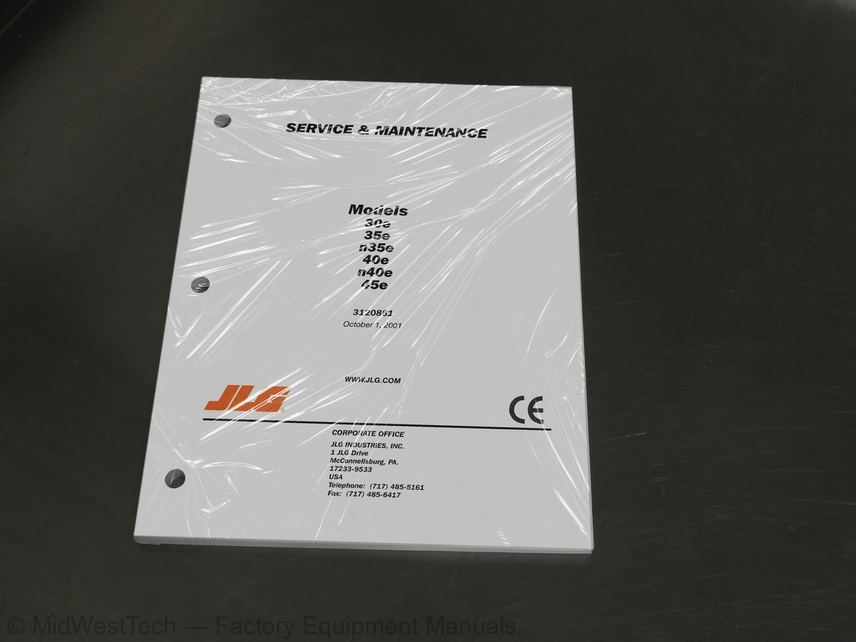
JLG 30e, 35e, 40e, 45e, n35e, n40e Boom Lift Service Manual

98 pages · Publication 3120861

$69.95
Fast free USA shippingShips in 1 business daySave 10% on 2 manuals, 15% on 3 or morePay by credit or debit card or with PayPal. No PayPal account needed.
Models
30e, 35e, 40e, 45e, n35e, n40e
Manual type
Service Manual
Pages
98
Publication
3120861
Condition
Brand new
JLG 30e, 35e, 40e, 45e, n35e, n40e Boom Lift Service Manual, publication 3120861

What's inside

From the manual's own table of contents: 81 sections, 117 entries. See sample pages (PDF, 542 KB)

IINTRODUCTION - MAINTENANCE SAFETY PRECAUTIONS
EFFECTIVITY CHANGES36 topics
  • CAPACITIES
  • COMPONENT DATA
  • PERFORMANCE DATA
  • TORQUE SPECIFICATIONS
  • LUBRICATION
  • PRESSURE SETTINGS
  • CYLINDER SPECIFICATIONS
  • MAJOR COMPONENT WEIGHTS
  • CRITICAL STABILITY WEIGHTS
  • SERIAL NUMBER LOCATIONS. (See Figure 1-3)
  • GENERAL
  • SERVICING AND MAINTENANCE GUIDELINES
  • LUBRICATION INFORMATION
  • CYLINDERS - THEORY OF OPERATION
  • VALVES - THEORY OF OPERATION
  • MOTOR CONTROLLER
  • WEAR PADS
  • BOOM MAINTENANCE
  • CYLINDER CHECKING PROCEDURES
  • CYLINDER REPAIR
  • CYLINDER REMOVAL AND INSTALLATION
  • TILT INDICATOR SWITCH LEVELING PROCEDURE. (If Equipped.)
  • BOOM LIMIT SWITCHES
  • POWER TRACK REMOVAL PROCEDURE (35/n35/40/n40/45 electric)
  • PRESSURE SETTING PROCEDURES. (In Sequence) (See Figure 2-29)
  • SWING BEARING
  • DRIVE TORQUE HUB. (See Figure 2-34)
  • DRIVE BRAKE ASSEMBLY
  • MID AND LOWER LIFT CYLINDER BLEEDING PROCEDURE. (40/n40/45 electric)
  • BOOM SYNCHRONIZING PROCEDURE. (40/n40/45 electric)
  • FREE WHEELING PROCEDURE
  • FOOTSWITCH ADJUSTMENT
  • AXLE DRAIN PLATES
  • PREVENTIVE MAINTENANCE AND INSPECTION SCHEDULE
  • TROUBLESHOOTING INFORMATION
  • HYDRAULIC CIRCUIT CHECKS
Torque Chart
Lubrication Chart - 30 electric. (Sheet 1 of 6)
Lubrication Chart - 30 electric. (Sheet 2 of 6)
Lubrication Chart - 35/n35 electric. (Sheet 3 of 6)
Lubrication Chart - 35/n35 electric. (Sheet 4 of 6)
Lubrication Chart - 40/n40/45 electric. (Sheet 5 of 6)
Lubrication Chart - 40/n40/45 electric. (Sheet 6 of 6)
Serial Number Locations - 30 electric. (Sheet 1 of 3)
Serial Number Locations - 35/n35 electric. (Sheet 2 of 3)
Serial Number Locations - 40/n40/45 electric. (Sheet 3 of 3)
Sevcon Controller Troubleshooting Flow Charts. (Sheet 1 of 4)
Sevcon Controller Troubleshooting Flow Charts. (Sheet 2 of 4)
Sevcon Controller Troubleshooting Flow Charts. (Sheet 3 of 4)
Sevcon Controller Troubleshooting Flow Charts. (Sheet 4 of 4)
Location and Thickness of Wear Pads
Locations of Components - Platform Support (Model 30)
Location of Components - Removal of Base Boom. (Model 30)
Location of Components - Platform Support. (Models 35/n35/40/n40/45)
Location of Components - Slave Leveling Cylinder
Location of Components - Removal of Base Boom. (Models 35/n35/40/n40/45)
Location of Components - Aft End of Fly Boom Wear Pad Adjustments
Location of Components - Removal of Telescope Cyllinder
Show all 81 sections
Location of Components - Front Base Boom Wear Pad Adjustments
Boom Prop Configurations - 30 electric. (Sheet 1 of 3)
Boom Prop Configurations - 35/n35 electric. (Sheet 2 of 3)
Boom Prop Configurations - 35/n35 electric. (Sheet 3 of 3)
Removal of Cylinder Retainer
Removal of Set Screws
Removal of Seals and O-Rings
Removal of Piston Seals
Rod Seal Installation
Wiper Seal Installation
Poly-Pak Piston Seal Installation
O"-Ring Installation
Piston Seal Kit Installation
Steer Cylinder Piston Installation
Installing Retainer Ring on Telescope Cylinder Barrel
Lift Cylinder Assembly
Upper Boom Lift Cylinder Removal
Mid Boom Lift Cylinder Removal
Lower Boom Lift Cyllinder Removal
Upper Telescope Cylinder Removal
Tilt Switch
Pressure Setting Procedures - 30 electric. (Sheet 1 of 3)
Pressure Setting Procedures - 35/n35 electric. (Sheet 2 of 3)
Pressure Setting Procedures - 40/n40/45 electric. (Sheet 3 of 3)
Swing Bearing Feeler Gauge Check
Swing Bearing Tolerance Boom Placement - 30/35/n35 electric
Swing Bearing Tolerance Boom Placement - 40/n40/45 electric
Swing Bearing Tolerance Measuring Point
Swing Bearing Torquing Sequence
Port "P" Location
Synchronizing Valve
Upright Leveling
Drive Brake Release
Drive Axle Drain Plate
Electrical Schematic 30 electric. (Sheet 1 of 4)
Electrical Schematic 30 electric. (Sheet 2 of 4)
Electrical Schematic 30 electric. (Sheet 3 of 4)
Electrical Schematic 30 electric. (Sheet 4 of 4)
Electrical Schematic 35/40/45 electric. (Sheet 1 of 4)
Electrical Schematic. 35/40/45 electric. (Sheet 2 of 4)
Electrical Schematic. 35/40/45 electric. (Sheet 3 of 4)
Electrical Schematic. 35/40/45 electric. (Sheet 4 of 4)
Hydraulic Diagram - 30 electric
Hydraulic Diagram - 35 electric
Hydraulic Diagram - 40/45 electric
Hydraulic Oil
Lubrication Specifications
Cylinder Specifications
Cylinder Piston Nut Torque Specifications
Holding Valve Torque Specifications
PREVENTIVE MAINTENANCE AND INSPECTION SCHEDULE
PLATFORM ASSEMBLY - TROUBLESHOOTING
BOOM ASSEMBLY - TROUBLESHOOTING
TURNTABLE ASSEMBLY - TROUBLESHOOTING
CHASSIS ASSEMBLY - TROUBLESHOOTING
HYDRAULIC SYSTEM - TROUBLESHOOTING
ELECTRICAL SYSTEM - TROUBLESHOOTING

Inside this manual

Real pages from this service manual (98 pages). Open the sample pages (PDF, 542 KB)
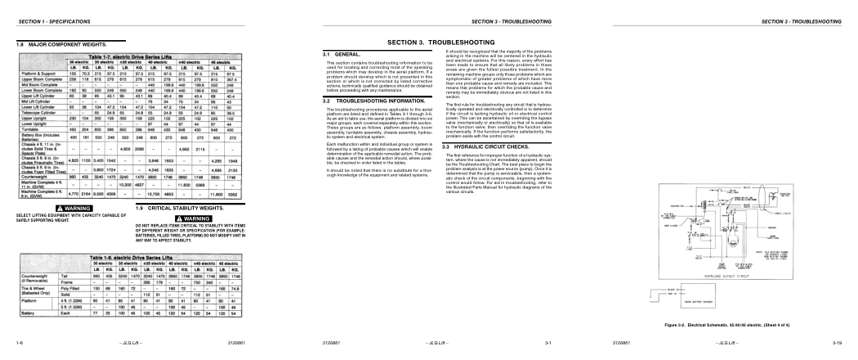
Sample pages from the JLG 30e, 35e, 40e, 45e, n35e, n40e Boom Lift Service Manual: Specifications, Troubleshooting, Diagram
  • Specifications, page 14: SECTION 1 - SPECIFICATIONS
  • Troubleshooting, page 75: SECTION 3 - TROUBLESHOOTING
  • Diagram, page 93: SECTION 3 - TROUBLESHOOTING

Other manuals for this machine

Save 10% on 2 manuals, 15% on 3 or more. Other manuals for the 30e, 35e, 40e, 45e, n35e, n40e are listed below. Editions cover different serial number ranges: check the serial coverage and tick only the ones that match your machine.

This manual: Service Manual 3120861$69.95
Other manuals for the 30e, 35e, 40e, 45e, n35e, n40e

Parts manuals

Details
Details

This is a service manual

Here's how it compares to the other manual types.

This manual

Service manual

Factory repair procedures and technical information such as specifications, troubleshooting, and wiring and hydraulic diagrams, for the models and systems the manual covers. See What's inside for its topics.

Operator's manual

Safe operation, controls, maintenance schedules, lubrication points, inspections, and basic checks. Repair procedures are in the service manual.

Parts manual

Illustrated diagrams with factory part numbers for identifying components and ordering parts. Repair procedures are in the service manual.

Engine service manuals are sometimes sold separately, since certain machine models were offered with more than one engine option.

What it's used for

Factory manual for in-house farm and construction shop use. Straightforward, complete, and easy to follow. It contains the OEM information dealership service departments and parts counters use to diagnose problems, identify components, and perform maintenance or repairs correctly.

Service shops and owner/operators who repair their own equipment

Identifying correct parts and seeing how assemblies come apart and go back together

Keeping equipment running with less downtime

Factory manual, 98 pages

Quantity one is the manual described above.

Fast free USA shipping

Ships in 1 business day.

60-day returns

Free if the mistake is ours. A manual ordered in error must come back unopened in its shrink-wrap; you pay return shipping and a 20% restocking fee applies. Return policy

Other editions and similar models

Questions about model, serial number, engine coverage or contents? Contact us before purchasing and we'll help confirm it's the right manual. Please verify the manual type, machine model, serial number range and engine coverage before purchasing: manuals ordered in error carry a 20% restocking fee (return policy).