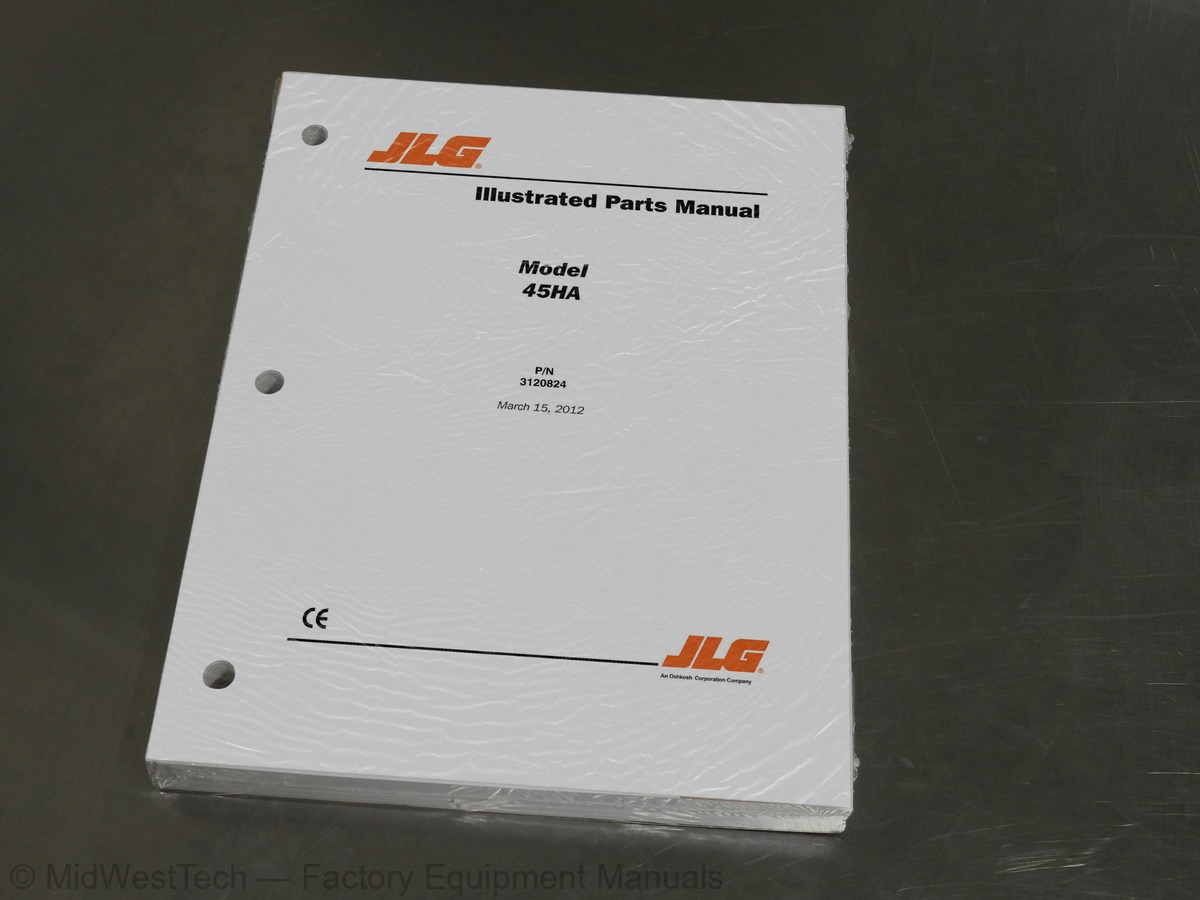
JLG 45HA Boom Lift Parts Manual
283 pages · Publication 3120824
Added to your cart. View cart
- Models
- 45HA
- Manual type
- Parts Manual
- Pages
- 283
- Publication
- 3120824
- Condition
- Brand new
What's inside
From the manual's own table of contents: 38 sections, 95 entries. See sample pages (PDF, 457 KB)
General57 topics
- SECTION 1 - FRAME
- FIGURE 1-1. FRAME AND STEERING INSTALLATION - 5FT-9IN/1.75M 2WD FRAME (WITH SINGLE ROD CYLINDER)
- FIGURE 1-2. FRAME AND STEERING INSTALLATION - 6FT-6IN/2M 2WD FRAME (WITH DOUBLE ROD CYLINDER)
- FIGURE 1-3. FRAME AND STEERING INSTALLATION 6FT-6IN/2M 4WD FRAME
- FIGURE 1-4. TIRE AND WHEEL DRIVE INSTALLATIONS
- FIGURE 1-5. DRIVE HUB ASSEMBLIES
- FIGURE 1-6. DRIVE HUB/BRAKE ASSEMBLIES
- FIGURE 1-7. DRIVE BRAKE ASSEMBLY - AUSCO
- FIGURE 1-8. DRIVE BRAKE ASSEMBLY - MICO
- FIGURE 1-9. DRIVE MOTOR ASSEMBLY - 2WD
- FIGURE 1-10. DRIVE MOTOR ASSEMBLY - 4WD
- FIGURE 1-11. VALVES INSTALLATION (FRAME MOUNTED)
- FIGURE 1-12. TOW PACKAGE INSTALLATION
- SECTION 2 - TURNTABLE
- FIGURE 2-1. CONTROL VALVES INSTALLATIONS - VICKERS (FORD GAS AND DEUTZ DIESEL)
- FIGURE 2-2. CONTROL VALVES INSTALLATIONS - VICKERS (ELECTRIC MACHINES)
- FIGURE 2-3. ACCESSORY VALVE ASSEMBLY
- FIGURE 2-4. VALVE ASSEMBLY - FPS (STEER)
- FIGURE 2-5. CONTROL VALVE ASSEMBLY (VICKERS) (PRIOR TO OCTOBER 1994)
- FIGURE 2-6. CONTROL VALVE ASSEMBLY - (VICKERS) (OCTOBER 1994 TO PRESENT)
- FIGURE 2-7. VALVE ASSEMBLY - SINGLE STACK BANG-BANG
- FIGURE 2-8. VALVE ASSEMBLY - FPS
- FIGURE 2-9. TURNTABLE, BEARING AND SWING DRIVE INSTALLATION
- FIGURE 2-10. SWING BRAKE ASSEMBLY
- FIGURE 2-11. SWING MOTOR ASSEMBLY
- FIGURE 2-12. FORD ENGINE INSTALLATION - WITH DISTRIBUTORLESS IGNITION SYSTEM
- FIGURE 2-13. DUAL FUEL INSTALLATION (FORD DISTRIBUTORLESS IGNITION)
- FIGURE 2-14. GENERATOR INSTALLATION - 110V (FORD) (OPTIONAL)
- FIGURE 2-15. DEUTZ ENGINE INSTALLATION
- FIGURE 2-16. GENERATOR INSTALLATION 110 VOLT (DEUTZ) (OPTIONAL)
- FIGURE 2-17. PUMP ASSEMBLY - BARNES (FORD AND DEUTZ POWERED MACHINES)
- FIGURE 2-18. ELECTRIC POWERED MACHINES COMPONENTS INSTALLATION
- FIGURE 2-19. PUMP ASSEMBLY - BARNES (ELECTRIC POWERED MACHINES)
- FIGURE 2-20. BATTERY CHARGER ASSEMBLY (ELECTRIC POWERED MACHINE)
- FIGURE 2-21. TANKS INSTALLATION
- FIGURE 2-22. ROTARY OIL COUPLING INSTALLATION
- FIGURE 2-23. OPTIONAL MANUAL DESCENT INSTALLATION
- FIGURE 2-24. GROUND CONTROL BOX INSTALLATION (GAS/DIESEL MACHINES)
- FIGURE 2-25. GROUND CONTROL BOX INSTALLATION (ELECTRIC MACHINES)
- FIGURE 2-26. TILT INDICATOR, LIGHTS AND ALARMS INSTALLATIONS (TURNTABLE MOUNTED)
- FIGURE 2-27. HOODS INSTALLATION (GAS/DIESEL MACHINES BUILT THROUGH 1992)
- FIGURE 2-28. HOODS INSTALLATION (GAS/DIESEL MACHINES BUILT 1993 TO PRESENT)
- FIGURE 2-29. HOODS INSTALLATION (ELECTRIC MACHINES)
- SECTION 3 - BOOM
- FIGURE 3-1. BOOMS AND LIMIT SWITCHES INSTALLATIONS
- FIGURE 3-2. MAIN BOOM ASSEMBLY
- FIGURE 3-3. TOWER BOOM ASSEMBLIES
- FIGURE 3-4. BOOM WIPERS INSTALLATION
- SECTION 4 - PLATFORM
- FIGURE 4-1. STANDARD PLATFORM AND FOOTSWITCH INSTALLATION
- FIGURE 4-2. LOW MOUNT PLATFORM AND FOOTSWITCH INSTALLATIONS
- FIGURE 4-3. ROTATOR MOTOR ASSEMBLY
- FIGURE 4-4. CONSOLE BOX ASSEMBLY (ELECTRIC MACHINES)
- FIGURE 4-5. CONSOLE BOX ASSEMBLY (GAS, DIESEL AND DUAL FUEL MACHINES PRIOR TO JANUARY 1993)
- FIGURE 4-6. CONSOLE BOX ASSEMBLY (GAS, DIESEL AND DUAL FUEL MACHINES JANUARY 1993 TO PRESENT)
- FIGURE 4-7. OPTIONAL COMMON PLATFORM MOUNTED COMPONENTS
- SECTION 5 - CYLINDER
Show all 39 sections
Inside this manual
Real pages from this parts manual (283 pages). Open the sample pages (PDF, 457 KB)
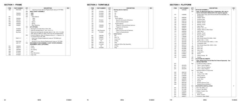
- Parts illustration, page 26: SECTION 1 - FRAME
- Parts illustration, page 70: Working Section Options:
- Parts illustration, page 170: SECTION 4 - PLATFORM
Other manuals for this machine
Save 10% on 2 manuals, 15% on 3 or more. Other manuals for the 45HA are listed below. Editions cover different serial number ranges: check the serial coverage and tick only the ones that match your machine.
Added to your cart. View cart
This is a parts manual
Here's how it compares to the other manual types.
Service manual
Factory repair procedures and technical information such as specifications, troubleshooting, and wiring and hydraulic diagrams, for the models and systems the manual covers. See What's inside for its topics.
Operator's manual
Safe operation, controls, maintenance schedules, lubrication points, inspections, and basic checks. Repair procedures are in the service manual.
Parts manual
Illustrated diagrams with factory part numbers for identifying components and ordering parts. Repair procedures are in the service manual.
What it's used for
Factory manual for in-house farm and construction shop use. Straightforward, complete, and easy to follow. It contains the OEM information dealership service departments and parts counters use to diagnose problems, identify components, and perform maintenance or repairs correctly.
Service shops and owner/operators who repair their own equipment
Identifying correct parts and seeing how assemblies come apart and go back together
Keeping equipment running with less downtime
Factory manual, 283 pages
Quantity one is the manual described above.
Fast free USA shipping
Ships in 1 business day.
60-day returns
Free if the mistake is ours. A manual ordered in error must come back unopened in its shrink-wrap; you pay return shipping and a 20% restocking fee applies. Return policy
Other editions and similar models
Questions about model, serial number, engine coverage or contents? Contact us before purchasing and we'll help confirm it's the right manual. Please verify the manual type, machine model, serial number range and engine coverage before purchasing: manuals ordered in error carry a 20% restocking fee (return policy).