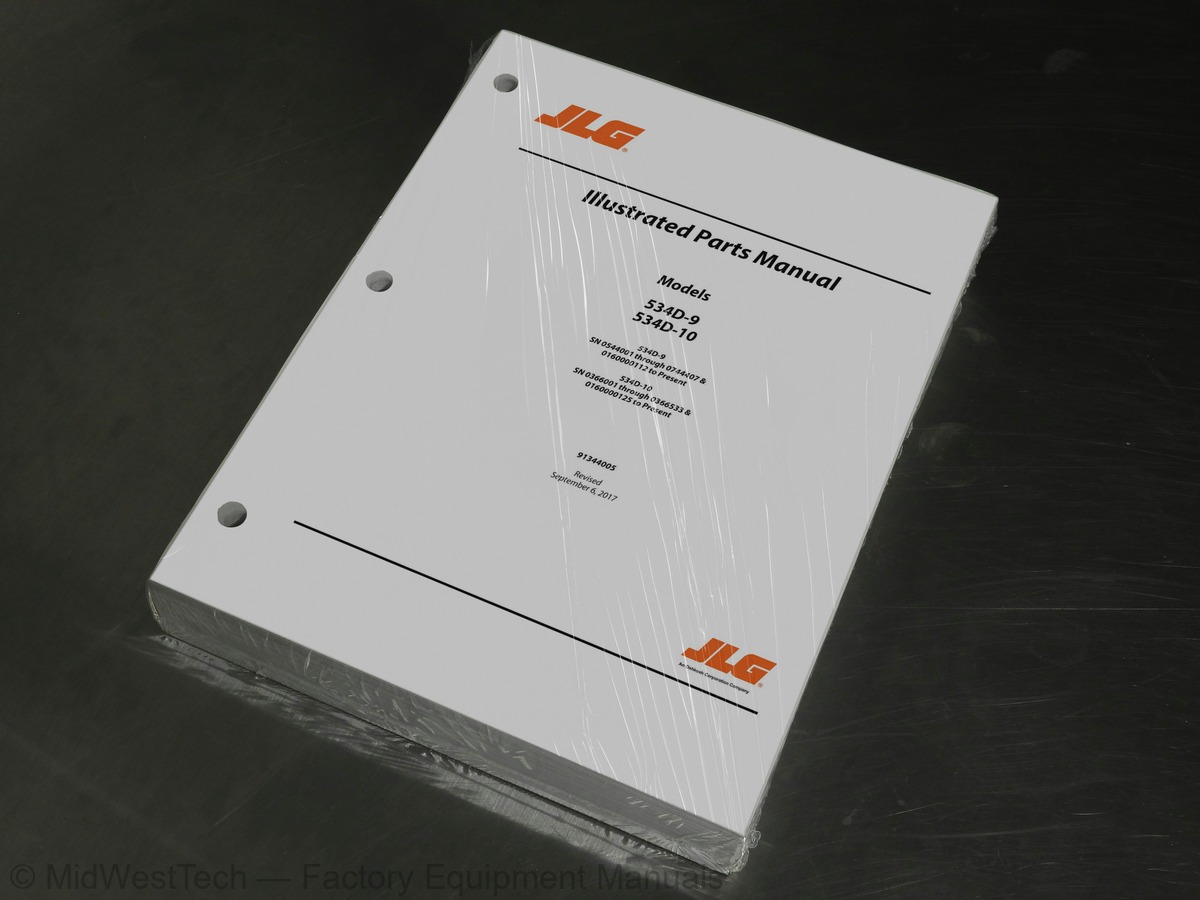
JLG 534D-10, 534D-9 Telehandler Parts Manual
848 pages · Publication 91344005
Added to your cart. View cart
- Models
- 534D-10, 534D-9
- Serial coverage
- 534D-10:0160000125 to Present, 534D-10:0366001-0366533, 534D-9:0160000112, 534D-9:0544001-0744407
- Manual type
- Parts Manual
- Pages
- 848
- Publication
- 91344005
- Condition
- Brand new
What's inside
From the manual's own table of contents: 12 sections, 82 entries. See sample pages (PDF, 656 KB)
SECTION 2 - BOOM14 topics
- FIGURE 2-9. BOOM CROSS SECTION/PUSH BEAM PIN - 40 FT & 45 FT BOOM
- FIGURE 3-1. BUCKETS
- FIGURE 3-12. QUICK HOOK ASSEMBLY
- FIGURE 3-13. FORK MOUNTED LIFTING HOOK (PRIOR TO SN 2005134-01)
- FIGURE 3-14. FORK MOUNTED LIFTING HOOK (SN 2005134-01 TO PRESENT)
- FIGURE 3-23. FORKS
- FIGURE 3-24. PERSONNEL PLATFORM
- FIGURE 3-25. FORK MOUNTED PLATFORM
- FIGURE 4-23. ENGINE PUMP MOUNT AND FLYWHEEL HOUSING (534D-9 SN 0544001 through 0544084)
- FIGURE 4-24. ENGINE PUMP MOUNT AND FLYWHEEL HOUSING (534D-9 SN 0544085 through 0544216)
- FIGURE 4-25. ENGINE PUMP MOUNT AND FLYWHEEL HOUSING (534D-9 SN 0544217 through 0544717)
- FIGURE 4-28. ENGINE PUMP MOUNT AND FLYWHEEL HOUSING (534D-10 SN 0366001 through 0366016)
- FIGURE 4-29. ENGINE PUMP MOUNT AND FLYWHEEL HOUSING (534D-10 SN 0366017 through 0366053)
- FIGURE 4-30. ENGINE PUMP MOUNT AND FLYWHEEL HOUSING (534D-10 SN 0366054 through 0366187)
SECTION 5 - DRIVE TRAIN1 topic
- FIGURE 5-4. LEFT AND RIGHT HOUSING AND AXLE AND WHEEL FLANGE ASSEMBLIES - ROCKWELL (534D-9 SN 0544001 through 0160000446
SECTION 6 - CAB3 topics
- FIGURE 6-8. DASH PANEL ASSEMBLY
- FIGURE 6-11. WINDSHIELD/TOP WINDOW KIT INSTALLATION
- FIGURE 6-12. SKYLIGHT WIPER INSTALLATION
SECTION 7 - CONTROLS3 topics
- FIGURE 7-6. STEERING COLUMN AND ATTACHING PARTS
- FIGURE 7-7. CAB RIGHT SIDE CONTROLS
- FIGURE 7-8. JOYSTICK ASSEMBLY
SECTION 8 - HYDRAULIC CIRCUITS5 topics
- FIGURE 8-7. FRONT DRIVE CIRCUIT
- FIGURE 8-11. INCHING AND PARKING BRAKE LINES
- FIGURE 8-12. LIFT CYLINDER
- FIGURE 8-13. CROWD CYLINDER
- FIGURE 8-20. JOYSTICK CIRCUIT
SECTION 9 - HYDRAULIC COMPONENTS19 topics
- FIGURE 9-16. THERMAL BYPASS VALVE ASSEMBLY
- FIGURE 9-19. OUTRIGGER CYLINDER FOR SERVICE ONLY
- FIGURE 9-20. FLOW DIVIDER ASSEMBLY
- FIGURE 9-24. SOLENOID VALVE
- FIGURE 9-25. SWAY CYLINDER VALVE
- FIGURE 9-31. HYDRAULIC RESERVOIR AND FILTERS
- FIGURE 9-32. FRONT DRIVE MOTOR
- FIGURE 9-33. MAIN HYDRAULIC PUMP
- FIGURE 9-36. TRACTION LOCK VALVE
- FIGURE 9-37. REAR DRIVE MOTOR
- FIGURE 9-40. CROSSOVER VALVE
- FIGURE 9-41. OUTRIGGER VALVE - 534D-10
- FIGURE 9-43. OPTIONAL STABILIZER VALVE ASSEMBLY (534D-9 SN 0544010 to Present; 534D-10 SN 0366234 to Present)
- FIGURE 9-46. QUICK START CYLINDER AND VALVE ASSEMBLY
- FIGURE 9-47. 180, SWING CARRIAGE CYLINDER
- FIGURE 9-48. 72 IN 90, SWING CARRIAGE CYLINDER
- FIGURE 9-49. SIDE TILT CARRIAGE CYLINDER
- FIGURE 9-50. SIDE TILT CARRIAGE CYLINDER
- FIGURE 9-51. GRAPPLE BUCKET CYLINDER
SECTION 10 - ELECTRICAL2 topics
- FIGURE 10-9. AUXILIARY ELECTRICAL INSTALLATION (SN 0160027771 to Present)
- FIGURE 10-10. AUXILIARY ELECTRICAL HARNESSES (SN 0160027771 to Present)
SECTION 12 - OPTIONS22 topics
- FIGURE 12-1. AUXILIARY HYDRAULIC W/ELECTRONIC ASSEMBLY (Prior to SN 0160027771)
- FIGURE 12-8. AUXILIARY HYDRAULICS AND SWAY ASSEMBLY - 40 IN BOOM (534D-9 Prior to SN 0644119; 534D-10 Prior to SN 036608
- FIGURE 12-11. HYDRAULIC RESERVOIR HEATER INSTALLATION
- FIGURE 12-12. TILT ON JOYSTICK INSTALLATION
- FIGURE 12-13. OVERHEAD WINDOW
- FIGURE 12-21. DUAL P.O. CHECK VALVE
- FIGURE 12-23. SWING VALVE ASSEMBLY
- FIGURE 12-24. SWAY CYLINDER
- FIGURE 12-31. LH TILT/SWAY ASSEMBLY (Prior to SN 0160027771)
- FIGURE 12-33. AUXILIARY HYDRAULICS AND SWAY ASSEMBLY - 45 FT BOOM (Prior to SN 0160027771)
- FIGURE 12-34. AUX HYDRAULIC W/ELECTRICS ASSEMBLY - 45 FT BOOM (Prior to SN 0160027771)
- FIGURE 12-37. AUXILIARY HYD ELECTRONICS W/LH TILT/SWAY ASSEMBLY - 45 FT BOOM (Prior to SN 0160027771) .. 776 FIGURE 12-3
- FIGURE 12-39. RH AUXILIARY HYDRAULIC ASSEMBLY - 45 FT BOOM (Prior to SN 0160027771)
- FIGURE 12-40. REAR AXLE STABILIZER FIELD KIT
- FIGURE 12-41. 5-BUTTON AUXILIARY HANDLE ASSEMBLY (Prior to SN 0160027771)
- FIGURE 12-43. WINCH INSTALLATION - 45 FT BOOM (SN 0160027771 to Present)
- FIGURE 12-44. AUXILIARY HYD ELECTRONICS W/LH TILT/SWAY (Prior to SN 0160027771)
- FIGURE 12-45. ADJUSTABLE TILT ON JOYSTICK
- FIGURE 12-46. FUEL/WATER SEPARATOR INSTALLATION
- FIGURE 12-49. CAB REPLACEMENT SERVICE KIT
- FIGURE 12-51. PINTLE HOOK INSTALLATION
- FIGURE 12-52. COLD START INSTALLATION (SN 0160001166 to Present)
SECTION 13 - RECOMMENDED SPARE PARTS1 topic
- FIGURE 13-1. RECOMMENDED SPARE PARTS
Inside this manual
Real pages from this parts manual (848 pages). Open the sample pages (PDF, 655 KB)
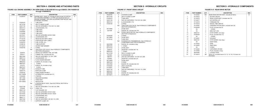
- Parts illustration, page 231: SECTION 4 - ENGINE AND ATTACHING PARTS
- Parts illustration, page 439: SECTION 8 - HYDRAULIC CIRCUITS
- Parts illustration, page 569: SECTION 9 - HYDRAULIC COMPONENTS
This is a parts manual
Here's how it compares to the other manual types.
Service manual
Factory repair procedures and technical information such as specifications, troubleshooting, and wiring and hydraulic diagrams, for the models and systems the manual covers. See What's inside for its topics.
Operator's manual
Safe operation, controls, maintenance schedules, lubrication points, inspections, and basic checks. Repair procedures are in the service manual.
Parts manual
Illustrated diagrams with factory part numbers for identifying components and ordering parts. Repair procedures are in the service manual.
What it's used for
Factory manual for in-house farm and construction shop use. Straightforward, complete, and easy to follow. It contains the OEM information dealership service departments and parts counters use to diagnose problems, identify components, and perform maintenance or repairs correctly.
Service shops and owner/operators who repair their own equipment
Identifying correct parts and seeing how assemblies come apart and go back together
Keeping equipment running with less downtime
Factory manual, 848 pages
Quantity one is the manual described above.
Fast free USA shipping
Ships in 1 business day.
60-day returns
Free if the mistake is ours. A manual ordered in error must come back unopened in its shrink-wrap; you pay return shipping and a 20% restocking fee applies. Return policy
Binder not included
Manuals over about 300 pages may need a standard 3-ring binder, which you can buy locally to keep the pages organized for shop use.
Questions about model, serial number, engine coverage or contents? Contact us before purchasing and we'll help confirm it's the right manual. Please verify the manual type, machine model, serial number range and engine coverage before purchasing: manuals ordered in error carry a 20% restocking fee (return policy).