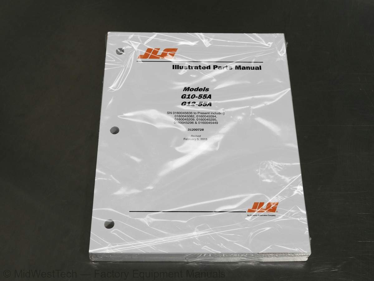
JLG G10-55A, G12-55A Telehandler Parts Manual
418 pages · Publication 31200728
Added to your cart. View cart
What's inside
From the manual's own table of contents: 49 sections, 156 entries. See sample pages (PDF, 649 KB)
General53 topics
- SECTION 1 - FRAME AND ATTACHING PARTS
- FIGURE 1-1. FRAME AND ATTACHING PARTS
- FIGURE 1-2. COVERS
- FIGURE 1-3. OUTRIGGER INSTALLATION
- FIGURE 1-4. PINTLE HOOK
- SECTION 2 - BOOM
- FIGURE 2-1. BOOM INSTALLATION
- FIGURE 2-2. FIRST BOOM SECTION
- FIGURE 2-3. FIRST BOOM SECTION
- FIGURE 2-4. SECOND BOOM SECTION
- FIGURE 2-5. SECOND BOOM SECTION
- FIGURE 2-6. THIRD BOOM SECTION
- FIGURE 2-7. THIRD BOOM SECTION
- FIGURE 2-8. FOURTH BOOM SECTION
- FIGURE 2-9. FOURTH BOOM SECTION
- FIGURE 2-10. EXTEND CHAINS
- FIGURE 2-11. EXTEND CHAINS
- FIGURE 2-12. RETRACT CHAINS
- FIGURE 2-13. RETRACT CHAINS
- FIGURE 2-14. MANUAL QUICK ATTACH
- SECTION 3 - ATTACHMENTS
- FIGURE 3-1. STANDARD CARRIAGE (Prior to SN 0160052000)
- FIGURE 3-2. STANDARD CARRIAGE (SN 0160052000 to Present)
- FIGURE 3-3. SIDE TILT CARRIAGE
- FIGURE 3-4. 50 IN SIDE SHIFT CARRIAGE
- FIGURE 3-5. DUAL FORK POSITIONING CARRIAGE
- FIGURE 3-6. 90, SWING CARRIAGE
- FIGURE 3-7. 180, SWING CARRIAGE
- FIGURE 3-8. SHEET HANDLER CARRIAGE
- FIGURE 3-9. FORKS AND ATTACHING PARTS
- FIGURE 3-10. FORK MOUNTED PLATFORM
- FIGURE 3-11. FORK MOUNTED HOOK
- FIGURE 3-12. GENERAL PURPOSE BUCKET
- FIGURE 3-13. GRAPPLE BUCKET
- FIGURE 3-14. TRUSS BOOM
- FIGURE 3-15. TRUSS BOOM WITH WINCH
- FIGURE 3-16. 8 FOOT STANDARD MAST
- FIGURE 3-17. 8 FT SIDE TILT ELECTRIC MAST
- SECTION 4 - ENGINE AND ATTACHING PARTS
- FIGURE 4-1. ENGINE INSTALLATION
- FIGURE 4-2. ENGINE
- FIGURE 4-3. ENGINE
- FIGURE 4-4. FUEL TANK AND LINES
- FIGURE 4-5. RADIATOR INSTALLATION
- FIGURE 4-6. AIR CLEANER INSTALLATION
- FIGURE 4-7. AIR CLEANER INSTALLATION
- FIGURE 4-8. EXHAUST INSTALLATION
- FIGURE 4-9. EXHAUST INSTALLATION
- SECTION 5 - DRIVE TRAIN
- FIGURE 5-1. DRIVETRAIN COMPONENTS (Prior to SN 0160054609)
- FIGURE 5-2. DRIVETRAIN COMPONENTS (SN 0160054609 to Present)
- FIGURE 5-3. FRONT AXLE
- FIGURE 5-6. FRONT AXLE - DIFFERENTIAL
Show all 50 sections
FIGURE 8-11. BOOM HYDRAULIC ASSEMBLY54 topics
- FIGURE 8-12. AUXILIARY HYDRAULIC CIRCUIT
- FIGURE 8-13. FRAME LEVEL CIRCUIT
- FIGURE 8-14. OUTRIGGER CIRCUIT
- SECTION 9 - HYDRAULIC COMPONENTS
- FIGURE 9-1. LIFT CYLINDER AND HARDWARE
- FIGURE 9-2. EXTEND/RETRACT CYLINDER AND HARDWARE
- FIGURE 9-3. TILT CYLINDER AND HARDWARE
- FIGURE 9-4. COMPENSATION CYLINDER AND HARDWARE
- FIGURE 9-5. FRAME LEVEL CYLINDER AND HARDWARE
- FIGURE 9-6. OUTRIGGER CYLINDER AND HARDWARE
- FIGURE 9-7. STABILIZER CYLINDER AND HARDWARE
- FIGURE 9-8. SIDE TILT CARRIAGE CYLINDER (Prior to SN 0160066379)
- FIGURE 9-9. SIDE TILT CARRIAGE CYLINDER (SN 0160066379 to Present)
- FIGURE 9-10. 50 IN SIDE SHIFT CARRIAGE CYLINDER
- FIGURE 9-11. SWING CARRIAGE CYLINDER
- FIGURE 9-12. GRAPPLE BUCKET CYLINDER
- FIGURE 9-13. MAIN CONTROL VALVE
- FIGURE 9-14. PISTON PUMP
- FIGURE 9-15. HYDRAULIC TANK
- FIGURE 9-16. STEER SELECT VALVE
- FIGURE 9-17. BRAKE VALVE
- FIGURE 9-18. HYDRAULIC MANIFOLD VALVE
- FIGURE 9-19. DECOMPRESSION VALVE
- SECTION 10 - ELECTRICAL
- FIGURE 10-1. ENGINE COMPARTMENT ELECTRICAL INSTALLATION
- FIGURE 10-2. ENGINE COMPARTMENT ELECTRICAL INSTALLATION
- FIGURE 10-3. ARCTIC PACKAGE INSTALLATION
- FIGURE 10-4. BOOM AND FRAME ELECTRICAL INSTALLATION
- FIGURE 10-5. CAB ELECTRICAL INSTALLATION
- FIGURE 10-6. CAB SWITCHES
- FIGURE 10-7. CLEARSKY INSTALLATION
- FIGURE 10-8. WORK LIGHTS
- FIGURE 10-9. DRIVE LIGHTS
- FIGURE 10-10. ENGINE HARNESS
- FIGURE 10-11. ENGINE HARNESS
- FIGURE 10-12. TRANSMISSION HARNESS
- FIGURE 10-13. FRAME HARNESS
- FIGURE 10-14. VEC OPTIONS HARNESS
- FIGURE 10-15. TRANSMISSION RELAY HARNESS
- FIGURE 10-16. ENCLOSED CAB OPTIONS HARNESS
- FIGURE 10-17. DASH HARNESS
- FIGURE 10-18. INSTRUMENT PANEL HARNESS
- FIGURE 10-19. FRAME ROAD LIGHT HARNESS
- FIGURE 10-20. BOOM WORK LIGHT HARNESS
- FIGURE 10-21. CAB ROAD LIGHT HARNESS
- FIGURE 10-22. CAB WORK LIGHT HARNESS
- FIGURE 10-23. A/C HARNESS
- FIGURE 10-24. VEC HARNESS
- SECTION 11 - DECALS
- FIGURE 11-1. CAB AND FRAME DECALS
- FIGURE 11-2. BOOM DECALS
- SECTION 12 - RECOMMENDED SPARE PARTS
- FIGURE 12-1. RECOMMENDED SPARE PARTS
- PART NUMBER INDEX
Inside this manual
Real pages from this parts manual (418 pages). Open the sample pages (PDF, 648 KB)

- Parts illustration, page 133: SECTION 5 - DRIVE TRAIN
- Parts illustration, page 253: SECTION 8 - HYDRAULIC CIRCUITS
- Parts illustration, page 337: SECTION 10 - ELECTRICAL
Other manuals for this machine
Save 10% on 2 manuals, 15% on 3 or more. Other manuals for the G10-55A, G12-55A are listed below. Editions cover different serial number ranges: check the serial coverage and tick only the ones that match your machine.
Added to your cart. View cart
This is a parts manual
Here's how it compares to the other manual types.
Service manual
Factory repair procedures and technical information such as specifications, troubleshooting, and wiring and hydraulic diagrams, for the models and systems the manual covers. See What's inside for its topics.
Operator's manual
Safe operation, controls, maintenance schedules, lubrication points, inspections, and basic checks. Repair procedures are in the service manual.
Parts manual
Illustrated diagrams with factory part numbers for identifying components and ordering parts. Repair procedures are in the service manual.
What it's used for
Factory manual for in-house farm and construction shop use. Straightforward, complete, and easy to follow. It contains the OEM information dealership service departments and parts counters use to diagnose problems, identify components, and perform maintenance or repairs correctly.
Service shops and owner/operators who repair their own equipment
Identifying correct parts and seeing how assemblies come apart and go back together
Keeping equipment running with less downtime
Factory manual, 418 pages
Quantity one is the manual described above.
Fast free USA shipping
Ships in 1 business day.
60-day returns
Free if the mistake is ours. A manual ordered in error must come back unopened in its shrink-wrap; you pay return shipping and a 20% restocking fee applies. Return policy
Binder not included
Manuals over about 300 pages may need a standard 3-ring binder, which you can buy locally to keep the pages organized for shop use.
Other editions and similar models
Questions about model, serial number, engine coverage or contents? Contact us before purchasing and we'll help confirm it's the right manual. Please verify the manual type, machine model, serial number range and engine coverage before purchasing: manuals ordered in error carry a 20% restocking fee (return policy).