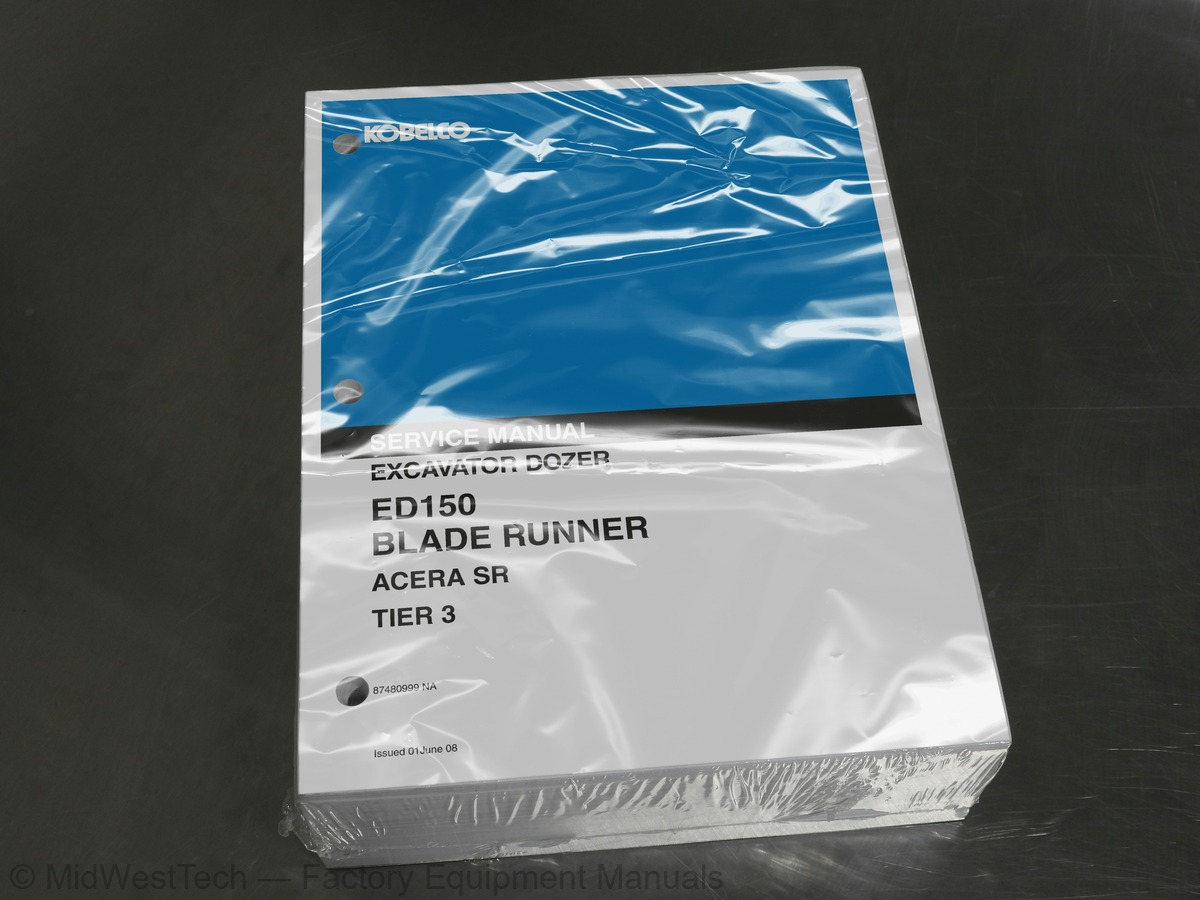
Kobelco ED150 Blade Runner Acera SR Tier 3 Excavator Dozer Service Manual
1,096 pages · Publication 87480999
Added to your cart. View cart
- Models
- ED150 Blade Runner Acera SR Tier 3
- Manual type
- Service Manual
- Pages
- 1,096
- Publication
- 87480999
- Condition
- Brand new
What's inside
From the manual's own table of contents: 9 sections, 416 entries. See sample pages (PDF, 528 KB)
ED150 BLADE RUNNER ACERA SR SERVICE MANUAL1 topic
- Section Table of Contents
SECTION 1 - SAFETY AND GENERAL INFORMATION36 topics
- GENERAL PRECAUTIONS FOR MAKING REPAIRS
- Preparation Before Disassembling
- Safety When Disassembling And Assembling
- Disassembling and Assembling Hydraulic Equipment
- Removing Hydraulic Equipment Assembly
- Disassembling Hydraulic Equipment
- Inspecting Parts
- Assembling Hydraulic Equipment
- Installing Hydraulic Equipment
- Electrical Equipment
- Hydraulic Parts
- Weld Repair
- Environmental Issues
- INTERNATIONAL UNIT SYSTEM
- Introduction
- SPECIFICATIONS
- Components
- General Dimensions
- Transportation
- Lifting
- Crawlers
- Type of Bucket
- Dozer Specifications
- Engine Specifications
- Engine Characteristic Curve
- ATTACHMENT DIMENSIONS
- Boom
- Boom Dimensional Drawing
- Boom Maintenance Standard
- Arm Dimensional Drawing
- Arm Maintenance Standard
- Bucket
- Bucket Dimensional Drawing
- Bucket Dimensional Table
- Lug Section Dimensional Drawing
- Boss Section Dimensional Drawing
SECTION 2 - MAINTENANCE58 topics
- TIGHTENING TORQUES FOR CAPSCREWS AND NUTS
- SCREW SIZE
- Capscrew (Bolt)
- Capscrew (Socket Bolt)
- Socket Set Screw
- TIGHTENING TORQUE FOR HOSE AND FITTING
- Joint (O-ring Type)
- Hydraulic Hose (30° Flare Type)
- Joint (ORS Type)
- Split Flange
- TIGHTENING TORQUES FOR NUTS AND SLEEVES
- PLUGS
- Plug For Hydraulic Pipe Joint
- Plug For Hydraulic Equipment
- SPECIAL SPANNER FOR TUBE
- SPECIAL TOOLS
- APPLICATION OF SCREW LOCKING COMPOUND AND SEALING COMPOUND
- SUCTION STOPPER
- Dimensions
- COUNTERWEIGHT LIFTING JIG
- TOOL FOR PULLING OUT OF BOOM MOUNTING PIN
- Slide Hammer For Boom Foot Pin
- UPPER FRAME LIFTING JIG
- Upper Frame Lifting Jig (1/2)
- Upper Frame Lifting Jig (2/2)
- ENGINE MOUNTING PEDESTAL
- Engine Stand
- TRACK SPRING SET JIG
- MAINTENANCE STANDARD AND TEST PROCEDURE
- How To Use the Maintenance Standard and Cautions to be Exercised
- Performance Inspection Standard Table
- Measurement of Engine Speed
- Measurement of Hydraulic Pressure
- Preparing to Measure Hydraulic Pressure
- Place to Install Pressure Gauge
- Pressure Adjustment Position
- Procedure for Adjusting Relief Valve
- Measuring Travel Performances
- Travel Speed
- Deviation of Travel
- Performances of Parking Brake
- Drain Rate of Travel Motor
- Measuring Swing Performances
- Swing Speed
- Performance of Swing Brake
- Performance of Swing Parking Brake
- Drain Rate of Swing Motor
- Measuring Attachment Operating Performances
- Operating Time of Cylinders
- Oil Tightness of Cylinders
- Measuring Performances of Swing Bearing
- MECHATRO CONTROLLER
- Engine Control Input / Output
- Adjustment of Mechatro Controller Output (B-c Adjustment)
- Purpose of the Adjustment
- In Cases Where the Adjustment of Mechatro Controller is Required
- Preparation
- Adjusting Procedure
SECTION 3 - SYSTEMS41 topics
- MECHATRO CONTROL SYSTEM
- Preface
- Summary Of Mechatro Control System
- Mechatro Control System In General
- Unload Valve Control
- Positive Control and P-Q Control
- Boom Up Conflux Control
- Arm-In Recirculation and Conflux Control
- Arm-In Anti-cavitation Control
- Arm-Out Conflux Control
- Bucket Digging (Dump) Control
- Swing Priority Control
- Travel Straight Control
- Pressure Release Control (Include Extra Pressure Release)
- N&B Switch Control (Option)
- Option Conflux Control
- N&B Solenoid Relief Valve Control
- Summary of Multi Display
- Gauge Cluster
- KPSS Work Mode Switch
- Procedure of Setting a Flow Rate and a Option Relief Pressure at A/B Mode
- Pump Flow Rate and Relief Pressure Selection (A Mode/ B Mode)
- Maintenance Screen Displays
- Gauge Cluster Display
- Self Diagnosis Display
- Service Diagnosis Display Function
- Service Diagnosis Display Screen Operating Procedure
- Service Diagnosis Display Screen (Example)
- Service diagnosis data list
- Trouble History Diagnosis
- How to Display
- How to Delete Contents of Trouble History
- Trouble Diagnosis Mode
- Set Procedure of Maintenance Schedule
- Adjusting Procedure of Display
- Mechatro Control Equipment
- C-1 Mechatro Controller
- Gauge Cluster (Symbol C-2)
- Relay and Fuse Box (Symbol E-1)
- High Pressure Sensor
- Low Pressure Sensor
CHAPTER 1 - MECHATRO CONTROL SYSTEM135 topics
- COMMUNICATION OFF
- HYDRAULIC SYSTEM
- Summary
- Hydraulic Circuits and Components
- Standard
- N&B Specification (Option)
- Boom & Arm Safety Specification
- Color Coding Standard For Hydraulic Circuits
- Neutral Circuit
- Operation of Bypass Cut Valve and Unloading Valve Housed In Control Valve
- Safety Lock Lever and Pilot Circuit
- Pump Positive Flow Control
- Pump P-Q Curve Control Operation
- Travel Circuit
- Travel Forward Pilot Simultaneous Operation Circuit
- 2-speed Travel Solenoid Command Circuit and Auto 1st Speed Return Function
- Travel Main Circuit
- Travel Motor Function
- Bucket Circuit
- Pilot Circuit For Bucket Digging
- Auto Acceleration Operation
- Stand-By Current Constant Control
- Boom Circuit
- Boom Raise Pilot Circuit
- Boom Up 2 Pumps Conflux Main Circuit In C/V
- Boom Down Pilot Circuit
- Prevention Of Natural Fall By Lock Valve and Actuation at Lowering
- Constant Recirculation Function of Boom Down Main Circuit
- Swing Circuit
- Pilot Circuit For Left Swing
- Swing Auto Parking Brake
- Swing Main Circuit
- Swing Motor Circuit
- Pilot Line Air Bleeding Circuit
- Arm In, Light-Load Operating Pilot Circuit
- Arm In, Light-Load Variable Normal Recirculation, Internal Conflux Main Circuit
- Arm In, Heavy Load Operating Pilot Circuit
- Arm In, Heavy Load Operating Recirculation Cut Main Circuit
- Arm Out Pilot Circuit
- Arm Out 2 Pumps Conflux Main Circuit
- Natural Fall Protection With Arm Lock Valve
- Combined Circuit
- Boom Up / Travel, Pilot Circuit
- Boom Up / Travel, Main Circuit
- Swing / Arm In Light Load, Pilot Circuit
- Swing / Arm In, Swing Priority Main Circuit
- Pressure Draining (Releasing) Circuit
- Pressure Relieving Pilot Circuit
- How To Switch To PRESSURE RELEASE MODE
- Pressure Release Main Circuit
- Dozer
- ELECTRIC CIRCUIT DIAGRAMS
- Electrical Equipment List
- Harness
- Harness List
- Instrument Panel Assembly
- Controller Install
- Operator's Control (Switch Install)
- Upper Electric Assembly
- Upper Harness Assembly (1/8)
- Upper Harness Assembly (2/8)
- Upper Harness Assembly (3/8)
- Upper Harness Assembly (4/8)
- Upper Harness Assembly (5/8)
- Upper Harness Assembly (6/8)
- Upper Harness Assembly (7/8)
- Upper Harness Assembly (8/8)
- Upper Harness (1/5)
- Upper Harness (2/5)
- Upper Harness (3/5)
- Upper Harness (4/5)
- Upper Harness (5/5)
- Battery Cable
- Battery Grounding Cable
- Battery Relay Cable
- Starter Motor Cable
- ECU Harness
- Floor Ground Cable
- Harness for Over Load Alarm
- Upper Harness Assembly (Floor) (1/4)
- Upper Harness Assembly (Floor) (2/4)
- Upper Harness Assembly (Floor) (3/4)
- Upper Harness Assembly (Floor Plate) (4/4)
- Floor Harness (1/3)
- Floor Harness (2/3)
- Floor Harness (3/3)
- Floor Grounding Cable
- Cab Sub Harness
- Tuner Harness
- Engine Harness Assembly
- Engine Sub Cable
- Cab Install
- Cab Assembly
- Cab Harness Assembly
- Cab Harness (1/2)
- Cab Harness (2/2)
- Key Switch Ground Harness
- Boom Harness Assembly
- Boom Harness
- Boom Light Install
- Upper Light Install
- Engine Room Light Install
- HYDRAULIC COMPONENTS
- Hydraulic Pump - Regulator
- Hydraulic Pump
- Construction
- Operation
- Regulator
- Adjusting the Regulator
- Causes of Fault Resulting From Regulator
- Control Curve of Pump
- Control Valve
- Outside View
- Ports
- Construction and Operation
- Hydraulic Circuit Diagram
- Cartridge Type Solenoid Proportional Relief Valve for N&B
- Installation of Cartridge Type Solenoid Proportional Relief Valve
- Air Breathing
- Pilot Valve (ATT)
- Outline
- Pilot Valve (Travel)
- Swing Motor Unit
- Specification
- Operation of Hydraulic Motor
- Valve Casing Section
- Operation of Brake Section
- Swing Reduction Unit
- Travel Motor
- Makeup Of Travel Motor
- Functions of Travel Motor
- Functional Principle of Reduction Gear
- Swivel Joint
- General View
- Cylinder
CHAPTER 5 - AIR CONDITIONING SYSTEM28 topics
- BASIC SYSTEM OF AIR CONDITIONER (HVAC AIR CONDITIONER)
- Air Cycle
- Auto Air Conditioner System Outline
- Component and Construction
- Component
- Piping
- Air Conditioner
- Air Dryer Assembly
- Function
- Mechanism of Cooling Circuit
- Cooling Circuit
- Component Parts
- Disassembly and Assembly
- Precautions to be Exercised in Operation
- Disassembly and Assembly of Unit
- Charging Refrigerant
- Operating Procedure
- Charging Procedure
- Vacuum Making Operation
- Gas Charging Operation
- Electric Circuit
- Wiring Diagram and Connectors
- Structure and Operation of Each Functional Parts and the Inspection
- Troubleshooting
- Self Diagnosis Function On Display Of Panel
- Position of Indication for Failure
- Explanation of Indication for Failure
- Explanation of Monitor Mode
SECTION 4 - DISASSEMBLY AND ASSEMBLY81 topics
- ATTACHMENTS
- REMOVING AND INSTALLING
- Attachment Assembly
- Removing Bucket
- Attaching Bucket
- Procedure For Adjusting Clearance
- Removing Arm
- Attaching Arm
- Preparation for Removing and Attaching Boom
- Removing Boom
- Attaching Boom
- Dozer Blade
- Dozer Blade Removal
- Dozer Blade Installation
- DISASSEMBLING AND ASSEMBLING
- Preparation Before Disassembly
- Construction of Cylinder (General Example of Cylinder)
- Disassembly
- Removing Rod Cover and Piston Rod
- Removing Piston Assembly
- Disassembling Piston
- Disassembling Rod Cover
- Removing Pin Bushing
- Removing Check Valve (Arm Cylinder Only)
- Cleaning
- Assembling Pin Bushing
- Assembling of Piston
- Assembling Rod Cover
- Inserting Rod Cover To Piston Rod
- Assembling Piston Onto Piston Rod
- Overall Assembly
- Inspection After Assembly
- Maintenance Standards
- Inspection After Disassembly
- Limit of Serviceability
- Tightening Torque
- Volume of Oil Leak
- Tools and Jigs List
- Allen Wrench and Spanner Wrench
- Dust Seal Pressing Jig (For Rod Cover)
- Eye Wrench (For Piston Nut)
- Wrench (For Piston)
- Rod Cover Fixing Jig
- Piston (Slipper) Seal Fixing Jig
- Piston Seal Holding-Down Jig
- UPPER STRUCTURE
- Operator Seat
- Removal
- Installation
- Battery
- Removing
- Guard
- Preparation For Removal
- Remove Guard
- Under Cover
- Fuel Tank
- Hydraulic Tank
- Air Cleaner
- Muffler
- Counterweight
- Radiator and Oil Cooler
- Procedure of Disassembling and Assembling the Radiator/inter Cooler Core
- Engine
- Preparation For Removing
- TRAVEL SYSTEM
- Crawler
- Removing Crawler
- Installing
- Maintenance Standard
- Jigs
- Upper Roller
- Upper Roller Assembly
- Lower Roller
- Lower Roller Assembly
- Front Idler (Idler Adjuster Assembly)
- Front Idler Assembly
- Idler Assembly
- Idler Adjuster Assembly
- Sprocket
- Swing Bearing
- Swing Bearing Assembly
SECTION 5 - TROUBLESHOOTING14 topics
- TROUBLESHOOTING OUTLINE
- Judgment of Actual Equipment at Site
- Get to the Site as Quickly as Possible
- Verify Background of Trouble Occurred
- How to Diagnose Trouble
- Explanation of the Cause of Trouble
- Classification of Failure and Troubleshooting
- The Blown Fuse of Mechatro Controller
- Troubleshooting By Error Code
- TROUBLESHOOTING (BY TROUBLE)
- Electric Systems
- Wiring Checking Procedure
- Trouble
- Engine Related Troubleshooting
GENERAL CONTENTS13 topics
- Tips on disassembling and reassembling
- List of tightening torque
- Testing compression pressure
- Disassembling and inspection crankcase, crankshaft and piston
- Inspecting and repairing piston, connecting rod, crankshaft and crankcase
- Reassembling cylinder head and valve mechanism
- Installing fuel system
- Installing lubrication system
- Installing cooling system
- Installing inlet and exhaust system
- Installing electrical system
- Performance test (JIS standard)
- Inspecting wiring
Inside this manual
Real pages from this service manual (1,096 pages). Open the sample pages (PDF, 527 KB)

- Diagram, page 270: CHAPTER 3 - ELECTRIC SYSTEM
- Specifications, page 382: CHAPTER 4 - COMPONENTS SYSTEM
- Troubleshooting, page 798: CHAPTER 1 - TROUBLESHOOTING BY ERROR CODES
- Color page, page 571: Issued 06-2008
- Color page, page 893: INTRODUCTION
- Foldout diagram (color): Issued 06-2008
This is a service manual
Here's how it compares to the other manual types.
Service manual
Factory repair procedures and technical information such as specifications, troubleshooting, and wiring and hydraulic diagrams, for the models and systems the manual covers. See What's inside for its topics.
Operator's manual
Safe operation, controls, maintenance schedules, lubrication points, inspections, and basic checks. Repair procedures are in the service manual.
Parts manual
Illustrated diagrams with factory part numbers for identifying components and ordering parts. Repair procedures are in the service manual.
Engine service manuals are sometimes sold separately, since certain machine models were offered with more than one engine option.
What it's used for
Factory manual for in-house farm and construction shop use. Straightforward, complete, and easy to follow. It contains the OEM information dealership service departments and parts counters use to diagnose problems, identify components, and perform maintenance or repairs correctly.
Service shops and owner/operators who repair their own equipment
Identifying correct parts and seeing how assemblies come apart and go back together
Keeping equipment running with less downtime
Factory manual, 1,096 pages
Quantity one is the manual described above.
Fast free USA shipping
Ships in 1 business day.
60-day returns
Free if the mistake is ours. A manual ordered in error must come back unopened in its shrink-wrap; you pay return shipping and a 20% restocking fee applies. Return policy
Binder not included
Manuals over about 300 pages may need a standard 3-ring binder, which you can buy locally to keep the pages organized for shop use.
Questions about model, serial number, engine coverage or contents? Contact us before purchasing and we'll help confirm it's the right manual. Please verify the manual type, machine model, serial number range and engine coverage before purchasing: manuals ordered in error carry a 20% restocking fee (return policy).