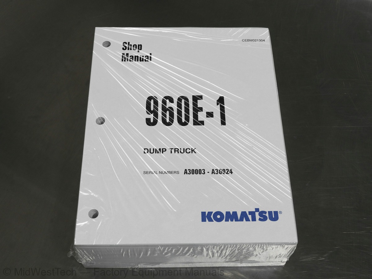
Komatsu 960E -1 Dump Truck Service Manual
1,004 pages · Publication CEBM021304
Added to your cart. View cart
- Models
- 960E -1
- Serial coverage
- A30003-A30024
- Manual type
- Service Manual
- Pages
- 1,004
- Publication
- CEBM021304
- Condition
- Brand new
What's inside
From the manual's own table of contents: 203 sections, 380 entries. See sample pages (PDF, 811 KB)
Show all 203 sections
Fuel, coolant and lubricants34 topics
- Steering circuit operation
- Steering circuit components
- Flow amplifier operation
- Steering/brake pump operation
- Steering cylinder wear data
- Hoist circuit operation
- Hoist circuit components
- Hoist pilot valve operation
- Hoist cylinder wear data
- General information
- Service brake circuit operation
- Secondary braking and auto apply
- Parking brake circuit operation
- Wheel brake lock circuit operation
- Brake warning circuit operation
- Brake assembly wear data
- Front suspension wear data
- Rear suspension wear data
- Battery supply system
- Auxiliary control cabinet components
- Relay boards
- Body-up switch
- Hoist limit switch
- Sensors
- Interface module inputs and outputs
- General system operation
- AC drive system components
- PSC software functions
- Alernator field control
- Event detection and processing
- Event logging and storage
- Serial data communications
- Abnormal conditions/overriding functions
- AC drive system component table
KOMTRAX Plus controller checkout procedure38 topics
- Payload meter initial setting procedure
- Interface module software
- Interface module checkout procedures
- Service tools and equipment
- Detecting leaks
- System performance test
- Checking system oil
- System flushing
- Installing the manifold gauge set
- Recovering and recycling refrigerant
- Evacuating the air conditioning system
- Charging the air conditioning system
- Fuse and circuit breaker locations
- DID panel fault code tables
- Fault Code A001: Left front suspension pressure sensor signal high
- Fault Code A002: Left front suspension pressure sensor signal low
- Fault Code A003: Right front suspension pressure sensor signal high
- Fault Code A004: Right front suspension pressure sensor signal low
- Fault Code A005: Left rear suspension pressure sensor signal high
- Fault Code A006: Left rear suspension pressure sensor signal low
- Fault Code A007: Right rear suspension pressure sensor signal high
- Fault Code A008: Right rear suspension pressure sensor signal low
- Fault Code A009: Incline sensor signal high
- Fault Code A010: Incline sensor signal low
- Fault Code A011: Payload meter speed sensor signal has failed
- Fault Code A013: Body up switch has failed
- Fault Code A014: Payload meter checksum computation has failed
- Fault Code A016: Payload meter write to flash memory has failed
- Fault Code A017: Payload meter flash memory read has failed
- Fault Code A018: Right rear flat suspension cylinder warning
- Fault Code A019: Left rear flat suspension cylinder warning
- Fault Code A022: Carryback load excessive
- Fault Code A100: An open circuit breaker has been detected on a relay board
- Fault Code A101: High pressure detected across an hydraulic pump filter
- Fault Code A105: Fuel level sensor shorted to ground, indicating a false high fuel level
- Fault Code A107: GE has generated a propel system caution
- Fault Code A108: GE has generated a propel system temperature caution
- Fault Code A109: GE has generated a propel system reduced level signal
Fault Code A207: Ambient temperature sensor is low36 topics
- Fault Code A212: Bad truck speed signal
- Fault Code A213: Parking brake should have applied but is detected as not having applied
- not having released
- Fault Code A215: Brake auto apply valve circuit is defective
- command valve circuit
- has been attempted
- Fault Code A230: Parking brake has been requested while truck still moving
- Fault Code A231: The body is up with engine running and brakes not on
- Fault Code A235: Steering accumulator is in the process of being bled down
- Fault Code A236: The steering accumulator has not properly bled down after 90 seconds
- Fault Code A237: The CAN/RPC connection to the display is open
- Fault Code A240: The key switch input to the interface module is open
- Fault Code A242: Fuel gauge within the dash display panel is defective
- is defective
- Fault Code A246: Payload meter reports truck overload
- Fault Code A247: Low steering pressure warning
- Fault Code A248: Status module within the dash display panel is defective
- Fault Code A249: Red warning lamp within the dash display (driven by IM) is shorted
- Fault Code A250: Battery voltage is low with the truck parked
- shorted to ground
- Fault Code A252: Start enable output circuit is either open or shorted to ground
- Fault Code A253: Steering bleed circuit is not open while running
- Fault Code A256: Red warning lamp in the dash display (driven by IM) is open
- Fault Code A257: Payload CAN/RPC is not connected
- Fault Code A258: Steering accumulator bleed pressure switch circuit is defective
- Fault Code A260: Parking brake failure
- Fault Code A261: Low brake accumulator pressure warning
- Fault Code A262: Steering bleed valve circuit open during shutdown
- Fault Code A264: Parking brake relay circuit is defective
- Fault Code A265: Service brake failure
- Fault Code A266: Selector lever was not in park while attempting to crank engine
- Fault Code A267: Parking brake was not set while attempting to crank engine
- Fault Code A268: Secondary engine shutdown while cranking
- Fault Code A270: Brake lock switch power supply is not on when required
- Fault Code A271: Shifter not in gear
- Fault Code A272: Brake lock switch power supply is not off when required
Fault Code A329: Data link reports the body is not down but wired input says it is36 topics
- wired input does not
- Fault Code A350: Overload on output 1B
- Fault Code A351: Overload on output 1E
- Fault Code A352: Overload on output 1H
- Fault Code A353: Overload on output 1J
- Fault Code A354: Overload on output 1K
- Fault Code A355: Overload on output 1L
- Fault Code A356: Overload on output 1M
- Fault Code A357: Overload on output 1N
- Fault Code A358: Overload on output 1P
- Fault Code A359: Overload on output 1R
- Fault Code A360: Overload on output 1S
- Fault Code A361: Overload on output 1T
- Fault Code A362: Overload on output 1U
- Fault Code A363: Overload on output 1X
- Fault Code A364: Overload on output 1Y
- Fault Code A365: Overload on output 1Z
- Preliminary checks
- Diagnosis of gauge readings and system performance
- Troubleshooting by manifold gauge set readings
- Pumping unit LED signals
- General information for tires and rims
- Removal and installation of front wheel
- Removal and installation of rear wheel
- Removal and installation of tires
- Removal and installation of front wheel hub and spindle
- Disassembly and assembly of front wheel hub and spindle
- Removal and installation of rear axle
- Removal and installation of anti-sway bar
- Removal and installation of pivot pin
- Pivot eye and bearing service
- Removal and installation of wheel motor
- Removal and installation of rear brake assembly
- Removal and installation of brake valve
- Disassembly and assembly of brake valve
- Removal and installation of dual relay valve
Removal and installation of windshield wiper motor33 topics
- Removal and installation of windshield wiper arm
- Removal and installation of windshield wiper linkage
- Removal and installation of operator seat
- Removal and installation of passenger seat
- Removal and installation of seat belts (standard seats)
- Removal and installation of seat belts (optional seats)
- Removal and installation of dump body
- Removal and installation of body pads
- Removal and installation of diagonal ladder/hood and grille assembly
- Removal and installation of right deck
- Removal and installation of left deck
- Removal and installation of fuel tank
- Removal and installation of fuel gauge sender
- Disassembly and assembly of fuel tank breather
- Removal and installation of hydraulic tank
- Replacement of air conditioning system components
- Diasassembly and assembly of compressor clutch
- Removal and installation of power module
- Removal and installation of alternator
- Removal and installation of engine
- Removal and installation of radiator
- Repairing the radiator
- Steering, hoist and brake cooling hydraulic circuit diagram
- Brake hydraulic circuit diagram
- Electrical circuit diagram - index & symbols
- Electrical circuit diagram - circuit locator sheet
- Electrical circuit diagram - battery box
- Electrical circuit diagram - 24V power distribution & circuit protection
- Electrical circuit diagram - engine control wiring
- Electrical circuit diagram - keyswitch, timed engine shutdown & auto lube system
- Electrical circuit diagram - engine start circuit
- Electrical circuit diagram - brake control wiring
- Electrical circuit diagram - steering & hoist pressure switch wiring
Inside this manual
Real pages from this service manual (1,004 pages). Open the sample pages (PDF, 810 KB)

- Specifications, page 43: 00 Index and foreword
- Troubleshooting, page 658: Fault Code A350: Overload on output 1B
- Diagram, page 973: XS5706-0 JUN 08
- Color page, page 46: 00 Index and foreword
- Color page, page 899: 50 Disassembly and assembly
- Foldout diagram, page 970: XS5703-1 APR 09
Other manuals for this machine
Save 10% on 2 manuals, 15% on 3 or more. Other manuals for the 960E -1 are listed below. Editions cover different serial number ranges: check the serial coverage and tick only the ones that match your machine.
Added to your cart. View cart
This is a service manual
Here's how it compares to the other manual types.
Service manual
Factory repair procedures and technical information such as specifications, troubleshooting, and wiring and hydraulic diagrams, for the models and systems the manual covers. See What's inside for its topics.
Operator's manual
Safe operation, controls, maintenance schedules, lubrication points, inspections, and basic checks. Repair procedures are in the service manual.
Parts manual
Illustrated diagrams with factory part numbers for identifying components and ordering parts. Repair procedures are in the service manual.
Engine service manuals are sometimes sold separately, since certain machine models were offered with more than one engine option.
What it's used for
Factory manual for in-house farm and construction shop use. Straightforward, complete, and easy to follow. It contains the OEM information dealership service departments and parts counters use to diagnose problems, identify components, and perform maintenance or repairs correctly.
Service shops and owner/operators who repair their own equipment
Identifying correct parts and seeing how assemblies come apart and go back together
Keeping equipment running with less downtime
Factory manual, 1,004 pages
Quantity one is the manual described above.
Fast free USA shipping
Ships in 1 business day.
60-day returns
Free if the mistake is ours. A manual ordered in error must come back unopened in its shrink-wrap; you pay return shipping and a 20% restocking fee applies. Return policy
Binder not included
Manuals over about 300 pages may need a standard 3-ring binder, which you can buy locally to keep the pages organized for shop use.
Other editions and similar models
Questions about model, serial number, engine coverage or contents? Contact us before purchasing and we'll help confirm it's the right manual. Please verify the manual type, machine model, serial number range and engine coverage before purchasing: manuals ordered in error carry a 20% restocking fee (return policy).