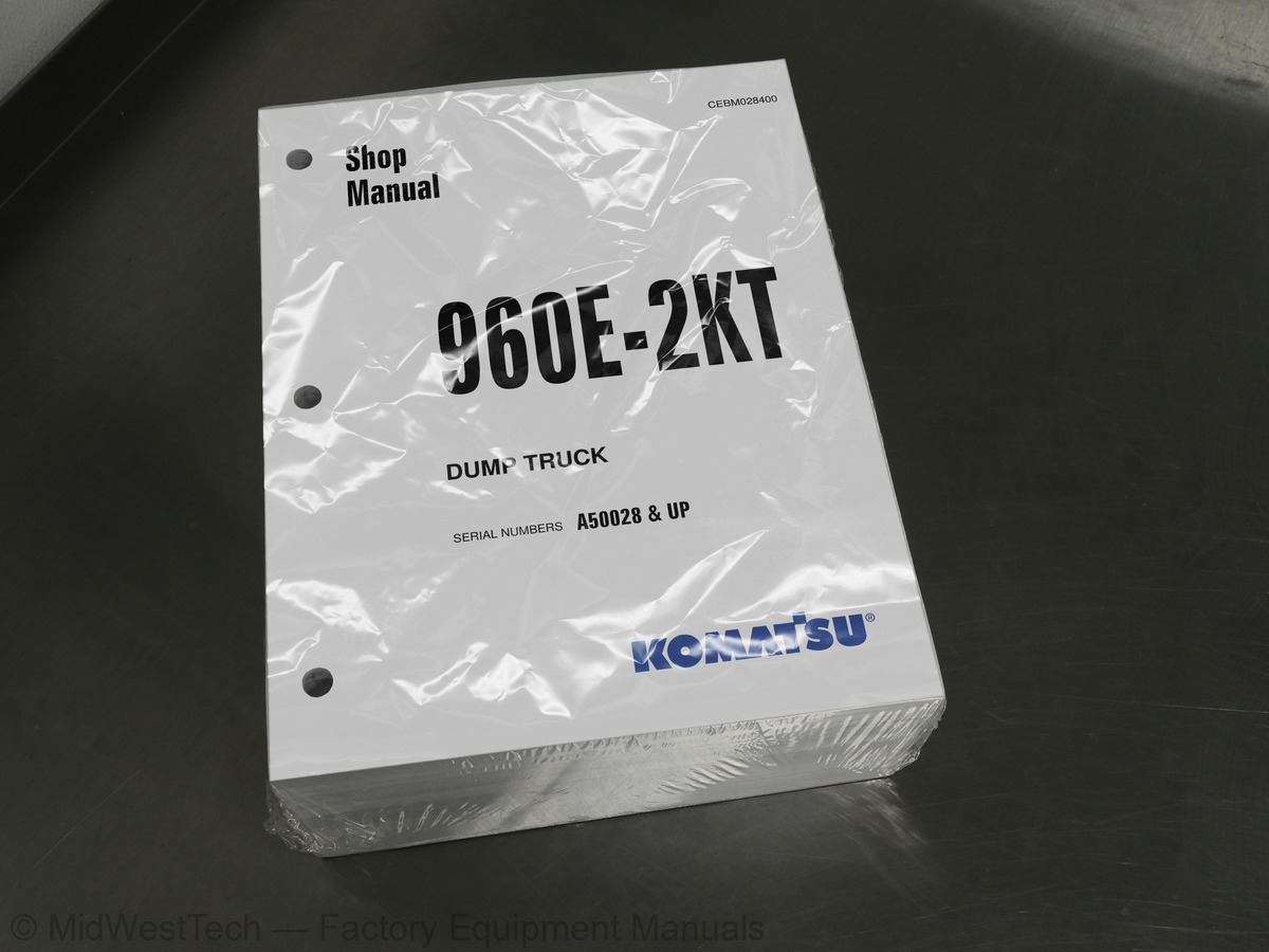
Komatsu 960E-2KT Dump Truck Service Manual
1,775 pages · Publication CEBM028400
Added to your cart. View cart
- Models
- 960E-2KT
- Serial coverage
- A50028 & up
- Manual type
- Service Manual
- Pages
- 1,775
- Publication
- CEBM028400
- Condition
- Brand new
What's inside
From the manual's own table of contents: 365 sections, 700 entries. See sample pages (PDF, 759 KB)
Show all 365 sections
Weight table36 topics
- Fuel, coolant and lubricants
- Steering circuit operation
- Steering circuit components
- Flow amplifier operation
- Steering/brake pump operation
- Steering cylinder wear data
- Hoist circuit operation
- Hoist circuit components
- Hoist pilot valve operation
- Hoist cylinder wear data
- General information
- Service brake circuit operation
- Secondary braking and auto apply
- Parking brake circuit operation
- Wheel brake lock circuit operation
- Brake warning circuit operation
- Brake assembly wear data
- Front suspension wear data
- Rear suspension wear data
- Battery supply system
- Auxiliary control cabinet components
- Relay boards
- Body position switches (With proximity switch and magnet)
- Sensors
- Interface module inputs and outputs
- SR rectifier module
- ST module (auxiliary voltage inverter)
- SD phase modules
- SR/ST/SD module removal
- Inverter cabinet layout
- Inverter cabinet water flow
- Field regulator
- Field regulator (discharge resistor)
- Gate unit power supply
- Gate unit power supply (diode)
- Gate unit power supply (tuning resistor)
Grid box blower motor grease fittings40 topics
- Main alternator
- Main alternator circuit diagram
- IGBT – inverter/chopper phase module
- Troubleshooting information
- Main input rectifier module
- Internal circuit diagram
- Upper ground tie resistor
- Lower ground tie resistor
- Troubleshooting
- Speed sensor, alternator
- Speed sensors, wheel motors
- Traction motor
- Grid box
- Principles of refrigeration
- Air conditioning system components
- Air conditioning system electrical circuit
- Operation
- Remote tank fill system
- SIBAS® 32 Traction Control Unit (TCU)
- Overview of the SIBAS® 32 systems
- Removing and installing the SIBAS® 32 cards
- SIBAS® 32 card device names
- Structure of SIBAS® 32 card part number
- SIBAS® 32 card interchangeability
- SIBAS® 32 card interactions
- SIBAS® 32 card detailed information
- Blower subassembly
- CPU card
- DSP card
- I/O card
- TRACO card (optional)
- Input voltage/frequency card
- I/O analog card
- Output pulse amplifier card
- Input temperature sensor card
- UWS card
- Digital input card
- Power start-up unit card
- Binary output contactor drive card
- 24V / 24V power supply
Recovering and recycling refrigerant43 topics
- Evacuating the air conditioning system
- Charging the air conditioning system
- Interface module software
- Interface module checkout procedures
- Abbreviations
- Precautions
- Qualified person
- Customer monitor for SIBAS® 32 control units
- Installing and calling the customer monitor
- Environment variables
- Communication with the SIBAS® 32 control unit
- Calling up the customer monitor
- Monitor prompt
- Notes on operation of the customer monitor
- Command buffer
- Structure of the monitor windows
- Window menu
- Set Menu
- Applic. Menu
- Hardw. Menu
- Hardware-Oriented Access via the Customer Monitor
- Graphic Menu
- Traco Menu
- HW-Traco
- SW-Traco
- DAC_Traco
- Events Menu
- STatistics
- History
- LEL:Last EvL
- LES:Last EvS
- DLL:DC,LastL
- DLS:DC,LastS
- DAL:DC,All L
- DAS:DC,All S
- ML:Memory L
- MS:Memory S
- CN:Clear Norm
- CA:Clear All
- Test-Code
- DS:Diag-Strc
- User Menu
- DAC_IO
Fault Code A004: Right front suspension pressure sensor signal low42 topics
- Fault Code A005: Left rear suspension pressure sensor signal high
- Fault Code A006: Left rear suspension pressure sensor signal low
- Fault Code A007: Right rear suspension pressure sensor signal high
- Fault Code A008: Right rear suspension pressure sensor signal low
- Fault Code A009: Incline sensor signal high
- Fault Code A010: Incline sensor signal low
- Fault Code A011: Payload meter speed sensor signal has failed
- Fault Code A013: Body up switch has failed
- Fault Code A014: Payload meter checksum computation has failed
- Fault Code A016: Payload meter write to flash memory has failed
- Fault Code A017: Payload meter flash memory read has failed
- Fault Code A018: Right rear flat suspension cylinder warning
- Fault Code A019: Left rear flat suspension cylinder warning
- Fault Code A022: Carryback load excessive
- Fault Code A100: An open circuit breaker has been detected on a relay board
- Fault Code A101: High pressure detected across an hydraulic pump filter
- Fault Code A105: Fuel level sensor shorted to ground, indicating a false high fuel level
- Fault Code A111: Low steering pressure warning for storage by KOMTRAX Plus
- Fault Code A115: Low steering precharge pressure detected
- Fault Code A118: Brake pressure is low while in brake lock
- Fault Code A126: Oil level in the hydraulic tank is low
- Fault Code A127: IM-furnished +5 volt output for sensors is low
- Fault Code A128: IM-furnished +5 volt output for sensors is high
- Fault Code A139: Low fuel warning for storage by KOMTRAX Plus and for use by A310
- advance level 1 for cooling of hydraulic oil
- advance level 2 for cooling of hydraulic oil
- Fault Code A152: Starter failure
- Fault Code A153: Battery voltage is low with the truck in operation
- Fault Code A154: Battery charging voltage is excessive
- Fault Code A155: Battery charging voltage is low
- Fault Code A166: Left rear hydraulic oil temperature sensor is low
- Fault Code A167: Right rear hydraulic oil temperature sensor is low
- Fault Code A168: Left front hydraulic oil temperature sensor is low
- Fault Code A169: Right front hydraulic oil temperature sensor is low
- Fault Code A170: Left rear hydraulic oil temperature sensor is high
- Fault Code A171: Right rear hydraulic oil temperature sensor is high
- Fault Code A172: Left front hydraulic oil temperature sensor is high
- Fault Code A173: Right front hydraulic oil temperature sensor is high
- Fault Code A184: J1939 data link is not connected
- Fault Code A190: Auto lube control has detected an incomplete lube cycle
- Fault Code A194: Left front hydraulic oil temperature is high
- Fault Code A195: Right front hydraulic oil temperature is high
Fault Code A258: Steering accumulator bleed pressure switch circuit is defective39 topics
- Fault Code A260: Parking brake failure
- Fault Code A261: Low brake accumulator pressure warning for display to operator
- Fault Code A262: Steering bleed valve circuit open during shutdown
- Fault Code A264: Parking brake relay circuit is defective
- Fault Code A265: Service brake failure
- Fault Code A266: Selector switch was not in park while attempting to crank engine
- Fault Code A267: Parking brake was not set while attempting to crank engine
- Fault Code A268: Secondary engine shutdown while cranking
- Fault Code A270: Brake lock switch power supply is not on when required
- Fault Code A271: Shifter not in gear
- Fault Code A272: Brake lock switch power supply is not off when required
- pressure switch circuit
- Fault Code A275: A starter has been detected as engaged without a cranking attempt
- Fault Code A277: Parking brake applied while loading
- Fault Code A278: Service brake applied while loading
- Fault Code A279: Low steering pressure switch is defective
- Fault Code A280: Steering accumulator bleeddown switch is defective
- Fault Code A281: Brake lock degrade switch is defective
- the engine running has been reached
- was not set
- operated
- Fault Code A285: The parking brake was not set when the keyswitch was turned off
- Fault Code A286: A fault was detected in the shutdown delay relay circuit
- keyswitch circuit is off
- Fault Code A303: Shifter is defective
- Fault Code A304: Auto lube grease level fault
- Fault Code A305: Auto lube circuit is defective
- Fault Code A309: No brakes applied when expected
- Fault Code A310: Low fuel warning
- Fault Code A311: Brake lock switch is on when it should not be
- Fault Code A312: DCDC converter 12 volt circuit sensing is producing low readings
- Fault Code A313: DCDC converter 12 volt circuit sensing is producing high readings
- Fault Code A315: DCDC converter 12 volt circuit is low
- Fault Code A316: Starter engagement has been attempted with engine running
- Fault Code A317: Operation of brake auto apply valve without a detected response
- Fault Code A318: Unexpected power loss to Interface Module
- Fault Code A328: Drive system not powered up
- Fault Code A350: Overload on output 1B
- Fault Code A351: Overload on output 1E
L1B DSP A: SW-Traco triggered45 topics
- L1B DSP A: SW-Traco full
- L3C DSP A: Time slice overflow T1
- L3C DSP A: Time slice overflow T2
- L3C DSP A: Time slice overflow T3
- L3C DSP A: Time slice overflow T4
- L1A DSP A: Communication HSCX data from DSP B missing
- L1A DSP A: Communication HSCX data from DSP T missing
- L3C DSP A: Current offset during pulse block
- L3C DSP A: Current offset during no pulse block
- L3A DSP A: Overcurrent fault
- L3C DSP A: Current transducer defective phase U
- L3C DSP A: Current transducer defective phase W
- L1A DSP A: Modulation software fault
- L3A DSP A: Active current controller at limit
- L3A DSP A: Active current reference at limit
- L1A DSP A: Braking chopper controller at limit
- L3C DSP A: Phase unbalance too large
- L3A DSP A: Pulse block by DSP software
- L3C DSP A: U/F Card defective
- L3C DSP A: Difference in current of phase U over limit
- L3C DSP A: Difference in current of phase W over limit
- L3C DSP B: Initialization fault detected by DSP
- L3C DSP B: SW-Watchdog
- L3C DSP B: Initialization fault detected by CPU
- L1B DSP B: SW-Traco triggered
- L1B DSP B: SW-Traco full
- L3C DSP B: Time slice overflow T1
- L3C DSP B: Time slice overflow T2
- L3C DSP B: Time slice overflow T3
- L3C DSP B: Time slice overflow T4
- L1A DSP B: Communication HSCX data from DSP A missing
- L1A DSP B: Communication HSCX data from DSP T missing
- L3C DSP B: Current offset during pulse block
- L3C DSP B: Current offset during no pulse block
- L3A DSP B: Overcurrent fault
- L3C DSP B: Current transducer defective phase V
- L3C DSP B: Current transducer defective phase W
- L1A DSP B: Modulation software fault
- L3A DSP B: Active current controller at limit
- L3A DSP B: Active current reference at limit
- L1A DSP B: Braking chopper controller at limit
- L3C DSP B: Phase unbalance too large
- L3A DSP B: Pulse block by DSP software
- L3C DSP B: U/F Card defective
- L3C DSP B: Difference in current of phase V over limit
L3A IO: DC link voltage B level 1 exceeded45 topics
- L3C IO: Trolley line overvoltage
- L3B IO: Trolley line overcurrent
- L2B IO: Trolley line current transducer faulty
- L2B IO: Trolley line voltage transducer faulty
- L3A IO: Throttle pedal out of range
- L3A IO: Retard pedal out of range
- L1A IO: Cruise speed control module out of range
- L3C UWSA1: Supervision bus clock
- L3C UWSA1: Supervision module clock
- L3C UWSA1: Incorrect FPGA version identifier
- L3C UWSA1: Incorrect FPGA project identifier
- L3C UWSA1: GW Comparator faulty during start-up test
- L1A UWSA1: ADC Faulty
- L3C UWSA1: Configuration failure
- L1A UWSA1: Hardware failure counter / processor
- L3A UWSA1: Peak current protection active
- L3D UWSA1: Peak current protection pulse start
- L3D UWSA1: Number of peak current protection >limit
- L3D UWSA1: Supervision switching frequency
- L1A UWSA1: Overvoltage level 1 exceeded
- L3D UWSA1: Limit 5 overcurrent phase U
- L3D UWSA1: Limit 5 overcurrent phase V
- L3D UWSA1: Limit 5 overcurrent phase W
- L3D UWSA1: Limit 5 overvoltage DC bus
- L3D UWSA1: Checkback INVA1 L1U faulty
- L3D UWSA1: Checkback INVA1 L1L faulty
- L3D UWSA1: Checkback INVA1 L2U faulty
- L3D UWSA1: Checkback INVA1 L2L faulty
- L3D UWSA1: Checkback INVA1 L3U faulty
- L3D UWSA1: Checkback INVA1 L3L faulty
- L3D UWSA1: Checkback chopper A faulty
- L3C UWSB1: Supervision bus clock
- L3C UWSB1: Supervision module clock
- L3C UWSB1: Incorrect FPGA version identifier
- L3C UWSB1: Incorrect FPGA project identifier
- L3C UWSB1: GW Comparator faulty during start-up test
- L1A UWSB1: ADC Faulty
- L3C UWSB1: Configuration failure
- L1A UWSB1: Hardware failure counter / processor
- L3A UWSB1: Peak current protection active
- L3D UWSB1: Peak current protection pulse start
- L3D UWSB1: Number of peak current protection >limit
- L3D UWSB1: Supervision switching frequency
- L1A UWSB1: Overvoltage level 1 exceeded
- L3D UWSB1: Limit 5 overcurrent phase V
L3D UWSB2: Supervision switching frequency45 topics
- L1A UWSB2: Overvoltage level 1 exceeded
- L3D UWSB2: Limit 5 overcurrent phase V1
- L3D UWSB2: Limit 5 overcurrent phase U1
- L3D UWSB2: Limit 5 overcurrent phase W1
- L3D UWSB2: Limit 5 overvoltage DC bus
- L3D UWSB2: Checkback INVB2 L1U Faulty
- L3D UWSB2: Checkback INVB2 L1L Faulty
- L3D UWSB2: Checkback INVB2 L2U Faulty
- L3D UWSB2: Checkback INVB2 L2L Faulty
- L3D UWSB2: Checkback INVB2 L3U Faulty
- L3D UWSB2: Checkback INVB2 L3L Faulty
- L3D UWSB2: Checkback chopper D Faulty
- L3C UWSST: Supervision bus clock
- L3C UWSST: Supervision module clock
- L3C UWSST: Incorrect FPGA version identifier
- L3C UWSST: Incorrect FPGA project identifieR
- L3C UWSST: GW Comparator faulty during start-up test
- L1A UWSST: ADC Faulty
- L3C UWSST: Configuration failure
- L1A UWSST: Hardware failure counter / processor
- L3A UWSST: Peak current protection active
- L3D UWSST: Number of peak current protection >limit
- L3D UWSST: Supervision switching frequency
- L3C UWSST: Crowbar is fired without command
- L3D UWSST: Limit 5 overcurrent phase U
- L3D UWSST: Limit 5 overcurrent phase V
- L3D UWSST: Limit 5 overcurrent phase W
- L3D UWSST: Limit 5 overvoltage DC bus
- L3D UWSST: Checkback INVST L1U Faulty
- L3D UWSST: Checkback INVST L1L Faulty
- L3D UWSST: Checkback INVST L2U Faulty
- L3D UWSST: Checkback INVST L2L Faulty
- L3D UWSST: Checkback INVST L3U Faulty
- L3D UWSST: Checkback INVST L3L Faulty
- L3C UWSST: Checkback crowbar faulty
- L1A BUS: CAN Communication failure
- L1A BUS: Serial link communication failure
- L1A BUS: Truck is over loaded
- L1B TR: Transient traco is triggered
- L1B TR: Transient traco is full
- L1A ETM: ADC Failure for ETM1
- L1A ETM: ADC Failure for ETM2
- L1A ETM: ADC Failure for ETM3
- L1A ETM: ADC Failure for ETM4
- L1A MEFA: ADC Failure
Inside this manual
Real pages from this service manual (1,775 pages). Open the sample pages (PDF, 758 KB)

- Specifications, page 209: 10 Structure and Function
- Troubleshooting, page 803: Fault Code A317: Operation of brake auto apply valve without a detected response
- Diagram, page 1,721: ELECTRIC SCHEMATIC
- Color page, page 1,644: 50 Disassembly and assembly
- Color page, page 244: 10 Structure and Function
- Foldout diagram, page 1,761: ELECTRIC SCHEMATIC
Other manuals for this machine
Save 10% on 2 manuals, 15% on 3 or more. Other manuals for the 960E-2KT are listed below. Editions cover different serial number ranges: check the serial coverage and tick only the ones that match your machine.
Added to your cart. View cart
This is a service manual
Here's how it compares to the other manual types.
Service manual
Factory repair procedures and technical information such as specifications, troubleshooting, and wiring and hydraulic diagrams, for the models and systems the manual covers. See What's inside for its topics.
Operator's manual
Safe operation, controls, maintenance schedules, lubrication points, inspections, and basic checks. Repair procedures are in the service manual.
Parts manual
Illustrated diagrams with factory part numbers for identifying components and ordering parts. Repair procedures are in the service manual.
Engine service manuals are sometimes sold separately, since certain machine models were offered with more than one engine option.
What it's used for
Factory manual for in-house farm and construction shop use. Straightforward, complete, and easy to follow. It contains the OEM information dealership service departments and parts counters use to diagnose problems, identify components, and perform maintenance or repairs correctly.
Service shops and owner/operators who repair their own equipment
Identifying correct parts and seeing how assemblies come apart and go back together
Keeping equipment running with less downtime
Factory manual, 1,775 pages
Quantity one is the manual described above.
Fast free USA shipping
Ships in 1 business day.
60-day returns
Free if the mistake is ours. A manual ordered in error must come back unopened in its shrink-wrap; you pay return shipping and a 20% restocking fee applies. Return policy
Binder not included
Manuals over about 300 pages may need a standard 3-ring binder, which you can buy locally to keep the pages organized for shop use.
Questions about model, serial number, engine coverage or contents? Contact us before purchasing and we'll help confirm it's the right manual. Please verify the manual type, machine model, serial number range and engine coverage before purchasing: manuals ordered in error carry a 20% restocking fee (return policy).