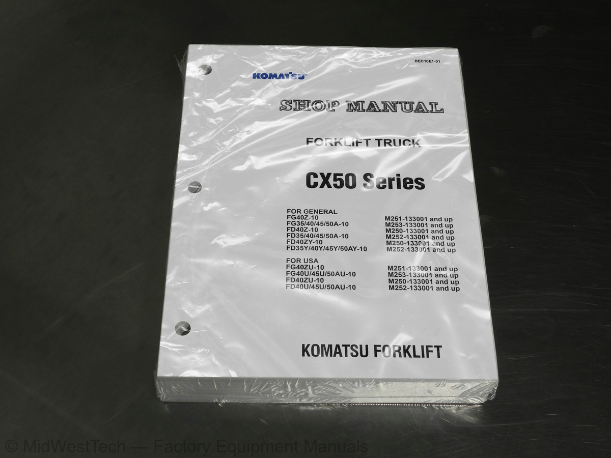
Komatsu CX50, FG40Z-10, FG35, FG40, FG45, FG50A-10, FD40Z-10, FD35, FG40, FG45, FG50A-10 and 13 more Forklift Service Manual
755 pages · Publication BEC10E1-01 · CX50, FG40Z-10, FG35, FG40, FG45, FG50A-10, FD40Z-10, FD35, FG40, FG45, FG50A-10, FD40ZY-10, FD35Y, FG40Y, FG45Y, FG50AY-10, FG40ZU-10, FG40U, FG45U, FG50AU-10, FD40ZU-10, FD40U, FG45U, FG50AU-10
Added to your cart. View cart
- Models
- CX50, FG40Z-10, FG35, FG40, FG45, FG50A-10, FD40Z-10, FD35, FG40, FG45, FG50A-10, FD40ZY-10, FD35Y, FG40Y, FG45Y, FG50AY-10, FG40ZU-10, FG40U, FG45U, FG50AU-10, FD40ZU-10, FD40U, FG45U, FG50AU-10
- Serial coverage
- M250, M251, M252, M253-133001 and up
- Manual type
- Service Manual
- Pages
- 755
- Publication
- BEC10E1-01
- Condition
- Brand new
What's inside
From the manual's own table of contents: 116 sections, 230 entries. See sample pages (PDF, 957 KB)
Show all 116 sections
Hydraulic tank piping diagram46 topics
- Control valve piping diagram (tank – control valve)
- Work equipment piping diagram (control valve – tilt cylinder/lift cylinder)
- Attachment piping diagram
- Work equipment and steering pump
- Control valve
- CLSS
- Each function and operation of each valve
- Tilt cylinder
- Lift cylinder
- Mast
- Fork carriage
- Fork
- Accelerator pedal sensor
- ISO controller (Operator Presence Sensing (OPS) system)
- EPACS controller
- Instrument panel
- Engine starting circuit
- Engine stopping circuit
- Electrical system wiring diagram
- Sensors
- Switches
- Lamps
- Horn and buzzer
- Flasher
- F/R solenoid valve and F2 solenoid valve
- Relay box
- Resistor
- Diode
- Fuse
- Battery
- Standard value table
- Check of troubleshooting software functions and failure codes
- Hydraulic piping pressure release procedure
- Replacement of engine oil and engine oil filter
- Replacement of fuel filter
- Cleaning of radiator
- Check of air cleaner and replacement of cleaner element
- Oil level check and oil replacement of differential case
- Oil replacement and strainer cleaning of TORQFLOW transmission
- Testing power train oil pressure
- Check of hydraulic tank
- Measurement of wear amount of service brake disc
- Check of parking brake
- Air bleeding procedure
- Adjustment of brake pedal
- Adjustment of inching pedal
Failure code [[!]: 2 flashings, [N]: Flashing, [L]: OFF] F/R lever trouble5 topics
- abnormality or N (neutral) lamp and lift interlock warning lamp output abnormality
- Lift interlock relay output abnormality (1)
- Lift interlock relay output abnormality (2)
- Travel interlock relay output abnormality (1)
- Travel interlock relay output abnormality (2)
Failure code [LED: 4 flashings] Tyre angle sensor abnormality18 topics
- Engine does not start
- Engine does not stop
- Lift truck cannot travel
- Parking brake reminder alarm does not sound or does not stop sounding
- Travel direction is not changed normally
- Lift truck cannot move work equipment
- Work equipment cannot be locked
- EPACS is abnormal
- Headlamp, clearance lamp, tail lamp and license plate lamp do not light or go off
- Turn signal lamps do not light or go off
- Brake lamps do not light or go off
- Backup lamps do not light or go off
- Backup buzzer does not sound or does not stop sounding
- Horn does not sound or does not stop sounding
- Fuel level is not displayed normally
- Fuel (Gasoline) level is not displayed normally
- Engine preheater does not operate normally
- Headlamp, clearance lamp and tail lamp do not light or go off
Mast is unstable during travel with load45 topics
- Lift and tilt levers do not move smoothly and they are heavy
- Engine speed lowers remarkably or engine stalls when work equipment is operated
- Large shocks are made when work equipment is started and stopped
- Another part of work equipment moves when work equipment is relieved singly
- Work equipment speed or force is low
- or engine stalls
- Work equipment and steering system do not move
- Abnormal sound is heard from around work equipment and steering pump
- Work equipment fine control performance is low or response is low
- or only work equipment does not move
- Work equipment (lift-up) does not move, moves but slow or moves but force is low
- Lift cylinder drift is large (while operator is not in operator seat)
- Lift cylinder drift is large (while operator is in operator seat)
- low or response is low
- Fork does not lower
- Mast does not tilt/tilts but slow/tilts but force is low
- Tilt cylinder natural forward drift is large
- Attachment does not move/moves but low/moves but force is low
- Attachment cylinder natural drift is large
- Steering is heavy
- Large shock is made when steering wheel is returned
- operated simultaneously
- Steering is heavy when work equipment and steering are operated simultaneously
- Method of using this manual
- Special tool list
- How to use LOCTITE
- Removal and installation of power train
- Removal and installation of front axle
- Centering of power train
- Disassembly and assembly of transmission
- Disassembly and assembly of torque converter
- Disassembly and assembly of drive shaft
- Disassembly and assembly of differential
- Disassembly and assembly of axle housing assembly
- Disassembly and assembly of parking brake
- Disassembly and assembly of rear axle
- Disassembly and assembly of power steering cylinder
- Disassembly and assembly of brake pedal
- Disassembly and assembly of brake valve
- Disassembly and assembly of steering valve
- Disassembly and assembly of control valve assembly
- Removal and installation of lift cylinder
- Disassembly and assembly of lift cylinder
- Disassembly and assembly of tilt cylinder
- Removal and installation of mast
Inside this manual
Real pages from this service manual (755 pages). Open the sample pages (PDF, 956 KB)
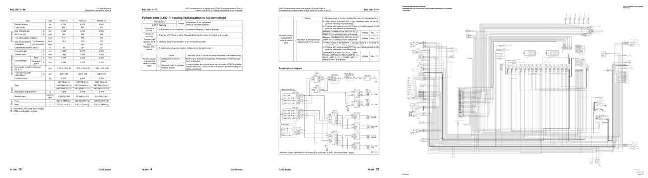
- Specifications, page 66: BEC10E1-01BA
- Troubleshooting, page 418: BEC10E1-01FD
- Diagram, page 539: BEC10E1-01FH
- Foldout diagram, page 751: Electrical diagrams and drawings
This is a service manual
Here's how it compares to the other manual types.
Service manual
Factory repair procedures and technical information such as specifications, troubleshooting, and wiring and hydraulic diagrams, for the models and systems the manual covers. See What's inside for its topics.
Operator's manual
Safe operation, controls, maintenance schedules, lubrication points, inspections, and basic checks. Repair procedures are in the service manual.
Parts manual
Illustrated diagrams with factory part numbers for identifying components and ordering parts. Repair procedures are in the service manual.
Engine service manuals are sometimes sold separately, since certain machine models were offered with more than one engine option.
What it's used for
Factory manual for in-house farm and construction shop use. Straightforward, complete, and easy to follow. It contains the OEM information dealership service departments and parts counters use to diagnose problems, identify components, and perform maintenance or repairs correctly.
Service shops and owner/operators who repair their own equipment
Identifying correct parts and seeing how assemblies come apart and go back together
Keeping equipment running with less downtime
Factory manual, 755 pages
Quantity one is the manual described above.
Fast free USA shipping
Ships in 1 business day.
60-day returns
Free if the mistake is ours. A manual ordered in error must come back unopened in its shrink-wrap; you pay return shipping and a 20% restocking fee applies. Return policy
Binder not included
Manuals over about 300 pages may need a standard 3-ring binder, which you can buy locally to keep the pages organized for shop use.
Questions about model, serial number, engine coverage or contents? Contact us before purchasing and we'll help confirm it's the right manual. Please verify the manual type, machine model, serial number range and engine coverage before purchasing: manuals ordered in error carry a 20% restocking fee (return policy).