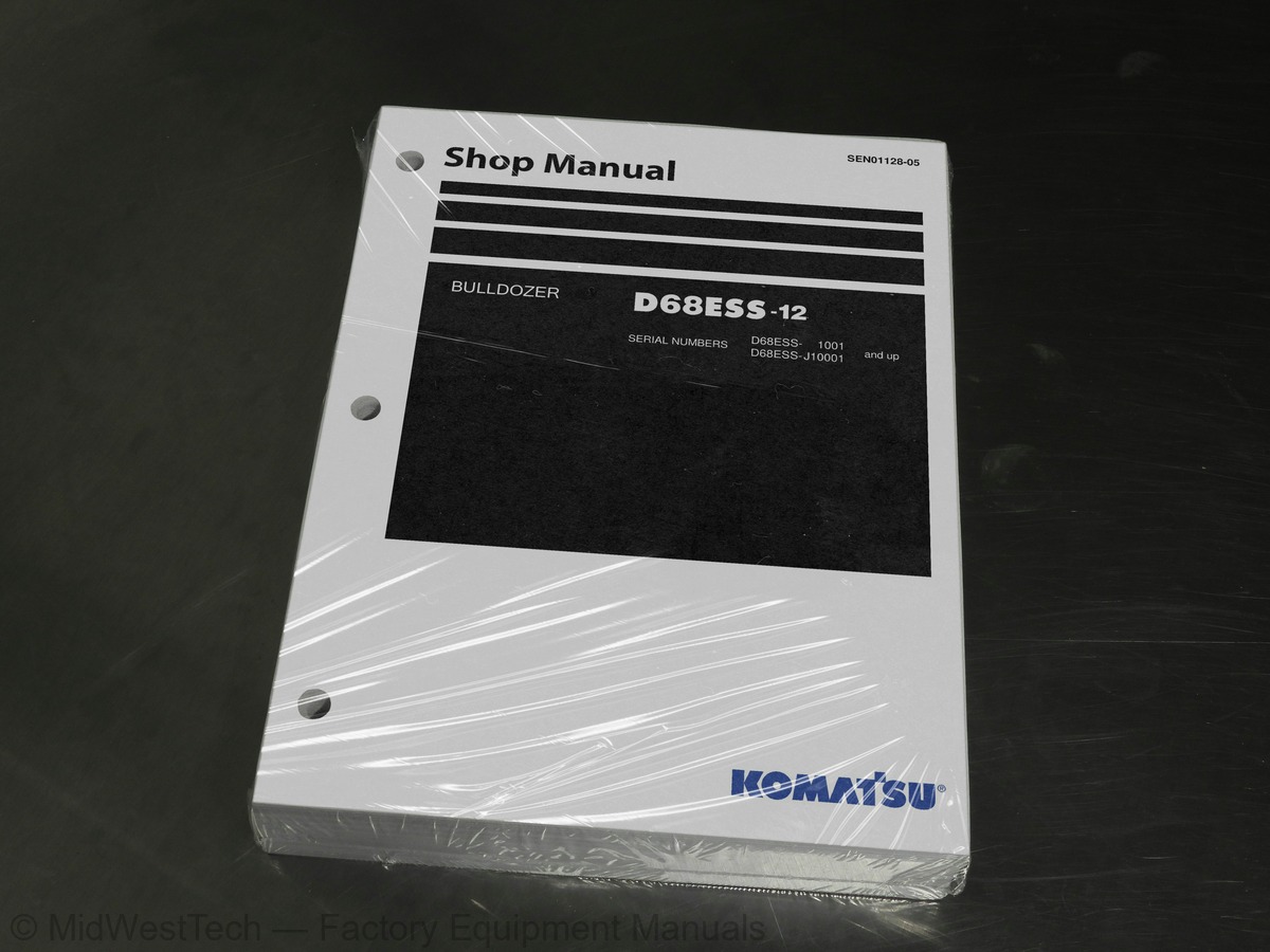
Komatsu D68ESS-12 Bulldozer Service Manual
591 pages · Publication SEN01128-05
Added to your cart. View cart
- Models
- D68ESS-12
- Serial coverage
- 1001 and up, J10001 and up
- Manual type
- Service Manual
- Pages
- 591
- Publication
- SEN01128-05
- Condition
- Brand new
What's inside
From the manual's own table of contents: 121 sections, 202 entries. See sample pages (PDF, 682 KB)
Show all 121 sections
Final drive34 topics
- Undercarriage and frame
- Main frame
- Suspension
- Track frame
- Recoil spring
- Idler
- Track roller
- Carrier roller
- Track shoe
- Hydraulic system, Part 1
- Work equipment hydraulic piping diagram
- PPC control piping diagram
- Work equipment control
- Hydraulic tank and filter
- Hydraulic pump
- Power train lubrication pump
- PPC valve (for steering)
- PPC charge valve
- Hydraulic system, Part 2
- Main control valve
- CLSS
- Functions, operation of valve
- Suction valve
- Work equipment
- Cutting edge, end bit
- Work equipment cylinder
- Electrical system
- Engine control
- Machine monitor system
- Sensors
- Standard service value table
- Standard value table for engine
- Standard value table for chassis
- Standard value table for electrical system
Hydraulic drift of blade angle is excessive47 topics
- Troubleshooting of machine monitor system (M-mode)
- Table of failure modes and causes (machine monitor system)
- Electrical circuit diagrams for each system
- Caution item lights up
- Gauge is abnormal
- Service meter does not move after engine is started
- Monitor panel lighting does not light up (front lamps are normal)
- General information on disassembly and assembly
- How to read this manual
- Coating materials list
- Special tool list
- Sketches of special tools
- Removal and installation of engine assembly
- Removal and installation of radiator and guard assembly
- Removal and installation of radiator assembly
- Removal and installation of hydraulic oil cooler assembly
- Removal and installation of fuel tank assembly
- Removal and installation of damper assembly
- Power train
- Removal and installation of PTO, torque converter and transmission assembly
- Disconnection and connection of PTO, torque converter and transmission assembly
- Disassembly and assembly of PTO assembly
- Disassembly and assembly of torque converter assembly
- Disassembly and assembly of TORQFLOW transmission assembly
- Removal and installation of torque converter main relief valve assembly
- Disassembly and assembly of torque converter main relief valve assembly
- Removal and installation of transmission control valve assembly
- Disassembly and assembly of transmission control valve assembly
- Removal and installation of steering clutch and brake assembly
- Disassembly and assembly of steering clutch and brake assembly
- Removal and installation of bevel gear and bevel gear shaft (Clutch and brake model)
- Removal and installation of brake valve assembly
- Disassembly and assembly of brake valve assembly
- Removal and installation of scavenging pump assembly
- Removal and installation of power train and lubricating oil pump assembly
- Removal and installation of final drive assembly
- Disassembly and assembly of final drive assembly
- Removal and installation of track frame assembly
- Removal and installation of recoil spring assembly
- Disassembly and assembly of recoil spring assembly
- Removal and installation of idler assembly
- Disassembly and assembly of idler assembly
- Removal and installation of track roller assembly
- Disassembly and assembly of track roller assembly
- Removal and installation of carrier roller assembly
- Disassembly and assembly of carrier roller assembly
- Removal and installation of track shoe assembly
Inside this manual
Real pages from this service manual (591 pages). Open the sample pages (PDF, 682 KB)
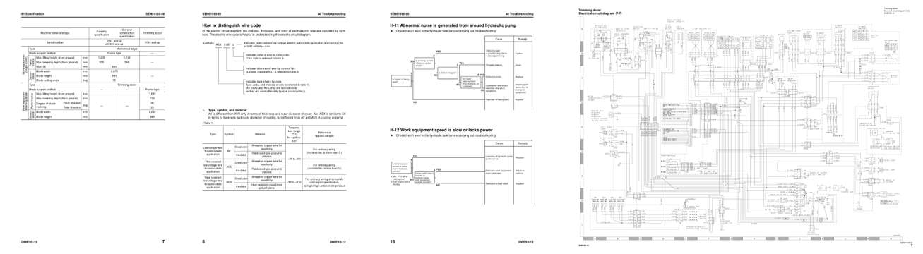
- Specifications, page 62: 01 Specification
- Diagram, page 269: 40 Troubleshooting
- Troubleshooting, page 350: 40 Troubleshooting
- Foldout diagram, page 589: Trimming dozer
This is a service manual
Here's how it compares to the other manual types.
Service manual
Factory repair procedures and technical information such as specifications, troubleshooting, and wiring and hydraulic diagrams, for the models and systems the manual covers. See What's inside for its topics.
Operator's manual
Safe operation, controls, maintenance schedules, lubrication points, inspections, and basic checks. Repair procedures are in the service manual.
Parts manual
Illustrated diagrams with factory part numbers for identifying components and ordering parts. Repair procedures are in the service manual.
Engine service manuals are sometimes sold separately, since certain machine models were offered with more than one engine option.
What it's used for
Factory manual for in-house farm and construction shop use. Straightforward, complete, and easy to follow. It contains the OEM information dealership service departments and parts counters use to diagnose problems, identify components, and perform maintenance or repairs correctly.
Service shops and owner/operators who repair their own equipment
Identifying correct parts and seeing how assemblies come apart and go back together
Keeping equipment running with less downtime
Factory manual, 591 pages
Quantity one is the manual described above.
Fast free USA shipping
Ships in 1 business day.
60-day returns
Free if the mistake is ours. A manual ordered in error must come back unopened in its shrink-wrap; you pay return shipping and a 20% restocking fee applies. Return policy
Binder not included
Manuals over about 300 pages may need a standard 3-ring binder, which you can buy locally to keep the pages organized for shop use.
Other editions and similar models
Questions about model, serial number, engine coverage or contents? Contact us before purchasing and we'll help confirm it's the right manual. Please verify the manual type, machine model, serial number range and engine coverage before purchasing: manuals ordered in error carry a 20% restocking fee (return policy).