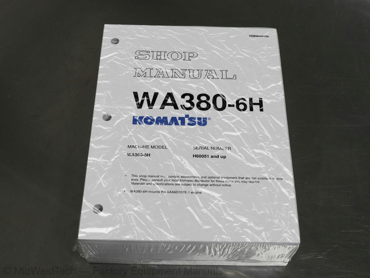
Komatsu WA380-6H Wheel Loader Service Manual
1,297 pages · Publication VEBM440100
Added to your cart. View cart
- Models
- WA380-6H
- Serial coverage
- H60051 and up
- Manual type
- Service Manual
- Pages
- 1,297
- Publication
- VEBM440100
- Condition
- Brand new
What's inside
From the manual's own table of contents: 219 sections, 472 entries. See sample pages (PDF, 1244 KB)
Show all 219 sections
Final drive48 topics
- Steering system
- Steering piping diagram
- Steering column
- Steering pump
- Steering valve
- Orbit-roll valve
- Stop valve
- Steering relief valve
- Steering cylinder
- Emergency steering motor
- Emergency steering pump
- Brake system
- Brake piping diagram
- Charge valve
- Brake valve
- Accumulator (for brake)
- Brake
- Parking brake control
- Parking brake
- Parking brake solenoid valve
- Emergency parking brake release valve
- Undercarriage and frame
- Axle mount and center hinge pin
- Tires
- Hydraulic system, Part 1
- Hydraulic piping diagram
- Work equipment control lever linkage
- Hydraulic tank
- Breather
- Power train pump
- Work equipment pump
- Work equipment control valve
- CLSS
- Outline of CLSS
- Basic principle
- Each function and operation of each valve
- Hydraulic circuit diagram and names of valves
- Area ratio of pressure compensation valve
- Hydraulic system, Part 2
- PPC valve
- Stabilizer valve
- Accumulator (for PPC circuit)
- Accumulator (for ECSS)
- Work equipment
- Work equipment linkage
- Bucket
- Bucket positioner and boom kick-out
- Work equipment cylinder
Testing leakage in fuel system51 topics
- Handling reduced cylinder mode operation
- Handling no-injection cranking operation
- Handling controller voltage circuit
- Testing and adjusting air conditioner compressor belt tension
- Adjusting transmission speed sensor
- Measuring directional lever
- Measuring and adjusting power train oil pressure
- Procedure for flushing torque converter and transmission hydraulic circuit
- Method of moving machine when transmission valve is broken
- Testing and adjusting steering stop valve
- Testing and adjusting steering wheel
- Testing steering oil pressure
- Bleeding air from steering circuit
- Testing and adjusting, Part 2
- Testing hydraulic drive fan
- Bleeding air from hydraulic drive fan circuit
- Measuring brake pedal
- Measuring brake performance
- Testing and adjusting accumulator charge pressure
- Testing wheel brake oil pressure
- Measuring wear of wheel brake disc
- Bleeding air from wheel brake circuit
- Releasing residual pressure in brake accumulator circuit
- Testing parking brake performance
- Measuring parking brake oil pressure
- Testing wear of parking brake disc
- Method of releasing parking brake manually
- Measuring and adjusting work equipment control lever
- Measuring and adjusting work equipment PPC oil pressure
- Measuring and adjusting work equipment oil pressure
- Bleeding air from work equipment circuit
- Releasing residual pressure in work equipment circuit
- Testing and adjusting bucket positioner
- Testing and adjusting boom kick-out
- Checking proximity switch operation pilot lamp
- Procedure for testing diodes
- Preparation work for troubleshooting for electric system
- How to start operation of KOMTRAX terminal
- Lamp display of KOMTRAX terminal
- Adjusting machine monitor
- Adjusting replaced, reassembled or added sensor, controller, etc. with machine monitor
- Testing and adjusting, Part 3
- Special functions of machine monitor (EMMS)
- Pm-click inspection table
- General information on troubleshooting
- Points to remember when troubleshooting
- Sequence of events in troubleshooting
- Testing before troubleshooting
- Classification and procedures of troubleshooting
- Connection table for connector pin numbers
- T-branch box and T-branch adapter table
Failure code [CA324] (Injector #3 (L/B #3) open/short error)55 topics
- Failure code [CA325] (Injector #6 (L/B #6) open/short error)
- Failure code [CA331] (Injector #2 (L/B #2) open/short error)
- Failure code [CA332] (Injector #4 (L/B #4) open/short error)
- Failure code [CA342] (Calibration code inconsistency)
- Failure code [CA351] (Injectors drive circuit error)
- Failure code [CA352] (Sensor power supply 1 low error)
- Failure code [CA386] (Sensor power supply 1 high error)
- Failure code [CA428] (Abnormally high level in water sensor)
- Failure code [CA429] (Abnormally low level in water sensor)
- Failure code [CA431] (Idle validation switch error)
- Failure code [CA432] (Idle validation action error)
- Failure code [CA435] (Engine oil pressure switch error)
- Failure code [CA441] (Battery voltage low error)
- Failure code [CA442] (Battery voltage high error)
- Failure code [CA449] Common rail pressure high error 2
- Failure code [CA451] (Common rail pressure sensor high error)
- Failure code [CA452] (Common rail pressure sensor low error)
- Failure code [CA488] (Derating of torque by abnormally high charge temperature)
- Failure code [CA553] (Common rail pressure high error 1)
- Failure code [CA559] (Supply pump pressure very low error)
- Failure code [CA689] (Engine Ne speed sensor error)
- Failure code [CA731] (Engine Bkup speed sensor phase error)
- Failure code [CA757] (All continuous data lost error)
- Failure code [CA778] (Engine Bkup speed sensor error)
- Failure code [CA1117] (Partial engine controller data loss error)
- Failure code [CA1633] (KOMNET datalink timeout error)
- Troubleshooting by failure code (Display of code), Part 4
- Failure code [CA2185] (Throttle sensor supply voltage high error)
- Failure code [CA2186] (Throttle sensor power supply low error)
- Failure code [CA2249] (Supply pump pressure very low error 2)
- Failure code [CA2311] (Abnormality in IMV solenoid)
- Failure code [CA2555] (Intake heater relay disconnection error)
- Failure code [CA2556] (Intake heater relay short circuit error)
- Failure code [D150KA] (Emergency steering relay: Disconnection)
- Failure code [D150KB] (Emergency steering relay: Short circuit)
- Failure code [D150KY] (Emergency steering relay: Short circuit with power supply line)
- Failure code [D160KA] (Backup lamp relay: Disconnection)
- Failure code [D160KB] (Backup lamp relay: Short circuit)
- Failure code [D191KA] (Joystick steering neutral safety relay: Disconnection)
- Failure code [D191KB] (Joystick steering neutral safety relay: Short circuit)
- Short circuit with power supply line)
- Failure code [D192KA] (ECSS solenoid: Disconnection)
- Failure code [D192KB] (ECSS solenoid: Short circuit)
- Failure code [D192KY] (ECSS solenoid: Short circuit with power supply line)
- Failure code [D5ZHKA] (Terminal C signal: Disconnection)
- Failure code [D5ZHKB] (Terminal C signal: Short circuit)
- stopped state)
- Failure code [DA80L4] (Auto grease controller: ON/OFF signals disagree)
- Failure code [DAF3KK] (Machine monitor: Low source voltage (input))
- Failure code [DAF5KP] (Machine monitor: Low output voltage)
- Defective communication (Abnormality in target component system))
- Failure code [DAQ0KK] (Transmission controller: Low source voltage)
- Failure code [DAQ0KT] (Transmission controller: Abnormality in controller)
- Low source voltage (input))
- Disagreement of model selection signals)
Troubleshooting by failure code (Display of code), Part 51 topic
- Defective communication (Abnormality in target component system))
Failure code [DAQRMA] (Transmission controller option setting: Malfunction)2 topics
- Defective communication (Abnormality in target component system)
- Disagreement in model selection signals)
Failure code [DD1CLD] Load meter subtotal switch: Switch is kept pressed for long time2 topics
- Switch is kept pressed for long time
- Switch is kept pressed for long time)
Failure code [DHT8KB] (Steering pump pressure sensor: Short circuit)51 topics
- Troubleshooting by failure code (Display of code), Part 8
- Failure code [DLT3KA] (Transmission output shaft speed sensor: Disconnection)
- Failure code [DT20KB] (Transmission cut-off indicator lamp: Short circuit)
- Failure code [DV00KB] (Alarm buzzer: Short circuit)
- Troubleshooting by failure code (Display of code), Part 9
- Failure code [DW7BKA] (Fan reverse solenoid: Disconnection)
- Failure code [DW7BKB] (Fan reverse solenoid: Short circuit)
- Failure code [DW7BKY] (Fan reverse solenoid: Short circuit with power supply line)
- Failure code [DX16KA] (Fan pump EPC solenoid: Disconnection)
- Failure code [DX16KB] (Fan pump EPC solenoid: Short circuit)
- Failure code [DX16KY] (Fan pump EPC solenoid: Short circuit with power supply line)
- Failure code [DXH1KA] (Lockup ECMV solenoid: Disconnection)
- Failure code [DXH1KB] (Lockup ECMV solenoid: Short circuit)
- Failure code [DXH1KY] (Lockup ECMV solenoid: Short circuit with power supply line)
- Failure code [DXH4KA] (1st clutch ECMV solenoid: Disconnection)
- Failure code [DXH4KB] (1st clutch ECMV solenoid: Short circuit)
- Troubleshooting by failure code (Display of code), Part 10
- Failure code [DXH4KY] (1st clutch ECMV solenoid: Short circuit with power supply line)
- Failure code [DXH5KA] (2nd clutch ECMV solenoid: Disconnection)
- Failure code [DXH5KB] (2nd clutch ECMV solenoid: Short circuit)
- Failure code [DXH5KY] (2nd clutch ECMV solenoid: Short circuit with power supply line)
- Failure code [DXH6KA] (3rd clutch ECMV solenoid: Disconnection)
- Failure code [DXH6KB] (3rd clutch ECMV solenoid: Short circuit)
- Failure code [DXH6KY] (3rd clutch ECMV solenoid: Short circuit with power supply line)
- Failure code [DXH7KA] (R clutch ECMV solenoid: Disconnection)
- Failure code [DXH7KB] (R clutch ECMV solenoid: Short circuit)
- Failure code [DXH7KY] (R clutch ECMV solenoid: Short circuit with power supply line)
- Failure code [DXH8KA] (F clutch ECMV solenoid: Disconnection)
- Failure code [DXH8KB] (F clutch ECMV solenoid: Short circuit)
- Failure code [DXH8KY] (F clutch ECMV solenoid: Short circuit with power supply line)
- Failure code [DXHHKA] (4th clutch ECMV solenoid: Disconnection)
- Failure code [DXHHKB] (4th clutch ECMV solenoid: Short circuit)
- Failure code [DXHHKY] (4th clutch ECMV solenoid: Short circuit with power supply line)
- Troubleshooting of electrical system (E-mode)
- Before carrying out troubleshooting for electrical system
- Information in troubleshooting table
- Engine does not start
- Wiper does not operate
- Windshield washer does not operate
- Headlamp, clearance lamp, tail lamp, and license lamp do not light up or go off
- Working lamp does not light up or go off
- Turn signal lamp and hazard lamp do not light up or go off
- Brake lamp does not light or it keeps lighting up
- Backup lamp does not light or it keeps lighting up
- Backup buzzer does not sound or it keeps sounding
- Horn does not sound or it keeps sounding
- Alarm buzzer does not sound or it keeps sounding
- Air conditioner does not operate or stop
- The KOMTRAX system does not work properly
- Troubleshooting of hydraulic and mechanical system (H-mode)
- Method of using troubleshooting chart
The machine does not start1 topic
- [Machine with lockup clutch (if equipped)]
Torque converter lockup is not switched on [Machine with lockup clutch (if equipped)]1 topic
- and the gear is not shifted
When machine turns, it shakes or makes large shocks1 topic
- [machine with joystick steering (if equipped)]
Hydraulic drifts of the bucket is large1 topic
- set to “HOLD”)
Abnormal noise is made39 topics
- Vibration is excessive
- General information on disassembly and assembly
- How to read this manual
- Coating materials list
- Special tools list
- Removal and installation of fuel supply pump assembly
- Removal and installation of fuel injector assembly
- Removal and installation of cylinder head assembly
- Removal and installation of engine hood
- Removal and installation of radiator assembly
- Removal and installation of air aftercooler
- Removal and installation of hydraulic oil cooler assembly
- Removal and installation of engine assembly
- Removal and installation of cooling fan and fan motor assembly
- Removal and installation of fuel tank assembly
- Power train
- Removal and installation of torque converter and transmission assembly
- Disassembly and assembly of torque converter assembly (Standard specification)
- Disassembly and assembly of torque converter assembly (Lockup specification)
- Disassembly and assembly of transmission assembly
- Disassembly and assembly of transmission clutch pack assembly
- Disassembly and assembly of parking brake assembly
- Removal and installation of front axle assembly
- Removal and installation of rear axle assembly
- Disassembly and assembly of axle housing
- Disassembly and assembly of differential assembly
- Removal and installation of steering demand valve assembly
- Removal and installation of parking brake discs and plates
- Removal and installation of center hinge pin
- Removal and installation of counterweight
- Hydraulic system
- Removal and installation of work equipment control valve assembly
- Removal and installation of power train pump and work equipment pump assembly
- Removal and installation of steering pump and cooling fan pump assembly
- Removal and installation of hydraulic tank assembly
- Removal and installation of work equipment assembly
- Disassembly and assembly of hydraulic cylinder assembly
- Cab and its attachments
- Removal and installation of operator’s cab and floor frame assembly
Inside this manual
Real pages from this service manual (1,297 pages). Open the sample pages (PDF, 1244 KB)

- Specifications, page 234: Main relief valve
- Troubleshooting, page 714: Troubleshooting by failure code (Display of code), Part 3
- Diagram, page 1,014: Possible
- Foldout diagram, page 1,294: WA380-6H - VEBM440100
Other manuals for this machine
Save 10% on 2 manuals, 15% on 3 or more. Other manuals for the WA380-6H are listed below. Editions cover different serial number ranges: check the serial coverage and tick only the ones that match your machine.
Added to your cart. View cart
This is a service manual
Here's how it compares to the other manual types.
Service manual
Factory repair procedures and technical information such as specifications, troubleshooting, and wiring and hydraulic diagrams, for the models and systems the manual covers. See What's inside for its topics.
Operator's manual
Safe operation, controls, maintenance schedules, lubrication points, inspections, and basic checks. Repair procedures are in the service manual.
Parts manual
Illustrated diagrams with factory part numbers for identifying components and ordering parts. Repair procedures are in the service manual.
Engine service manuals are sometimes sold separately, since certain machine models were offered with more than one engine option.
What it's used for
Factory manual for in-house farm and construction shop use. Straightforward, complete, and easy to follow. It contains the OEM information dealership service departments and parts counters use to diagnose problems, identify components, and perform maintenance or repairs correctly.
Service shops and owner/operators who repair their own equipment
Identifying correct parts and seeing how assemblies come apart and go back together
Keeping equipment running with less downtime
Factory manual, 1,297 pages
Quantity one is the manual described above.
Fast free USA shipping
Ships in 1 business day.
60-day returns
Free if the mistake is ours. A manual ordered in error must come back unopened in its shrink-wrap; you pay return shipping and a 20% restocking fee applies. Return policy
Binder not included
Manuals over about 300 pages may need a standard 3-ring binder, which you can buy locally to keep the pages organized for shop use.
Questions about model, serial number, engine coverage or contents? Contact us before purchasing and we'll help confirm it's the right manual. Please verify the manual type, machine model, serial number range and engine coverage before purchasing: manuals ordered in error carry a 20% restocking fee (return policy).