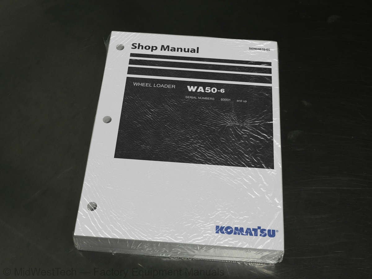
Komatsu WA50-6 Wheel Loader Service Manual
697 pages · Publication SEN04670-05
Added to your cart. View cart
- Models
- WA50-6
- Serial coverage
- 60001 and up
- Manual type
- Service Manual
- Pages
- 697
- Publication
- SEN04670-05
- Condition
- Brand new
What's inside
From the manual's own table of contents: 137 sections, 245 entries. See sample pages (PDF, 733 KB)
Show all 137 sections
Work equipment control lever linkage45 topics
- Hydraulic tank
- 2-unit gear pump
- Work equipment control valve
- Work equipment linkage
- Bucket
- Bucket positioner
- Work equipment cylinder
- Air conditioner
- Heater
- Canopy
- Machine monitor system
- Machine monitor
- HST electronic control system
- Electrical system (HST controller system)
- HST controller
- KOMTRAX system
- Engine start circuit
- Engine stop circuit
- Preheating circuit
- Travel mode selector switch
- Travel speed control dial
- Sensors
- Standard service value table for engine
- Standard service value table for chassis
- Tools for testing, adjusting, and troubleshooting
- Testing and adjusting engine speed
- Testing exhaust gas color
- Testing and adjusting valve clearance
- Testing compression pressure
- Testing engine oil pressure
- Testing and adjusting fuel injection timing
- Bleeding air from fuel circuit
- Check of installed condition of cylinder head and manifolds
- Check of engine piping for damage and looseness
- Check of muffler and muffler stack for looseness and damage
- Check of muffler function
- Testing, adjusting and replacing alternator belt
- Testing, adjusting and replacing air conditioner compressor belt
- Testing operating force of accelerator pedal
- Testing fuel level sensor
- Testing directional lever
- Testing and adjusting HST oil pressure
- Adjusting travel speed sensor
- Testing and adjusting steering wheel
- Testing and adjusting steering oil pressure
Engine does not stop56 topics
- Preheater does not operate normally
- Travel speed is low or high
- Parking brake omission alarm malfunctions
- Bucket positioner does not function or cannot be reset
- Travel direction cannot be changed normally
- Windshield wiper does not operate
- Window washer does not operate
- Headlamp, clearance lamp, tail lamp and license lamp do not light or go off
- Turn signal lamp does not light or go off
- Stop lamp does not light or go off
- Backup lamp does not light or go off
- Backup buzzer does not sound or stop sounding
- Horn does not sound or stop sounding
- Alarm buzzer does not sound or stop sounding
- Fuel level is not displayed normally
- Air conditioner does not work
- KOMTRAX system does not operate normally
- Method of using troubleshooting chart
- Failure phenomenon and cause table
- The machine does not start
- The travel speed is slow
- The traction force is weak
- Engine stalls when traveling or engine speed drops excessively
- Travel speed variable dial does not function
- The steering wheel does not turn
- The steering wheel is heavy
- Steering wheel shakes or jerks
- Machine deviates naturally to one side when traveling
- The brake does not work or does not work well
- The brake is not released or is dragged
- Parking brake does not work at all or sufficiently
- Parking brake is not reset or it drags
- The lift arm does not rise or lower
- The lift arm moves slowly or the lift arm rising force is insufficient
- When rising, the lift arm comes to move slowly at specific height
- The lift arm cylinder cannot hold down the bucket (The bucket rises in the air)
- Hydraulic drifts of the lift arm occur often
- The lift arm wobbles during operation
- When the control lever is switched from “HOLD” to “RAISE,” the lift arm falls temporarily
- The bucket does not tilt back
- The bucket moves slowly or the tilting-back force is insufficient
- The bucket comes to operate slowly in the midst of tilting-back
- The bucket cylinder cannot hold down the bucket
- Hydraulic drifts of the bucket occur often
- The bucket wobbles during travel with load (The work equipment valve is set to “HOLD”)
- When the control lever is switched from “HOLD” to “TILT,” the bucket falls temporarily
- The control levers of the lift arm and bucket do not move smoothly and heavy
- Method of using troubleshooting charts
- Starting performance is poor
- Engine does not start
- Engine does not pick up smoothly
- Engine stops during operations
- Engine does not rotate smoothly
- Engine lacks output (or lacks power)
- Exhaust smoke is black (incomplete combustion)
- Oil consumption is excessive (or exhaust smoke is blue)
Removal and installation of front monitor panel assembly7 topics
- Removal and installation of right side monitor panel assembly
- Removal and installation of HST controller assembly
- Removal and installation of KOMTRAX terminal assembly
- Hydraulic circuit diagram
- Electrical circuit diagram (1/2)
- Electrical circuit diagram (2/2)
- Connector list and stereogram
Inside this manual
Real pages from this service manual (697 pages). Open the sample pages (PDF, 732 KB)
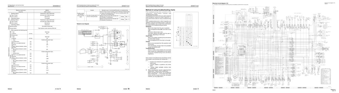
- Specifications, page 60: 100 Specification and technical data
- Diagram, page 460: 400 Troubleshooting of electrical system (E-mode)
- Troubleshooting, page 510: 600 Troubleshooting of engine (S-mode)
- Foldout diagram, page 693: Electrical circuit diagram (1/2)
Other manuals for this machine
Save 10% on 2 manuals, 15% on 3 or more. Other manuals for the WA50-6 are listed below. Editions cover different serial number ranges: check the serial coverage and tick only the ones that match your machine.
Added to your cart. View cart
This is a service manual
Here's how it compares to the other manual types.
Service manual
Factory repair procedures and technical information such as specifications, troubleshooting, and wiring and hydraulic diagrams, for the models and systems the manual covers. See What's inside for its topics.
Operator's manual
Safe operation, controls, maintenance schedules, lubrication points, inspections, and basic checks. Repair procedures are in the service manual.
Parts manual
Illustrated diagrams with factory part numbers for identifying components and ordering parts. Repair procedures are in the service manual.
Engine service manuals are sometimes sold separately, since certain machine models were offered with more than one engine option.
What it's used for
Factory manual for in-house farm and construction shop use. Straightforward, complete, and easy to follow. It contains the OEM information dealership service departments and parts counters use to diagnose problems, identify components, and perform maintenance or repairs correctly.
Service shops and owner/operators who repair their own equipment
Identifying correct parts and seeing how assemblies come apart and go back together
Keeping equipment running with less downtime
Factory manual, 697 pages
Quantity one is the manual described above.
Fast free USA shipping
Ships in 1 business day.
60-day returns
Free if the mistake is ours. A manual ordered in error must come back unopened in its shrink-wrap; you pay return shipping and a 20% restocking fee applies. Return policy
Binder not included
Manuals over about 300 pages may need a standard 3-ring binder, which you can buy locally to keep the pages organized for shop use.
Questions about model, serial number, engine coverage or contents? Contact us before purchasing and we'll help confirm it's the right manual. Please verify the manual type, machine model, serial number range and engine coverage before purchasing: manuals ordered in error carry a 20% restocking fee (return policy).