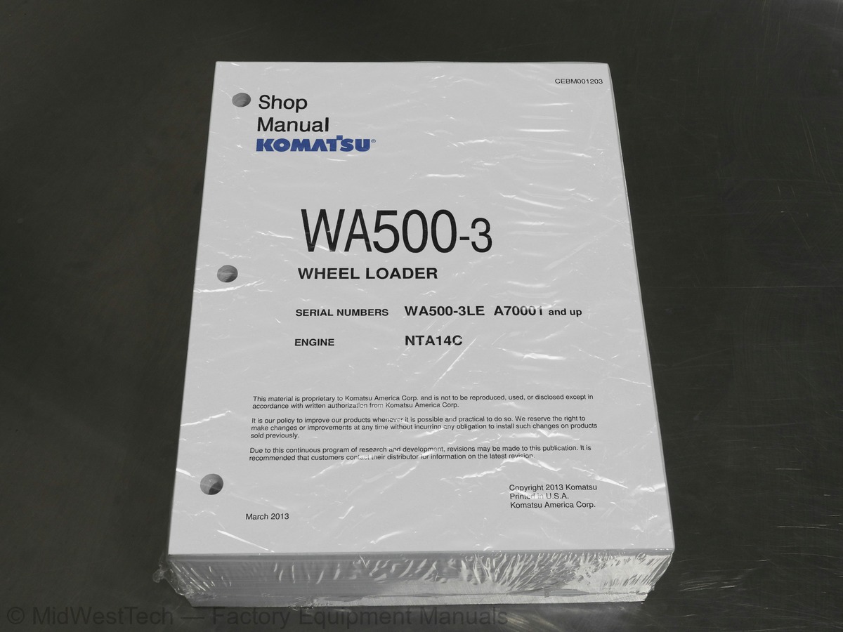
Komatsu WA500-3 Wheel Loader Service Manual
1,047 pages · Publication CEBM001203
Added to your cart. View cart
- Models
- WA500-3
- Serial coverage
- A70001 and up
- Manual type
- Service Manual
- Pages
- 1,047
- Publication
- CEBM001203
- Condition
- Brand new
What's inside
From the manual's own table of contents: 2 sections, 316 entries. See sample pages (PDF, 821 KB)
General46 topics
- GENERAL
- STRUCTURE AND FUNCTION
- TESTING, ADJUSTING, AND TROUBLESHOOTING
- DISASSEMBLY AND ASSEMBLY
- MAINTENANCE STANDARD
- OTHER
- TROUBLESHOOTING
- Points to remember when troubleshooting
- Sequence of events in troubleshooting
- Points to remember when carrying out maintenance
- Checks before troubleshooting
- Handling connectors
- Precautions when troubleshooting
- Method of reading troubleshooting tables
- Preventing recurrence of trouble
- Connector types and mounting locations
- Connection table for connector pin numbers
- Explanation of functions of electric control mechanism
- Transmission control system
- Main monitor system
- Maintenance monitor system
- ECSS (Electronically Controlled Suspension System) control system
- Joystick steering control system
- Method of displaying action and failure code
- Chart of action codes and failure codes, and re-enaction
- Transmission controller LED display
- Method of using judgement table
- Method of using judgement charts
- Method of using matrix troubleshooting tables
- Judgement table tor transmission controller system related parts
- Action taken by controller when abnormality occurs and problems on machine
- Electrical circuit diagram for transmission controller system
- lamp relay) is displayed
- is displayed
- Failure code [19] (Short circuit, disconnection in joystick directional switch system) is displayed
- Failure code [201 (Short circuit, disconnection in directional switch system) is displayed
- Failure code [211 (Short circuit, disconnection in range switch system) is displayed
- Failure code [221 (Disconnection in travel speed sensor system) is displayed
- Failure code [231 (Short circuit, disconnection in engine speed sensor system) is displayed
- Failure code [241 (Short circuit, disconnection in EEP ROM) is displayed
- Failure code [251 (Short circuit in transmission oil temperature system) is displayed
- Failure code [26] (Short circuit in F ECMV fill switch system) is displayed
- Failure code [27] (Short circuit in R ECMV fill switch system) is displayed
- Failure code [281 (Short circuit in 1st ECMV fill switch system) is displayed
- Failure code [291 (Short circuit in 2nd ECMV fill switch system) is displayed
- Failure code [301 (Short circuit in 3rd ECMV fill switch system) is displayed
TROUBLESHOOTING235 topics
- Failure code [311 (Short circuit in 4th ECMV fill switch system) is displayed
- Failure code [32] (Short circuit in F or R ECMV fill switch system) is displayed
- Failure code [33] (Short circuit in 1st, 2nd, 3rd, or 4th ECMV fill switch system) is displayed
- Hold switch system
- Kick-down switch system
- Transmission cut-off signal system
- Neutralizer relay signal system
- Buzzer signal system
- Network system
- Transmission controller power source system
- Short circuit in travel speed sensor system
- Disconnection in transmission oil temperature sensor system
- Disconnection in F ECMV fill switch system
- Disconnection in R ECMV fill switch system
- Disconnection in 1st ECMV fill switch system
- Disconnection in 2nd ECMV fill switch system
- Disconnection in 3rd ECMV fill switch system
- Disconnection in 4th ECMV fill switch system
- Trouble data display
- Electrical circuit diagram for machine monitor system
- Electrical circuit diagram for lamp and horn system
- Electrical circuit diagram for turn signal and hazard system
- Main monitor does not work
- lighted up
- Speedometer display does not work properly
- Abnormality in shift indicator
- Displays N even when directional lever is at F
- Displays N even when directional lever is at R
- directional lever is at F
- when directional lever is at F
- Does not display 1st - 4th
- High beam does not light up
- Turn signal display does not light up
- L.H. turn signal display does not light up
- R.H. turn signal display does not light up
- Abnormality in parking display
- Parking lamp display does not light up
- Parking lamp display stays lighted up
- Night lighting does not light up
- Abnormality in front working lamp
- Neither monitor display nor front working lamp light up
- Working lamp lights up but monitor display does not light up
- Monitor display lights up but working lamp does not light up
- Abnormality in rear working lamp
- Neither monitor display nor rear working lamp light up
- Abnormality in transmission cut-off
- not switched and display does not change
- out but cut-off function is actuated when pedal is depressed
- cut-off function is always actuated
- (transmission cut-off switch ON or OFF)
- cut off function is not actuated
- Abnormality in parking brake dragging warning
- flashes even when directional lever is at N
- does not light up even when directional lever is at position other than N
- continuously, or they are not actuated
- Actuated continuously
- Not actuated
- Abnormality in buzzer
- (during self-check)
- Buzzer always sounds
- Condition of monitor switches is not stored in memory
- Abnormality in failure display mode
- Does not enter failure display mode
- Count for time elapsed since failure in failure display mode does not advance
- Buzzer is not made to sound by transmission controller
- Abnormality in emergency steering normal display
- Emergency steering normal display does not light up
- Emergency steering normal display stays lighted up
- Abnormality in emergency steering actuation display
- Emergency steering actuation display does not light up
- Emergency steering actuation display stays lighted up
- Abnormality in auto-greasing system
- Forced greasing cannot be carried out
- Monitor display flashes rapidly (2 times/sec)
- When no more grease remains, monitor display flashes rapidly (2 times/sec)
- Monitor display flashes slowly (1time/sec), confirm that grease is not empty
- Monitor display goes out
- Abnormality in ECSS system
- Display does not change when switch is pressed
- Monitor display lights up but ECSS function does not work
- Failure code is not sent to main monitor (abnormality in network)
- for 3 seconds, maintenance monitor does not work
- No lamps on maintenance monitor light up
- Some lamps do not light up
- do not go out (even after 3 seconds)
- (within 3 seconds), no lamps on maintenance monitor go out
- When starting switch is turned ON (engine stopped), CHECK items flash
- Engine oil level display flashes
- Engine water level display flashes
- When starting switch is turned ON (engine started), CAUTION items flash
- Engine oil pressure display flashes
- Battery charge level display flashes
- Brake oil pressure display flashes
- Air cleaner display flashes
- CAUTION items are flashing but caution buzzer does not sound
- K-7 There is no abnormality in monitor display but caution buzzer sounds
- not flash
- CHECK lamp
- CAUTION lamp
- (CHECK lamp, CAUTION lamp) lights up
- monitor does not light up)
- Night lighting lights up even when lamp switch is OFF, night lighting stays lighted up
- Service meter does not work
- Service meter is running even when engine is stopped
- Abnormality in gauge items
- Abnormality in fuel gauge
- Abnormality in engine water temperature gauge
- Abnormality in torque converter oil temperature gauge
- Electrical circuit diagram for power supply, engine starting / stop system
- Electrical circuit diagram for parking brake system
- Electrical circuit diagram for boom kick-out and bucket positioner system
- Engine does not start
- Starting motor does not turn
- Starting motor turns
- Engine does not stop
- Engine stops when machine is traveling
- Not used
- Parking brake does not have effect
- Parking brake has no effect when parking brake switch is turned ON (actuated)
- (Does not work as emergency brake)
- Parking brake is applied when machine is traveling
- Parking brake is released when starting switch is turned ON
- (But parking brake works normally)
- Kick-down switch does not work
- shift operations)
- Kick-down is not canceled
- Boom kick-out cannot be used
- Abnormality in bucket positioner function
- Abnormality in lighting up of front working lamp
- Abnormality in lighting up of rear working lamp
- Power train
- Machine does not start
- Does not shift gear
- Excessive shock when starting machine of shifting gear
- Excessive time lag when starting machine of shifting gear
- Torque converter oil temperature is high
- Steering system
- Steering does not turn
- Steering does not turn (machine with joystick)
- Turning, response of steering is poor
- Turning, response of steering is poor (machine with joystick)
- Steering is heavy
- Joystick is heavy
- Steering wheel shakes or jerks
- Steering shakes or there is excessive shock (machine with joystick)
- Turning radius is different between left and right at maximum steering
- Brake system
- Wheel brakes do not work or braking effect is poor
- Wheel brakes are not released or brakes drag
- Parking brake does not work or braking effect is poor
- Parking brake is not released or brake drags (including emergency release system)
- Work equipment
- Neither boom nor bucket move
- Both boom and bucket are slow or lack power
- Boom does not move
- Boom is slow or boom lacks power
- Boom cannot be set to FLOAT or cannot be released from FLOAT
- Boom drops momentarily when control lever is operated from HOLD to RAISE
- Excesseve hydraulic drift of boom
- Bucket does not move
- Bucket is slow or lacks power
- Excesseve hydraulic drift of bucket
- ECSS does not work, and there is pitching and bouncing (machines with ECSS)
- Judgement table for controller electrical system
- Electrical circuit diagram for ECSS
- D-1 ECSS does not work
- Error code [d0] is displayed
- Error code [d1] is displayed
- Error code [d2] is displayed
- Error code [d3] is displayed
- No abnormality display is given
- D-2 ECSS cannot be canceled
- Judgement table for joystick controller system related parts
- Action taken by controller when abnormality occur
- Electrical circuit diagram for joystick system
- J- 1 Failure code [56] (short circuit, disconnection in caution relay output) is displayed
- J- 4 Failure code [59] (short circuit in steering right solenoid (HOT end) is displayed
- J- 5 Failure code [60] (short circuit in steering left solenoid (HOT end) is displayed
- system) is displayed (Not used)
- J- 9 Abnormality in power source, voltage
- Abnormality in joystick steering ON-OFF signal system
- Disconnection in steering right solenoid
- Disconnection in steering left solenoid
- Electrical circuit diagram for MDC (Multiple Display and Condition) monitor system
- When engine is running, engine oil level display shows “Abnormal
- When engine is running, battery electrolyte level display shows “Abnormal
- Abnormality in engine coolant level display
- Display shows “Abnormal
- Display shows “Disconnection
- Display shows “Short circuit
- Abnormality in brake oil pressure display
- When engine is running, display shows “Abnormal
- Abnormality in engine oil pressure display
- When engine is stopped or running, display shows “Disconnection
- Only when engine is stopped, display shows “Disconnection
- When starting switch is at “ON” (engine started), battery charge display shows “Abnormal
- When starting switch is at “ON” (engine started), air cleaner display shows “Abnormal
- CAUTION item display shows “Abnormal”, but alarm buzzer does not sound
- Monitor display does not show “Abnormality”, but alarm buzzer sounds
- CAUTION lamp) does not flash
- CAUTION lamp) lights up
- Service meter is running when engine is stopped
- Display shows “Disconnection” or low fuel level
- Display always shows FULL and does not go down
- Abnormality in engine coolant temperature gauge
- Display always shows lowest level and does not go up
- When starting switch is turned ON, monitor is not actuated (KOMATSU is not displayed
- Main monitor CHECK lamps do not light up
- Main monitor CHECK lamps light up
- before starting mode when engine is running
- Abnormality in MDC monitor display
- Display color is abnormal
- Display flickers
- Even when switch is operated, nothing functions
- Does not switch to TV/video mode
- Stays at PARKING BRAKE APPLIED display
- Display does not light up
- Abnormality in memory data
- Load meter data is not saved to memory
- Maintenance time is not saved to memory
- Engine speed stays at 0 rpm
- Pressure sensor display shows “Disconnection
- Sensor power source display also shows “Abnormal
- Only pressure sensor display shows “Disconnection
- Load meter cannot weigh load
- Cannot carry out calibration
- Can carry out calibration
- Abnormality in lever switch
- Sub-total switch does not work
- Cancel switch does not work
- Printer does not print out
- Abnormality in antenna system
- Abnormality in speaker system
- Abnormality in right speaker
- Abnormality in left speaker
DISASSEMBLY AND ASSEMBLY33 topics
- Removal of PPC valve assembly
- Installation of PPC valve assembly
- Disassembly of PPC valve assembly
- Assembly of PPC valve assembly
- Removal of main control valve assembly
- Installation of main control valve assembly
- Assembly of main control valve
- Removal of bucket cylinder assembly
- Installation of bucket cylinder assembly
- Removal of boom cylinder assembly
- Installation of boom cylinder assembly
- cylinders assembly
- assembly
- Removal of center hinge pin
- Installation of center hinge pin
- Removal of work equipment
- Installation of work equipment assembly
- Removal of bulkhead assembly
- Installation of bulkhead assembly
- Installation of engine hood assembly
- Removal of floor frame assembly
- Installation of floor frame assembly
- Removal of counterweight
- Installation of counterweight
- Removal of fuel tank assembly
- Installation of fuel tank assembly
- Removal of cab assembly
- Installation of cab assembly
- unit assembly
- condenser assembly
- Removal of receiver tank
- Installation of receiver tank
- compressor assembly
Inside this manual
Real pages from this service manual (1,047 pages). Open the sample pages (PDF, 820 KB)
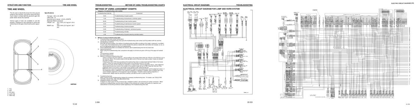
- Specifications, page 92: STRUCTURE AND FUNCTION
- Troubleshooting, page 444: METHOD OF USING TROUBLESHOOTING CHARTS
- Diagram, page 572: ELECTRICAL CIRCUIT DIAGRAMS
- Foldout diagram, page 225
Other manuals for this machine
Save 10% on 2 manuals, 15% on 3 or more. Other manuals for the WA500-3 are listed below. Editions cover different serial number ranges: check the serial coverage and tick only the ones that match your machine.
Added to your cart. View cart
This is a service manual
Here's how it compares to the other manual types.
Service manual
Factory repair procedures and technical information such as specifications, troubleshooting, and wiring and hydraulic diagrams, for the models and systems the manual covers. See What's inside for its topics.
Operator's manual
Safe operation, controls, maintenance schedules, lubrication points, inspections, and basic checks. Repair procedures are in the service manual.
Parts manual
Illustrated diagrams with factory part numbers for identifying components and ordering parts. Repair procedures are in the service manual.
Engine service manuals are sometimes sold separately, since certain machine models were offered with more than one engine option.
What it's used for
Factory manual for in-house farm and construction shop use. Straightforward, complete, and easy to follow. It contains the OEM information dealership service departments and parts counters use to diagnose problems, identify components, and perform maintenance or repairs correctly.
Service shops and owner/operators who repair their own equipment
Identifying correct parts and seeing how assemblies come apart and go back together
Keeping equipment running with less downtime
Factory manual, 1,047 pages
Quantity one is the manual described above.
Fast free USA shipping
Ships in 1 business day.
60-day returns
Free if the mistake is ours. A manual ordered in error must come back unopened in its shrink-wrap; you pay return shipping and a 20% restocking fee applies. Return policy
Binder not included
Manuals over about 300 pages may need a standard 3-ring binder, which you can buy locally to keep the pages organized for shop use.
Other editions and similar models
Questions about model, serial number, engine coverage or contents? Contact us before purchasing and we'll help confirm it's the right manual. Please verify the manual type, machine model, serial number range and engine coverage before purchasing: manuals ordered in error carry a 20% restocking fee (return policy).