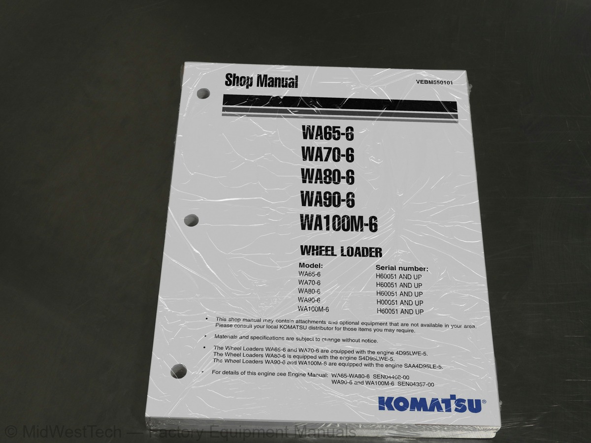
Komatsu WA65-6, WA70-6, WA80-6, WA90-6, WA100M-6 Wheel Loader Service Manual
427 pages · Publication VEBM550101
Added to your cart. View cart
What's inside
From the manual's own table of contents: 335 topics. See sample pages (PDF, 822 KB)
- Contens
- List of revised pages
- Safety notice
- Preparations for work
- Tipping up the driver's cab
- Tipping down the driver's cab
- Precautions during work
- Hydraulic system
- Foreword
- How to read the shop manual
- Volumes
- Distribution and updating
- Filing method
- Symbols
- Hoisting instructions
- Wire ropes
- Dimensions, weights and operating data
- Specifications
- WA65-6 – Specifications
- WA70-6 – Specifications
- WA80-6 – Specifications
- WA90-6 – Specifications
- WA100M-6 – Specifications
- Weight tables
Show all 335 topics
- WA65-6 – Weight table
- WA70-6 – Weight table
- WA80-6 – Weight table
- WA90-6 – Weight table
- WA100M-6 – Weight table
- Lubricants and operating mediums
- WA65-6, WA70-6 – Lubricants and operating mediums
- WA80-6 – Lubricants and operating mediums
- WA90-6 – Lubricants and operating mediums
- WA100M-6 – Lubricants and operating mediums
- Basic procedures of maintenance
- Fuel
- Coolant
- Grease
- Storing oil and fuel
- Filters
- Biodegradable hydraulic oils and lubricants
- Outline of electric system
- Torque list – Screws and nuts
- Powertrain
- Closed circuit
- Hydraulic drive system
- WA65-6, WA70-6 – Hydraulic drive system – 20 km/h
- WA80-6 – Hydraulic drive system – 20 km/h and 30 km/h
- Variable displacement pump (HST pump)
- Regulating valve (DA valve)
- WA65-6, WA70-6, WA80-6 - Charge pump pressure relief valve - 20km/h
- WA80-6 ,WA90-6, 100M-6 - Charge pump pressure relief valve - 30km/h
- Control cylinder
- 4/3 Way valve with direction control solenoids
- Pressure cut-off valve
- Safety & charge valve
- Towing
- Variable displacement motor (HST motor with HA Control)
- Hydraulic diagram HST motor A6VM80 (or 160) HA1R1
- Directional shuttle valve
- Auto inch valve diagram (option)
- HST motor with DA Control
- Hydraulic diagram HST Motor A6VM107(160)DA2
- Drive shaft
- Front axle – Mounting
- WA65-6, WA70-6 – Front axle mounting
- Rear axle – Mounting
- Front axle
- WA65-6, WA70-6 – Front axle with outer disc brake as service brake and parking brake
- WA80-6 – Front axle with inner disc brake as service brake and outer disc brake as parking brake
- Rear axle with transfer box
- WA65-6, WA70-6, WA80-6 – Rear axle with transfer box
- WA90-6, WA100M-6 – Rear axle with transfer box
- Trasfer box TB172
- Limited slip differential
- Limited slip differential – Locking value 25%
- Locking differential
- Locking differential – Locking value 100%
- Wheel hub – Font axle and rear axle
- Service and parking brake – Front axle
- WA65-6, WA70-6 – Service and parking brake
- Service and parking brake circuit
- WA65-6, WA70-6 – Service and parking brake circuit
- WA80-6 – Service and parking brake circuit
- WA90-6, WA100M-6 – Service and parking brake circuit
- Service brake assembly
- WA65-6, WA70-6 – Service brake assembly
- WA80-6 – Service brake assembly
- WA90-6, WA100M-6 – Service brake assembly
- Main-brake valve
- Steering articulation joint
- Steering system
- WA65-6, WA70-6 – Hydraulic circuit diagram of steering system
- WA80-6 – Hydraulic circuit diagram of steering system
- WA90-6, WA100M-6 – Hydraulic circuit diagram of steering system
- Priority valve
- Orbit-roll-valve
- Steering relief valve
- Work equipment hydraulic
- WA65-6, WA70-6 – Travel, steering and work hydraulics
- WA80-6 – Travel, steering and work hydraulics
- WA90-6, WA100M-6 – Travel, steering and work hydraulics
- Operation of PPC-valve
- Servo pressure regulating valve
- Emergency Lowering System
- Main control valve
- Main control valve WA90-6, WA100M-6
- Lift cylinder
- WA80-6 – Lift cylinder
- WA90-6 – Lift cylinder
- WA100M-6 – Lift cylinder
- Dump cylinder
- WA80-6 – Dump cylinder
- WA90-6 – Dump cylinder
- WA100M-6 – Dump cylinder
- Steering cylinder
- WA65-6, WA70-6 – Steering cylinder
- WA80-6 – Steering cylinder
- WA90-6, WA100M-6 – Steering cylinder
- Loader Linkage with quick-coupler
- WA65-6, WA70-6 – Loader Linkage with quick-coupler
- WA80-6, WA90-6, WA100M-6 – Loader Linkage with quick-coupler
- Quick-coupler
- WA80-6 – Quick-coupler
- Monitor display
- WA90-6, WA100M-6 – Monitor display
- Special monitor functions
- Monitor panel adjustment
- Adjustment switches
- Adjustment table
- WA80-6 Tire table
- WA90-6 Tire table
- WA100M-6 Tire table
- Reading error codes WA90-6, WA100M-6
- Trouble Codes and Cummins Fault Codes
- Sensors
- Engine oil pressure sensor
- Fuel level sensor
- Engine coolant temperature sensor
- Brake oil reservoir sensor
- Pre-heater
- Engine stop / start / preheating circuit
- Electrical fuses and relays
- Fuses
- Relays
- Engine room
- Diagrams
- Wiring diagrams
- Hydraulic circuit diagram
- Air conditioner (option)
- Introduction
- Function
- The coolant circuit
- The condenser
- The vaporizer
- The filter dryer
- Installation of air conditioner
- Safety when handling coolants
- Operating the air conditioner
- Maintenance of the air conditioner
- Regular maintenance
- Instructions for filling
- Exchange of magnetic clutch
- Exchange of compressor
- Troubleshooting
- Standard value table for engine
- WA65-6, WA70-6, WA80-6 - Standard value table for engine
- WA90-6, WA100M-6 - Standard value table for engine
- Standard value table for chassis
- WA65-6 - Standard value table for chassis
- WA70-6 - Standard value table for chassis
- WA80-6 - Standard value table for chassis
- WA90-6 - Standard value table for chassis
- WA100M-6 - Standard value table for chassis
- Standard value table for electrical parts
- Test certificate
- WA65-6 - Test certficate
- WA70-6 - Test certificate
- WA80-6 - Test certificate
- WA90-6 - Test certificate
- WA100M-6 - Test certificate
- Valve lash clearance
- WA90-6, WA100M-6 - Valve lash clearance
- Engine compression test
- WA65-6, WA70-6, WA80-6 - Engine compression test
- WA90-6, WA100M-6 - Engine compression test
- Fuel system
- WA65-5, WA70-6, WA80-6 - Testing and adjusting fuel injection timing
- WA90-6, WA100M-6 - Testing fuel pressure
- WA90-6, WA100M-6 - Bleeding air from fuel circuit
- WA90-6, WA100M-6 - Testing fuel system for leakage
- V-belt tension
- Engine RPM
- Testing travel speed
- Engine stall torque RPM
- Engine stall torque RPM, test with the hydrostatic drive
- Engine stall torque RPM, test with hydrostatic drive and working hydraulics
- Feed pump (and servo oil pressure)
- Hydraulic pressure cut-off
- Working hydraulic pressure
- Steering oil pressure
- Testing
- Adjusting
- Operating time for steering wheel
- Operating force of steering wheel
- Disc brake (foot brake)
- Brake
- Main brake valve – basic adjustment
- Brake efficiency
- Measuring the stopping distance
- Parking brake efficiency
- Bleeding/ filling up the brake circuit
- WA65-6, WA70-6 - Bleeding/ filling up the brake circuit
- Ventilation / filling up the brake circuit
- WA80-6, WA90-6, WA100M-6 - Ventilation / filling up the brake circuit
- Cabin - adjustment
- Comments
- Starter assembly
- Removal of starter assembly
- Installation of starter assembly
- Alternator assembly
- Removal of alternator assembly
- Installation of alternator assembly
- Radiator assembly
- Removal of radiator assembly
- Installation of radiator assembly
- Fan assembly
- Removal of fan assembly
- Installation of fan assembly
- Water pump assembly
- Removal of water pump assembly
- Installation of water pump assembly
- Fuel tank assembly
- Removal and installation of fuel tank assembly
- Installation
- Engine cover assembly
- Removal of engine cover assembly
- Installation of engine cover assembly
- Engine cover support assembly
- Removal of engine cover support assembly
- Installation of engine cover support assembly
- Engine assembly
- Removal of engine assembly
- Installation of engine assembly
- Clutch assembly
- Removal of clutch assembly
- Installation of clutch assembly
- Main brake valve assembly
- Removal of main brake valve assembly
- Installation of main brake valve assembly
- Priority valve assembly
- Removal of priority valve assembly
- Installation of priority valve assembly
- Orbit-roll-valve assembly
- Removal of orbit-roll-valve assembly
- Installation of orbit-roll-valve assembly
- Counterweight assembly
- Removal of counterweight assembly
- Installation of counterweight assembly
- Main control valve assembly - WA65-6, WA70-6, WA80-6
- Removal of control valve assembly
- Installation of main control valve assembly
- Main control valve assembly - WA90-6, WA100M-6
- Removal of main control valve assembly
- Pilot valve assambly WA90-6, WA100M-6
- Removal of pilot valve assembly
- Installation of pilot valve assembly
- Monitor assembly
- Removal of monitor assembly
- Installation of monitor assembly
- Articulated joint assembly
- Removal of articulated joint assembly
- Installation of articulated joint assembly
- Variable motor assembly
- Removal of variable motor assembly
- Installation of variable motor assembly
- Rear axle assembly
- Removal of rear axle assembly
- Installation of rear axle assembly
- Front axle assembly
- Removal of front axle assembly
- Installation of front axle assembly
- Brake disc group
- Disassembly
- Assembly
- Brake caliper
- Hydraulic principle of operation
- Differential position
- Mechanical principle of operation
- Caliper removal
- Disassembly (calliper removed)
- Caliper reassembly
- Replacement of guide protective covers
- Pad replacement
- Brake group - wheel shaft
- Rear axle
- Trunnions group and flange
- Epicyclic reduction gear group
- Wheel hub
- Differential support group
- Bevel gear marking test
- Differential locking group
- Differential group (100% Differential Lock)
- Differential group (LSD 25%)
- Pinion group
- Transmission box
- Variable displacement pump assembly
- Removal of variable displacement pump assembly
- Installation of variable displacement pump assembly
- Hydraulic pump assemblies
- Removal of the two hydraulic pump assemblies
- Installation of hydraulic pump assembly
- Turbocharger assembly - WA80-6, WA90-6, WA100M-6
- Removal of the turbocharger
- Installation of the turbocharger
- Quick coupler assembly
- Removal of quick coupler assembly
- Installation of quick coupler assembly
- Steering cylinder assembly
- Removal of steering cylinder assembly
- Installation of steering cylinder assembly
- Lift cylinder assembly
- Removal of lift cylinder assembly
- Installation of lift cylinder assembly
- Dump cylinder assembly
- Removal of dump cylinder assembly
- Installation of dump cylinder assembly
- Replacing windows in driver’s cab
- Stuck glass
- Door and side windows
- Door window assembly
- Side window assembly
- Hydraulic circuit diagram – WA65-6, WA70-6
- Hydraulic circuit diagram – WA80-6
- Hydraulic circuit diagram – WA90-6, WA100M-6
Inside this manual
Real pages from this service manual (427 pages). Open the sample pages (PDF, 821 KB)
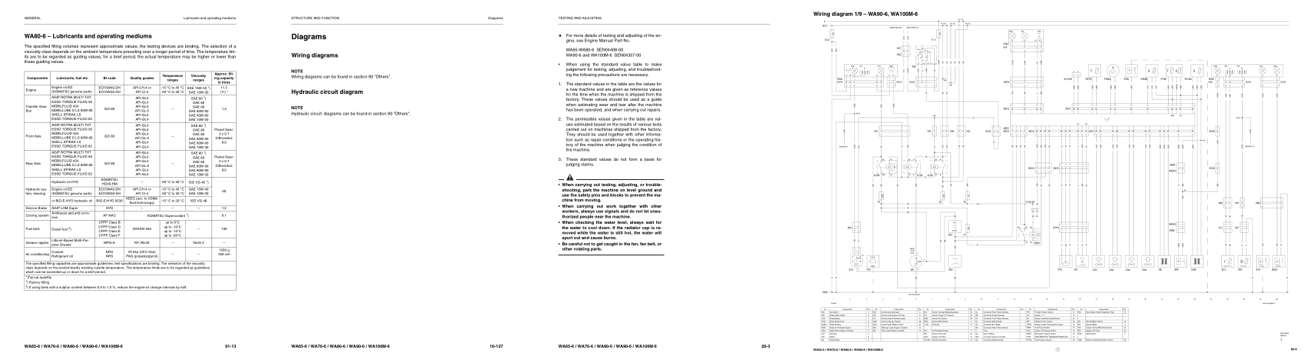
- Specifications, page 44: GENERAL
- Diagram, page 182: Diagrams
- Troubleshooting, page 206: TESTING AND ADJUSTING
- Foldout diagram: WA65-6 / WA70-6 / WA80-6 / WA90-6 / WA100M-6
Other manuals for this machine
Save 10% on 2 manuals, 15% on 3 or more. Other manuals for the WA65-6, WA70-6, WA80-6, WA90-6, WA100M-6 are listed below. Editions cover different serial number ranges: check the serial coverage and tick only the ones that match your machine.
Added to your cart. View cart
This is a service manual
Here's how it compares to the other manual types.
Service manual
Factory repair procedures and technical information such as specifications, troubleshooting, and wiring and hydraulic diagrams, for the models and systems the manual covers. See What's inside for its topics.
Operator's manual
Safe operation, controls, maintenance schedules, lubrication points, inspections, and basic checks. Repair procedures are in the service manual.
Parts manual
Illustrated diagrams with factory part numbers for identifying components and ordering parts. Repair procedures are in the service manual.
Engine service manuals are sometimes sold separately, since certain machine models were offered with more than one engine option.
What it's used for
Factory manual for in-house farm and construction shop use. Straightforward, complete, and easy to follow. It contains the OEM information dealership service departments and parts counters use to diagnose problems, identify components, and perform maintenance or repairs correctly.
Service shops and owner/operators who repair their own equipment
Identifying correct parts and seeing how assemblies come apart and go back together
Keeping equipment running with less downtime
Factory manual, 427 pages
Quantity one is the manual described above.
Fast free USA shipping
Ships in 1 business day.
60-day returns
Free if the mistake is ours. A manual ordered in error must come back unopened in its shrink-wrap; you pay return shipping and a 20% restocking fee applies. Return policy
Binder not included
Manuals over about 300 pages may need a standard 3-ring binder, which you can buy locally to keep the pages organized for shop use.
Questions about model, serial number, engine coverage or contents? Contact us before purchasing and we'll help confirm it's the right manual. Please verify the manual type, machine model, serial number range and engine coverage before purchasing: manuals ordered in error carry a 20% restocking fee (return policy).