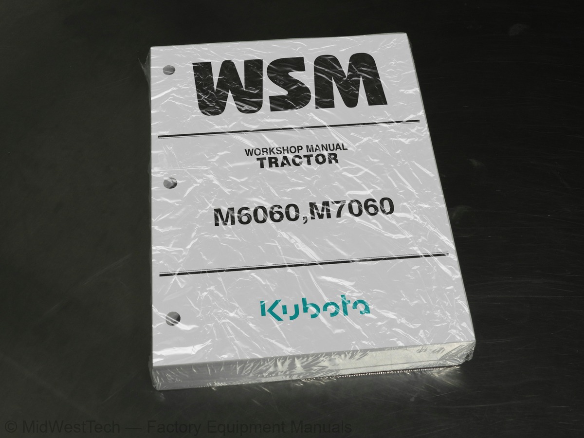
Kubota M6060, M7060 Tractor Service Manual
639 pages · Publication 9Y111-08280
Added to your cart. View cart
- Models
- M6060, M7060
- Manual type
- Service Manual
- Pages
- 639
- Publication
- 9Y111-08280
- Condition
- Brand new
What's inside
From the manual's own table of contents: 221 sections, 393 entries. See sample pages (PDF, 692 KB)
TRACTOR IDENTIFICATION1 topic
- MODEL NAME AND SERIAL NUMBERS
(4) DPF Muffler Number2 topics
- E4B ENGINE
- CYLINDER NUMBER
HANDLING PRECAUTIONS FOR ELECTRICAL PARTS AND WIRING6 topics
- WIRING
- BATTERY
- FUSE
- CONNECTOR
- HANDLING OF CIRCUIT TESTER
- COLOR OF WIRING
TIGHTENING TORQUES3 topics
- GENERAL USE SCREWS, BOLTS AND NUTS
- STUD BOLTS
- HYDRAULIC FITTINGS
(3) Adaptors, Elbows and Others1 topic
- METRIC SCREWS, BOLTS AND NUTS
THREADS1 topic
- PLUGS
CHECK AND MAINTENANCE14 topics
- DAILY CHECK
- CHECK POINTS OF INITIAL 50 HOURS
- CHECK POINTS OF EVERY 50 HOURS
- CHECK POINTS OF EVERY 100 HOURS
- CHECK POINTS OF EVERY 200 HOURS
- CHECK POINT OF EVERY 400 HOURS
- CHECK POINTS OF EVERY 500 HOURS
- CHECK POINT OF EVERY 600 HOURS
- CHECK POINTS OF EVERY 1000 HOURS
- CHECK POINTS OF EVERY 1500 HOURS
- CHECK POINTS OF EVERY 3000 HOURS
- CHECK POINTS OF EVERY 1 YEAR
- CHECK POINTS OF EVERY 2 YEARS
- OTHERS
SPECIAL TOOLS3 topics
- SPECIAL TOOLS FOR ENGINE
- SPECIAL TOOLS FOR TRACTOR
- SPECIAL TOOLS FOR AIR CONDITIONER UNIT
ENGINE BODY9 topics
- CYLINDER BLOCK
- COOLING JACKET
- HALF-FLOATING HEAD COVER
- CYLINDER HEAD
- SCREWS PER EACH CYLINDER ASSEMBLING STRUCTURE
- CENTER DIRECT INJECTION SYSTEM (E-CDIS)
- GEAR TRAIN CONFIGURATION
- PISTON
- BUILT-IN DYNAMIC BALANCER
Show all 221 sections
LUBRICATING SYSTEM1 topic
- OIL COOLER
COOLING SYSTEM2 topics
- THERMOSTAT
- BOTTOM BYPASS SYSTEM
FUEL SYSTEM5 topics
- OVERVIEW
- SUPPLY PUMP
- RAIL
- INJECTOR
- ENGINE CONTROL SYSTEM
EGR SYSTEM3 topics
- EGR VALVE
- REED VALVE
- EGR COOLER
AFTER TREATMENT SYSTEM1 topic
- AFTER TREATMENT DEVICES
CHECKING, DISASSEMBLING AND SERVICING1 topic
- CHECKING AND ADJUSTING
(5) EGR Cooler1 topic
- PREPARATION
(7) Separating Engine From Front Axle Frame1 topic
- DISASSEMBLING AND ASSEMBLING
(11)Crankshaft and Crankcase1 topic
- SERVICING
STRUCTURE2 topics
- F18/R18 SPEED TRANSMISSION MODEL
- LIVE PTO-GROUND PTO MODEL (ITA MODEL)
POWER TRAIN FOR TRAVELING GEAR1 topic
- SHUTTLE SHIFT SECTION
(3) Hydraulic Clutch Pack1 topic
- HYDRAULIC SHUTTLE VALVE
(2) Operation3 topics
- MAIN GEAR SHIFT SECTION
- HI-LO-CREEP SHIFT SECTION
- SHIFT FORK ROD AND FORK
LUBRICATION FOR TRANSMISSION1 topic
- HYDRAULIC SHUTTLE MODEL
POWER TRAIN FOR PTO SYSTEM3 topics
- PTO GEAR SECTION
- GROUND PTO AND LIVE PTO SECTION (ITA MODEL)
- PTO HYDRAULIC CLUTCH SECTION
POWER TRAIN FOR 4WD2 topics
- 4WD HYDRAULIC CLUTCH SECTION
- 4WD OIL FLOW
CHECKING AND ADJUSTING1 topic
- SHUTTLE LEVER
(2) Engine Start Condition2 topics
- CLUTCH PEDAL FREE TRAVEL
- GEAR SHIFTING LINKAGE
(2) Range/Creep Gear Shift4 topics
- SHUTTLE VALVE
- 2WD-4WD CLUTCH
- PTO CLUTCH
- ACCELERATOR SECTION
DISASSEMBLING AND ASSEMBLING1 topic
- HYDRAULIC SHUTTLE VALVE AND SOLENOID VALVE ASSEMBLY
(4) Solenoid Valve Assembly1 topic
- PREPARATION FOR SEPARATING EACH BLOCK
(5) Bonnet (CABIN Model)2 topics
- SEPARATING ENGINE AND CLUTCH HOUSING CASE
- SEPARATING CLUTCH HOUSING CASE FROM TRANSMISSION CASE
(3) Separating Transmission Case5 topics
- SEPARATING TRANSMISSION CASE
- DAMPER DISC
- HYDRAULIC SHUTTLE CLUTCH
- SHIFT COVER
- CLUTCH HOUSING
(6) Removing DT Propeller Shaft1 topic
- TRANSMISSION CASE
(1) Removing Solenoid Valve Assembly4 topics
- PREPARATION FOR DISASSEMBLING AND ASSEMBLING VALVE
- SEPARATING REAR AXLE (ROPS MODEL)
- SEPARATING REAR AXLE (CABIN MODEL)
- DISASSEMBLING REAR AXLE
SERVICING2 topics
- BEARING
- PLANETARY GEAR
TRAVELLING BRAKE3 topics
- STRUCTURE (HYDRAULIC BRAKE MODEL)
- MASTER CYLINDER ASSEMBLY
- HYDRAULIC TRAILER BRAKE VALVE
PARKING BRAKE3 topics
- INNER STRUCTURE
- FIXING FLOW
- CHECKING AND ADJUSTING
(3) Parking Brake1 topic
- DISASSEMBLING AND ASSEMBLING
(9) Parking Brake Gear1 topic
- SERVICING
(2) Traveling Brake2 topics
- CHECKING AND ADJUSTING
- DISASSEMBLING AND ASSEMBLING
(4) Disassembling Differential Gear (LSD)2 topics
- SERVICING
- CHECKING AND ADJUSTING
(2) Hydraulic Pump1 topic
- PREPARATION
(5) Removing Steering Cylinder1 topic
- DISASSEMBLING AND ASSEMBLING
(3) Disassembling Steering Cylinder3 topics
- SERVICING
- F18/R18 SPEED TRANSMISSION MODEL (ROPS MODEL)
- F18/R18 SPEED TRANSMISSION MODEL (CABIN MODEL)
HYDRAULIC CIRCUIT1 topic
- TOTAL HYDRAULIC CIRCUIT
THREE POINT HITCH HYDRAULIC SYSTEM3 topics
- THREE POINT HITCH HYDRAULIC CIRCUIT
- HYDRAULIC BLOCK
- LINKAGE MECHANISM
(3) Mixed Control8 topics
- HYDRAULIC CYLINDER
- HYDRAULIC PUMP
- RELIEF AND SAFETY VALVE
- POSITION AND DRAFT CONTROL LINKAGE
- AUXILIARY CONTROL VALVE LINKAGE
- OIL COOLER CHECK VALVE (FOR F18/R18 SPEED TRANSMISSION MODEL)
- HYDRAULIC PUMP
- THREE POINT HITCH HYDRAULIC BLOCK ASSEMBLY
(2) Removing 3-point Hitch Hydraulic Block (CABIN Model)9 topics
- HYDRAULIC LINKAGE
- CONTROL VALVE
- HYDRAULIC CYLINDER
- RELIEF VALVE
- SAFETY VALVE
- TOP LINK BRACKET
- LIFT ARM AND LIFT ARM SHAFT
- LOWERING SPEED ADJUSTING VALVE AND CHECK VALVE
- LIFT ARM AND TOP LINK BRACKET
ELECTRICAL CIRCUIT DIAGRAM1 topic
- ROPS MODEL
(6) Engine Control System 2 (Engine ECU)1 topic
- CABIN MODEL
STARTING SYSTEM1 topic
- SYSTEM OUTLINE AND ELECTRICAL CIRCUIT
INSTRUMENT PANEL3 topics
- INDICATION ITEMS OF METER PANEL
- EASY CHECKER™
- LCD MONITOR INDICATION
(3) Testing Mode1 topic
- ECO 40 km/h FUNCTION
(2) Components2 topics
- PTO SPEED LIMITER (IF EQUIPPED 540ECONOMY)
- CONSTANT RPM MANAGEMENT SWITCH WITH INDICATOR (WORK CRUISE)
LIGHTING SYSTEM1 topic
- COMPONENTS
TRAILER SOCKET1 topic
- BATTERY, FUSES, GROUNDING AND CONNECTOR
(4) Connector6 topics
- MAIN SWITCH
- GLOW PLUG
- STARTER MOTOR
- ALTERNATOR
- THROTTLE SENSOR
- METER PANEL
(6) Selecting Tractor Specification1 topic
- TRACTOR ECU
(2) Connector Pin (44 Pin)3 topics
- TRAVELING SWITCH AND SENSOR
- ENGINE SWITCH AND SENSOR
- RELAYS
(2) Relays1 topic
- LIGHTING SWITCHES AND FLASHER UNIT
(6) Front/Rear Work Light (CABIN Model)1 topic
- SOLENOID VALVE
(2) Trailer Brake (ITA Model)6 topics
- OPC (OPERATOR PRESENCE CONTROL) SYSTEM
- PTO SWITCH
- STARTER MOTOR
- ALTERNATOR
- FUSE (SLOW BLOW 100 A) FOR CABIN MODEL
- STARTER
AIR CONDIITIONING SYSTEM7 topics
- STRUCTURE
- COMPRESSOR
- AIR CONDITIONER UNIT
- SYSTEM CONTROL
- AIR FLOW
- AIR CONTROL VENT
- ELECTRICAL SYSTEM
PRECAUTIONS AT REPAIRING REFRIGERANT CYCLE1 topic
- HANDLING OF SERVICE TOOLS
CHECKING AND CHARGING REFRIGERANT CYCLE2 topics
- CHECKING WITH MANIFOLD GAUGE
- DISCHARGING, EVACUATING AND CHARGING
(4) Checking Charge Refrigerant Amount1 topic
- CHECKING AND ADJUSTING
(14)Rear Wiper Motor (If equipped)1 topic
- DISASSEMBLING AND ASSEMBLING
(7) Wiper Motor1 topic
- SERVICING
Inside this manual
Real pages from this service manual (639 pages). Open the sample pages (PDF, 691 KB)

- Specifications, page 127: GENERAL
- Troubleshooting, page 442: HYDRAULIC SYSTEM
- Diagram, page 514: ELECTRICAL SYSTEM
- Color page: ENGINE
- Color page: TRANSMISSION
- Foldout diagram: HYDRAULIC SYSTEM
This is a service manual
Here's how it compares to the other manual types.
Service manual
Factory repair procedures and technical information such as specifications, troubleshooting, and wiring and hydraulic diagrams, for the models and systems the manual covers. See What's inside for its topics.
Operator's manual
Safe operation, controls, maintenance schedules, lubrication points, inspections, and basic checks. Repair procedures are in the service manual.
Parts manual
Illustrated diagrams with factory part numbers for identifying components and ordering parts. Repair procedures are in the service manual.
Engine service manuals are sometimes sold separately, since certain machine models were offered with more than one engine option.
What it's used for
Factory manual for in-house farm and construction shop use. Straightforward, complete, and easy to follow. It contains the OEM information dealership service departments and parts counters use to diagnose problems, identify components, and perform maintenance or repairs correctly.
Service shops and owner/operators who repair their own equipment
Identifying correct parts and seeing how assemblies come apart and go back together
Keeping equipment running with less downtime
Factory manual, 639 pages
Quantity one is the manual described above.
Fast free USA shipping
Ships in 1 business day.
60-day returns
Free if the mistake is ours. A manual ordered in error must come back unopened in its shrink-wrap; you pay return shipping and a 20% restocking fee applies. Return policy
Binder not included
Manuals over about 300 pages may need a standard 3-ring binder, which you can buy locally to keep the pages organized for shop use.
Questions about model, serial number, engine coverage or contents? Contact us before purchasing and we'll help confirm it's the right manual. Please verify the manual type, machine model, serial number range and engine coverage before purchasing: manuals ordered in error carry a 20% restocking fee (return policy).