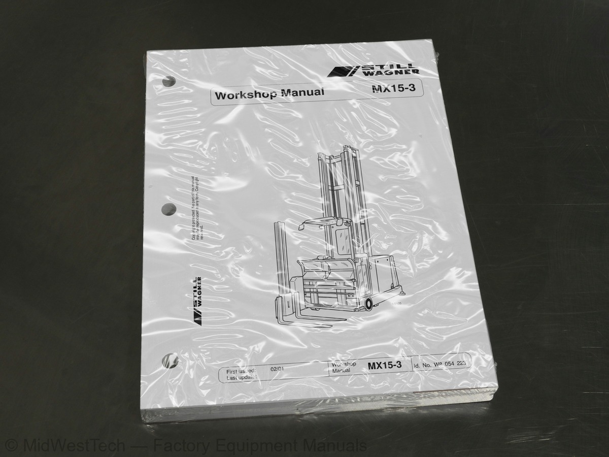
Linde MX15-3 Forklift Service Manual
228 pages · Publication W8-054-223
Added to your cart. View cart
- Models
- MX15-3
- Manual type
- Service Manual
- Pages
- 228
- Publication
- W8-054-223
- Condition
- Brand new
What's inside
From the manual's own table of contents: 192 topics. See sample pages (PDF, 449 KB)
- • List of chapters
- • Guide to components
- Guide to information plates and vehicle number
- Hydraulic settings
- Vehicle speed
- • Outside aisle
- • Inside aisle
- General
- Technical data for the drive motor
- Drive mor terminals
- carbon brush yoke
- Carbon brush monitoring
- Replacing the carbon brushes
- Checking the brush springs
- Removing the drive motor
- Installing the drive motor
- Drive motor maintenance
- Replacing the drive wheel
- Removing the drive wheel
- Oil change
- Removing the gear
- Function
- Removal
- Replacing the brake linings
Show all 192 topics
- Adjusting the brake clearance
- Mechanical brake release
- Testing the brake coils
- Continuous release of the second stage
- Measuring the braking deceleration
- Checking the braking deceleration
- Adjusting the braking deceleration
- Adjusting the steering
- • General
- • Adjusting sequence
- to the centre position
- • Adjusting the rotary force at the handwheel
- position
- • Adjusting potentiometers R11/R12
- • Adjusting the setpoint potentiometers
- • Adjusting the actual value potentiometer
- • Adjusting the max. steering angle
- • Correction of straight-on
- Rail guidance
- Free travel
- • Teaching-in the wheel position display
- Steering controller
- • Description
- • Guide to the potentiometer and LEDs
- • Service switch
- • Pin assignment
- • Main current terminals
- Steering motor
- • Terminal designations on terminal board
- • Replacing the carbon brushes
- • Emergency steering
- • Maintenance
- Removing the mast
- Installing the mast
- Mast table
- Description
- Pin assignment
- Terminals
- Block diagram
- Signal processing
- Response of the main contactors
- Control OK
- Temperature monitor fo the drive and pump motors
- • Testing the temperature sensors
- Temperature monitor for the travel and pump controller
- Carbon brush monitor for the drive and pump motors
- Incremental encoder monitor
- • Testing the incremental encoder of the drive motor
- • Testing the incremental encoder of the pump motor
- Operating elements
- Operating console board
- Keyboard boards 1, 2 and 3
- Operating console display
- • Basic display
- • Operating hours
- • Remaining battery capacity
- • Wheel position display
- • Display LED for manual steering
- • Status and maintenance symbols
- • "Deadman switch not actuated" display
- • "Creep speed" display
- • "2-handed operation not actuated" display
- • "Barrier open" display
- • "Maintenance" display
- • "LR80 error" display
- • "Acknowledgement required" display
- • "Reserve1" display
- • "Reserve2" display
- • Error display
- • Information display
- • Switching-on test
- • Switching over the operating console display
- • LR80 operating status display
- Replacing the setpoint potentiometer
- • Removing the setpoint potentiometer
- • Installing the setpoint potentiometer
- • Rough adjustment of the setpoint potentiometer
- • Fine adjustment of the setpoint potentiometer
- • Teaching-in the setpoint potentiometer
- LR80 board (option)
- Safety relays K33 and K34
- Safety relay K35
- Key switch relay K36
- Relay K37 (steering error)
- Enable hydraulics" signal
- Chain monitoring
- Adaptation of the steering setpoint
- Control of the electromagnetic brake
- Adaptation of incremental encoder signals
- Structure
- Pin assignment X1
- Coil holder suppression
- Spacing distance
- Contact pressure
- Electrical connections
- Technical data
- Location
- Identification
- Monitor
- Safety instructions
- Description of errors
- Removing and installing the distance sensor
- • 1. Replacing the potentiometer
- • 2. Replacing the cable
- • 3. Replacing the incremental encoder
- • 4. Replacing the belt
- • 5. Replacing the spring
- Monitoring
- Commissioning
- Deleting teaching-in values
- Preparation for teaching in
- Teaching in the main lift distance sensor
- Teaching in the additional lift distance sensor
- Teaching in the swivelling distance sensor
- Teaching in the side shift distance sensor
- Reference sequence for the main lift
- Reference sequence for the additional lift
- Functional elements
- Setting the maximum pressure
- Parameterising the main lift
- Soiling indicator
- High presure filter
- • Changing the filter - removal
- • Changing the filter - installation
- Removing the chassis valve block
- Fine control of lowering main lift
- Adjusting work
- Parameterising the ancilliary movements
- Technical data for the pump motor
- Pump motor terminals
- Temperature sensor integrated in carbon brush yoke
- Pump motor maintenance
- Checking for leaks
- Removing the pump
- Oil level indicator
- Maintenance
- Adjusting work on the TLH
- Adjusting the tooth profile play
- Adjusting the eccentric rollers for the overshift function
- Adjusting the swivel shaft for the additional lift
- Removing the lift carriage
- Adjusting the radial play on the lift carriage
- Adjusting the axial play on the lift carriage
- Adjusting the potentiometer for side shifting
- Adjusting the poentiometer for swivelling
- Adjusting the 90° swivelling range
- Adjusting the switching lug for side shifting
- Adjusting the limit switches for swivelling
- Adjusting the magnetic sensors
- Travel function
- Steering function
- Main lift function
- Additional lift function
- Side shift function
- Swivel function
- Synchronous swivel-shift movement 180°
- Synchronous swivel-shift movement 90°
- CAN bus error
- General errors
- Automatic braking at end of aisle function (EASS)
- Option errors
- Travel and pump controller errors (FPS)
- Power supply function
- • Battery voltage
- • 1+battery voltage after key switch
- • 1+battery voltage after 1+24V
- • EMERGENCY-STOP chain
- • 2+battery voltage
Inside this manual
Real pages from this service manual (228 pages). Open the sample pages (PDF, 449 KB)
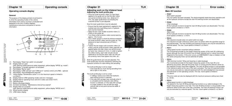
- Diagram, page 87: Operating console display
- Specifications, page 177: Chapter 31
- Troubleshooting, page 198: Chapter 35
This is a service manual
Here's how it compares to the other manual types.
Service manual
Factory repair procedures and technical information such as specifications, troubleshooting, and wiring and hydraulic diagrams, for the models and systems the manual covers. See What's inside for its topics.
Operator's manual
Safe operation, controls, maintenance schedules, lubrication points, inspections, and basic checks. Repair procedures are in the service manual.
Parts manual
Illustrated diagrams with factory part numbers for identifying components and ordering parts. Repair procedures are in the service manual.
Engine service manuals are sometimes sold separately, since certain machine models were offered with more than one engine option.
What it's used for
Factory manual for in-house farm and construction shop use. Straightforward, complete, and easy to follow. It contains the OEM information dealership service departments and parts counters use to diagnose problems, identify components, and perform maintenance or repairs correctly.
Service shops and owner/operators who repair their own equipment
Identifying correct parts and seeing how assemblies come apart and go back together
Keeping equipment running with less downtime
Factory manual, 228 pages
Quantity one is the manual described above.
Fast free USA shipping
Ships in 1 business day.
60-day returns
Free if the mistake is ours. A manual ordered in error must come back unopened in its shrink-wrap; you pay return shipping and a 20% restocking fee applies. Return policy
Questions about model, serial number, engine coverage or contents? Contact us before purchasing and we'll help confirm it's the right manual. Please verify the manual type, machine model, serial number range and engine coverage before purchasing: manuals ordered in error carry a 20% restocking fee (return policy).