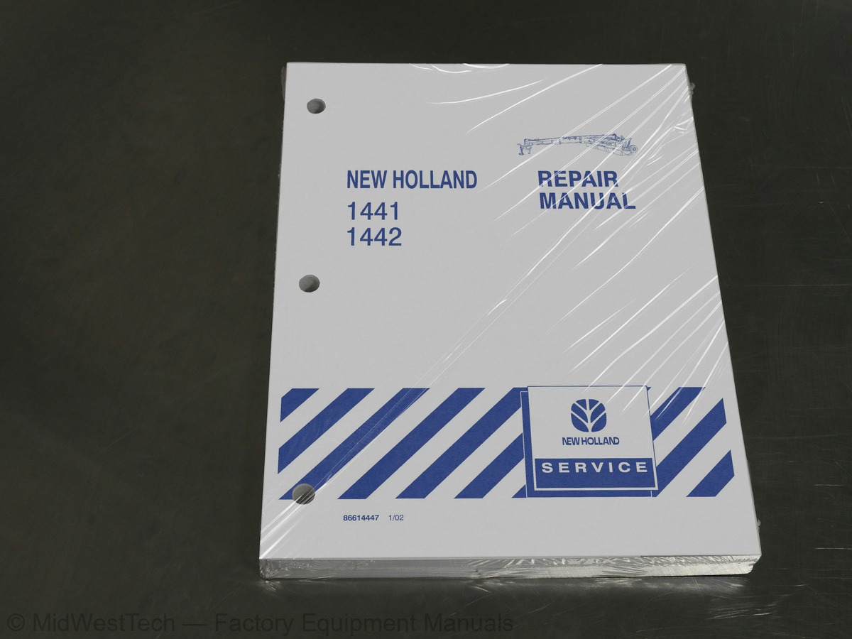
New Holland 1441, 1442 Disc Mower Conditioner Service Manual
350 pages · Publication 86614447
Added to your cart. View cart
What's inside
From the manual's own table of contents: 115 topics. See sample pages (PDF, 434 KB)
- Special Tools
- Specifications (Model 1441)
- Specifications (Model 1442)
- Lubrication
- Recommended Lubricants and Coolants
- Minimum Hardware Tightening Torques
- Installation of Adjustable Fittings
- Standard Torque Data for Hydraulic Tubes and Fittings
- Pipe Thread Fitting Torque
- Installation of ORFS (O-ring Flat Faced) Fittings
- Driveline (Standard Tongue)
- Introduction
- Primary PTO
- Intermediate PTO
- Jackshaft
- Secondary PTO
- Slide Lock
- Auto-lok Slide Lock
- Standard Driveline Guards
- U-joints: Swivel Hitch Units
- Labor Guide
- Slip Clutch
- Overrunning Clutch
- Swivel Hitch Gearboxes
Show all 115 topics
- Upper Gear Box
- Upper Gearbox and Neck Assembly
- Lower Gear Box
- Lower Gearbox and Neck Assembly
- Lower Gearbox, Neck Assembly, and Upper Gearbox
- Hydraulic Diagram
- Bleeding Air from the Lift Cylinders
- Lift Cylinder Removal
- Master Cylinder - Disassembly
- Master Cylinder - Inspection
- Master Cylinder - Assembly
- Slave Cylinder - Disassembly
- Slave Cylinder - Inspection
- Slave Cylinder - Assembly
- Header Tilt Cylinder Removal
- Header Tilt Cylinder Disassembly
- Header Tilt Cylinder Assembly
- Header Tilt Cylinder Installation
- Tongue Swing Cylinder Removal
- Tongue Swing Cylinder Disassembly
- Tongue Swing Cylinder Assembly
- Tongue Swing Cylinder - Installation
- Hood Removal
- Hood Installation
- Hood Liner Removal
- Hood Liner Installation
- Trailing Lights
- Description
- Installing #9603575 Socket
- Trailer Connector Repair
- Lighting Control Box - Removal and Installation
- Model 1441/1442 Wiring Schematic
- Discs
- Knife And Bolt Inspection
- Disc Knives
- Degree Twist Knives
- V Knives
- Knife Replacement
- Crop Lifter Replacement (Model 1441 Only)
- Rock Guards
- Skid Shoes
- Cutter Bar Inspection/Failure Analysis
- Top Cap Removal
- Inspection
- Top Cap Installation
- Cutter Bar Removal
- Cutter Bar Installation
- Cutter Bar Bayonet Bushing - Replacement
- Cutter Bar Disassembly
- Cutter Bar Reassembly
- Disc Module - Disassembly
- Disc Module - Assembly
- Cutter Bar Drive Shaft - Removal
- Cutter Bar Drive Shaft - Disassembly
- Cutter Bar Drive Shaft - Assembly
- Left Pedestal Shaft - Disassembly
- Left Pedestal Shaft - Assembly
- Center Pivoting Gearbox - Removal
- Center Pivoting Gearbox - Disassembly
- Center Pivoting Gearbox - Assembly
- Gearbox Support Plate Bushing Replacement
- Center Pivoting Gearbox - Installation
- Guidance Link Shimming
- Right-hand Gearbox - Removal
- Right-hand Gearbox - Disassembly
- Right-hand Gearbox - Assembly
- Right-hand Gearbox - Installation
- Gearbox Specifications
- Model 1441 Conditioner Drive Gearbox - Removal
- Model 1441 Conditioner Drive Gearbox - Disassembly
- Model 1441 Conditioner Drive Gearbox - Assembly
- Model 1441 Conditioner Drive Gearbox - Installation
- Conditioner Belt Adjustment
- Conditioner Belt Replacement
- Conditioner Roll Drive Shaft - Removal
- Conditioner Roll Drive Shaft - Disassembly
- Conditioner Roll Drive Shaft - Assembly
- Conditioner Roll Drive Shaft - Installation
- Lower Conditioner Roll - Removal
- Lower Conditioner Roll - Installation
- Upper Conditioner Roll - Removal
- Upper Conditioner Roll - Installation
- Conditioner Roll Tension System
- Conditioner Roll Tension System - Assembly
- Conditioner Belt
- Flail Removal
- Flail Installation
- Rotor Removal
- Rotor Installation
- Model 1441 Safety Decals
- Model 1442 Safety Decals
Inside this manual
Real pages from this service manual (350 pages). Open the sample pages (PDF, 433 KB)

- Repair procedure, page 72: SECTION 31 - IMPLEMENT POWER TAKE OFF (PTO) - CHAPTER 3
- Diagram, page 152: SECTION 55 - ELECTRICAL SYSTEM - CHAPTER 1
This is a service manual
Here's how it compares to the other manual types.
Service manual
Factory repair procedures and technical information such as specifications, troubleshooting, and wiring and hydraulic diagrams, for the models and systems the manual covers. See What's inside for its topics.
Operator's manual
Safe operation, controls, maintenance schedules, lubrication points, inspections, and basic checks. Repair procedures are in the service manual.
Parts manual
Illustrated diagrams with factory part numbers for identifying components and ordering parts. Repair procedures are in the service manual.
Engine service manuals are sometimes sold separately, since certain machine models were offered with more than one engine option.
What it's used for
Factory manual for in-house farm and construction shop use. Straightforward, complete, and easy to follow. It contains the OEM information dealership service departments and parts counters use to diagnose problems, identify components, and perform maintenance or repairs correctly.
Service shops and owner/operators who repair their own equipment
Identifying correct parts and seeing how assemblies come apart and go back together
Keeping equipment running with less downtime
Factory manual, 350 pages
Quantity one is the manual described above.
Fast free USA shipping
Ships in 1 business day.
60-day returns
Free if the mistake is ours. A manual ordered in error must come back unopened in its shrink-wrap; you pay return shipping and a 20% restocking fee applies. Return policy
Binder not included
Manuals over about 300 pages may need a standard 3-ring binder, which you can buy locally to keep the pages organized for shop use.
Other editions and similar models
Questions about model, serial number, engine coverage or contents? Contact us before purchasing and we'll help confirm it's the right manual. Please verify the manual type, machine model, serial number range and engine coverage before purchasing: manuals ordered in error carry a 20% restocking fee (return policy).