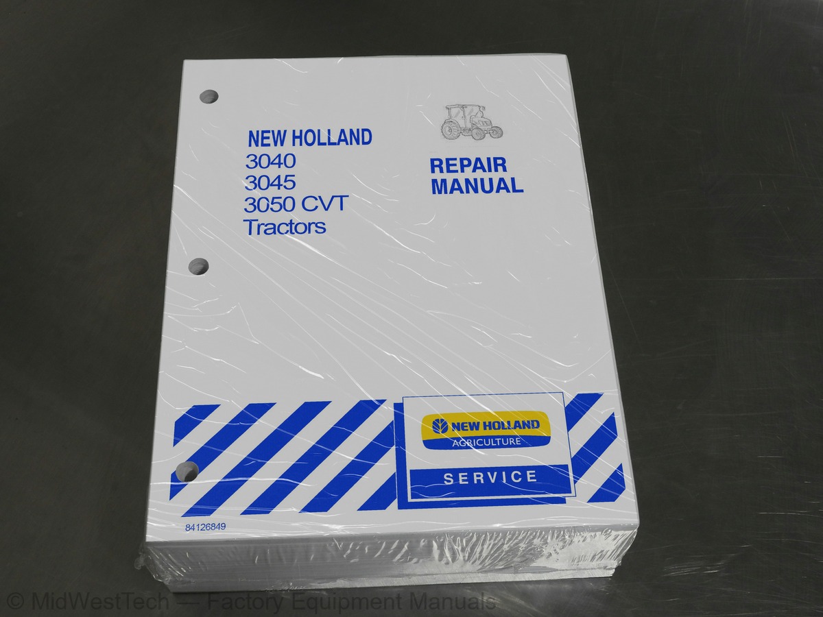
New Holland 3040, 3045, 3050 CVT Tractor Service Manual
1,229 pages · Publication 84126849
Added to your cart. View cart
What's inside
From the manual's own table of contents: 384 sections, 700 entries. See sample pages (PDF, 487 KB)
Show all 384 sections
Separating the Tractor at the Engine - Front Transmission Box2 topics
- Removal
- Installation 60
Fan, Water Pump, and External Oil Tube1 topic
- Removal
Air Inlet Manifold1 topic
- Removal
Fuel Shutoff Solenoid1 topic
- Removal
Engine Timing Gear Cover, Timing Gears, and Cam Shaft1 topic
- Timing Gear Cover Removal
Timing Gears and Camshaft1 topic
- Removal
Flywheel1 topic
- Removal
Backplate and Oil Seal1 topic
- Removal
Cylinder Head2 topics
- Disassembly
- Inspection and Repair
Cylinder BIOCK 2.0.62 topics
- Disassembly and Inspection
- Pin to Bushing Clearance
Pistons, Rings, and Connecting Rod1 topic
- ASSEMDIY 2.6
Main Bearing3 topics
- Assembly
- ReEMOval 2.1
- Installation 20
Camshaft3 topics
- Disassembly
- Inspection
- Assembly
Front Oil Seal and Steering Pump Seal1 topic
- Replacement
Crankshaft and Bearing Holder1 topic
- Installation
Rear Oil Seal and Backplate1 topic
- Installation 2.0
Flywheel1 topic
- Installation
Pistons and Connecting Rods1 topic
- Installation
Balancer Assembly (N844 and N844L Engines)4 topics
- Installation 2.0
- Balancer Shims
- Installation 6.0
- Installation
Fuel Injection Pump1 topic
- Installation 0
Hydraulic Oil Pump1 topic
- Installation
Valve Clearance1 topic
- Adjustment
Glow Plug and Connector1 topic
- Installation 0.0
Description of Operation - Engine Lubrication System4 topics
- Construction and Function
- Maintenance
- Installation and Adjustment
- Check oo
Radiator2 topics
- Inspection and Repair
- Installation
Thermostat 2.0.03 topics
- Inspection and Repair
- Installation 6.0
- Installation
Delivery Valves 101 topic
- Installation 60
Fuel PUMP2 topics
- Installation (New Pump or Drive Component)
- Spill-timing Procedure
Fuel Screw/High Idle1 topic
- Adjustment
Description of Operation - Governor4 topics
- Disassembly
- Assembly/Adjustment
- Removal
- Installation
Troubleshooting - Engine Breather Valve1 topic
- Separating the Front Transmission Box from the Differential Housing
Front Transmission Box1 topic
- ASSEMbIY 2
Forward/Reverse Shuttle Clutch2 topics
- Disassembly
- ASSeEMbly 0.0
Description of Operation1 topic
- Operating Speeds
Overhaul2 topics
- Removal
- Inspection
Hydraulic PUMP3 topics
- Disassembly
- Inspection 00
- ASSEMDIy 2.6
Hydraulic Oil Pressure Sensor2 topics
- Removal
- TeStING 6
Secondary Pulley Output Shaft2 topics
- Removal
- Inspection
Park Lock Control1 topic
- Inspection
Transmission Release Control2 topics
- Removal
- Inspection
Primary Pulley Oil Distribution Pipe1 topic
- Installation
Secondary Pulley Output Shaft1 topic
- Installation 6.0
Rear Pto/Fwd Hydraulic Valves1 topic
- Installation 6.0
Hydraulic Oil Pressure Sensor1 topic
- Installation
Hydraulic PUMP1 topic
- Installation 60
Description of Operation - FWD Front Axle2 topics
- Lubricate Every 50 Hours - SuperSteer™
- Lubricate Every 50 Hours - Standard FWD
Gear Reduction Drop Box1 topic
- Disassembly
Front Axle and Differential 0.0.0.01 topic
- Disassembly
Drive Pinion1 topic
- Disassembly
Drive Pinion1 topic
- Assembly
Differential Gear 0.0.01 topic
- Assembly 2.0.0
Axle and Differential1 topic
- Assembly
Differential Case Bearing Preload1 topic
- Check and Adjustment
Bevel Gear-to-Pinion Backlash1 topic
- Check 0
Sensitrack 2.0.0.02 topics
- Automatic Position (Engaged)
- Full Time Front Wheel Drive (Locked Down)
SuperSteer Axle 2.0.2.02 topics
- Removal
- Disassembly
Drive PINION1 topic
- ASSEMDIy 2.0
Differential Gear1 topic
- Assembly
Differential Case Bearing Preload1 topic
- Check and Adjustment
Gear Reduction Box1 topic
- Assembly
Bevel Gear-To-Pinion Backlash1 topic
- Check 2
SuperSteer Axle 2.01 topic
- Installation
Mechanical Operation1 topic
- Disengage
Differential2 topics
- REMOVAl 2
- Inspection 1.0.2.0
Drive Pinion2 topics
- Secondary Pulley Output Shaft - Removal
- Park Lock Control - Removal
Primary Pulley Oil Distribution Pipe6 topics
- Removal 2.0
- Inspection
- Transmission Release Control - Removal
- Inspection 00
- Installation 0.0
- Replacement Shim Amount (S2) Calculation
Ring Gear and Pinion Gear Pattern Specification and Adjustment1 topic
- Transmission Release Control - Installation
Primary Pulley Oil Distribution Pipe3 topics
- Secondary Pulley Output Shaft - Installation
- Seal Removal Tool
- Installation
PTO Activation Electrohydraulic Circuit4 topics
- Switched Battery Power Stud
- PTO Clutch Solenoid
- ADIC Instrument Cluster
- Rear PTO Speed Sensor
Hydraulic Fluid Flow1 topic
- PTO Clutch Assembly
PTO Hydraulic Block1 topic
- Test Procedure
PTO Hydraulic Block6 topics
- Removal
- Disassembly
- Inspection 0
- Installation
- Removal 1.0
- Inspection
PTO Cover Components3 topics
- Inspection 1.0
- ASSEMDIy 20
- Installation
Rear PTO Inductive Speed Sensor2 topics
- Replacement
- Power Flow Diagram for the CVT Transmission with Mid PTO
Mid PTO1 topic
- Inspection 0
Mid PTO Components1 topic
- Installation
BrakeS 2.04 topics
- Removal 1.0
- Disassembly
- Installation
- Adjustment 1.0.0.0
Description of Operation - Hydraulic Pump and Filter3 topics
- Disassembly
- Inspection and Repair
- Installation 2.0
Hydraulic Control Valve1 topic
- Lifting Position 0.0
Control Valve Internal Linkage1 topic
- Position Control - Raise Mode (Viewed From Left Side of Tractor)
Rear Lift External Controls2 topics
- Disassembly
- ASSEMbIY
Rear Lift Internal Controls6 topics
- Disassembly
- Inspection 1.0.0
- Assembly
- Inspection
- Disassembly
- Assembly
Control Valve Adjustments3 topics
- Sensitivity Adjustment
- Position Control Lever Adjustment
- Internal Push Rod Adjustment
Main System Relief Valve1 topic
- Servicing Faulty Relief Valve
Rear Remote Fluid Flow Diagrams2 topics
- Float
- LOWED
Front Remote (Two Spool) Loader Control Valve Fluid Flow Diagrams6 topics
- Bucket Control - Dumping/Lift Control - Neutral
- Bucket Control - Dumping Regen/Lift Control - Neutral
- Bucket Control - Roll Back/Lift Control - Neutral
- Bucket Control - Neutral/Lift Control - Raising
- Bucket Control - Neutral/Lift Control - Lowering
- Bucket Control - Neutral/Lift Control - Float
Two Spool Remote Valve4 topics
- Disassembly
- Inspection 0.0.0
- ASSEMDIy 2.6
- Installation 0.0
Rear Remote (Three Position Valve) (Non-denten)1 topic
- Inspection
Four Position Valve With Detent and Float3 topics
- Disassembly
- Assembly
- Detent Kick-out Adjustment
Power Steering Operation - Standard 4WD3 topics
- Fluid Flow - Neutral Position 2.0.0.0
- Fluid Flow - Left Turn 2.0
- Fluid Flow - Right Turn 2.0.0
Lubrication 2.2.63 topics
- Lubricate Every 50 Hours - Standard 4WD
- Removal
- Disassembly
Steering Cylinder - Standard 4WD1 topic
- Installation
Steering Cylinders2 topics
- Fluid Flow - Left Turn
- Fluid Flow - Right Turn
Lubricate Every 50 Hours4 topics
- Disassembly
- Inspection
- ASSEMbDly 2.1
- Installation 60
Power Steering Control Motor2 topics
- Rotor and Fixed Ring
- Pressure Relief Valve
Steering Control Motor3 topics
- Disassembly
- Inspection
- Installation
Power Steering PUMP5 topics
- Removal
- Disassembly
- Inspection and Repair
- Assembly
- Installation
Service Precautionary Statements2 topics
- General
- Preventing Mixing of Service Equipment
Refrigerant Extraction and Recycling Equipment7 topics
- Using Extraction Equipment
- Using Recycling Equipment
- RECOVETY 2
- Using a Manifold Gauge Set
- Checking Refrigerant for Excess Air
- Containers for Storing Recycled Refrigerant
- Disposal of Empty or Near-empty Disposable Containers
Applicable SAE Standards1 topic
- Related SAE Standards
Belt Replacement1 topic
- Specification
HVAC Controls 2.22 topics
- Removal
- Installation
Heater ValVe 21 topic
- Installation
CONdeENSEr 11 topic
- Removal
Evaporator/Heater Core Replacement3 topics
- Disassembly
- ASSEMbly 6.0
- Installation
Blower Motor/Blower Motor Resistor3 topics
- Disassembly
- Assembly
- Installation
Low Pressure Switch1 topic
- Replacement
A/C Compressor1 topic
- ReEMOvVal 2.0
Clutch Breakdown1 topic
- Compressor Repaired Internally and Reinstalled in the System
Clutch Head Repair8 topics
- Keyed Shaft Armature Removal
- Rotor Assembly Removal
- Field Coil Assembly Removal
- Field Coil Assembly Installation
- Keyed Shaft Armature Assembly Installation
- Replacement of Shaft Seal
- Valve Plate Removal
- Valve Plate and Cylinder Head Installation
Wiring Harnesses3 topics
- GroundS
- Removal
- Installation 0
Main Fuse1 topic
- Replacement
Key SWitch4 topics
- Removal 2
- Stop Position (Not Shown)
- Start Position
- Installation 0.0
Multi Function Stalk Switch (Lights, Turn Signals, Horn)6 topics
- Stalk Switch Testing
- Removal
- Installation 0.0
- Forward / Reverse Shuttle Terminal Identification
- Removal 1.0
- Installation 0
Headlight1 topic
- Replacement
Work Light Switch2 topics
- On” Position
- Installation
Hazard Light Switch3 topics
- Testing
- Off Position 0.0
- On” Position 2.0
Program Set Switch3 topics
- Enter Position “ON” 2.0.6
- Home Position “ON” 20.0
- Installation
Program Select Switch8 topics
- Removal
- TeSting 2
- UP Position “ON” 2.2
- DOWN Position “ON” 2.0.2
- ON” Position
- Installation
- HI Position “ON
- LOW Position “ON” 1.0
Speed Select Switch2 topics
- LOW Position “ON” . 20
- Installation 0
2QWD/4WD select switch5 topics
- ReEMOVAl 2
- AWD Position “ON” 2.0.0
- 2WD Position “ON
- PRESET Position “ON” 2.0.0.2
- SET Position “ON
PTO Activation Switch3 topics
- Switch Pushed Down “OFF” Position
- Switch Replacement
- Installation 6.0
Rear (Main) PTO Safety Switch1 topic
- Removal
Mid PTO Switch (Optional)4 topics
- Removal
- Retracted Position (PTO “ON”)
- Extended Position (PTO “OFF”)
- Installation 2.0
Brake Switch/Cruise Control Release Switch4 topics
- Removal
- Extended Position
- Retracted Position
- Installation 2.0
Seat Safety Switch2 topics
- Description
- Removal
Park Brake Safety Switch4 topics
- Removal
- Retracted Position (Not Shown)
- Extended Position 0.0.0.0
- Installation
Micro Relay Block Location1 topic
- Removal
Main Power Relay Location4 topics
- Removal
- Cab HVAC Relay
- Diode Testing
- Installation
Glow Plug Timer4 topics
- ReEMOval 2
- Installation 60
- Terminal Identification and Function
- Installation 6.0
Fuel Level Sending Unit1 topic
- Installation
Engine Coolant Temperature Sending Unit3 topics
- TeSting 2
- Coolant Temperature
- Sending Unit Temperature
Main Harness (Cab Connectors)2 topics
- Cab Power Connector C43P Identification and Function (C43P-C43R)
- Cab Signal Connector C44P Identification and Function (C44P-C44R)
Main Harness (Chassis Connectors)2 topics
- Chassis Harness Connector C3P Identification and Function (C3P-C3R)
- Chassis Harness Connector C2P Identification and Function (C2P-C2R)
MPH or Km/h1 topic
- Setting the Time
ADIC Fault Codes 2.13 topics
- (Transmission Related)
- PTO Indicator Light and PTO Speed Display
- Tachometer/Engine Speed
Alternator3 topics
- Description of Operation
- Charging Circuit
- Principle of IC Regulator
Alternator Component Testing and Inspection8 topics
- Stator
- Rectifier Assembly
- Alternator Brushes
- Alternator BearingS
- Drive Pulley
- Alternator Frames
- Alternator Bench Check
- Installation
Starter Components10 topics
- Starter Motor Assembly
- Starter Solenoid
- Pinion Clutch 1.0
- Removal
- Armature 10
- Brush Holder
- Field Coil
- Starter Solenoid
- No Load Test
- Installation
Inside this manual
Real pages from this service manual (1,229 pages). Open the sample pages (PDF, 487 KB)

- Color page, page 550
Other manuals for this machine
Save 10% on 2 manuals, 15% on 3 or more. Other manuals for the 3045 are listed below. Editions cover different serial number ranges: check the serial coverage and tick only the ones that match your machine.
Added to your cart. View cart
This is a service manual
Here's how it compares to the other manual types.
Service manual
Factory repair procedures and technical information such as specifications, troubleshooting, and wiring and hydraulic diagrams, for the models and systems the manual covers. See What's inside for its topics.
Operator's manual
Safe operation, controls, maintenance schedules, lubrication points, inspections, and basic checks. Repair procedures are in the service manual.
Parts manual
Illustrated diagrams with factory part numbers for identifying components and ordering parts. Repair procedures are in the service manual.
Engine service manuals are sometimes sold separately, since certain machine models were offered with more than one engine option.
What it's used for
Factory manual for in-house farm and construction shop use. Straightforward, complete, and easy to follow. It contains the OEM information dealership service departments and parts counters use to diagnose problems, identify components, and perform maintenance or repairs correctly.
Service shops and owner/operators who repair their own equipment
Identifying correct parts and seeing how assemblies come apart and go back together
Keeping equipment running with less downtime
Factory manual, 1,229 pages
Quantity one is the manual described above.
Fast free USA shipping
Ships in 1 business day.
60-day returns
Free if the mistake is ours. A manual ordered in error must come back unopened in its shrink-wrap; you pay return shipping and a 20% restocking fee applies. Return policy
Binder not included
Manuals over about 300 pages may need a standard 3-ring binder, which you can buy locally to keep the pages organized for shop use.
Other editions and similar models
Questions about model, serial number, engine coverage or contents? Contact us before purchasing and we'll help confirm it's the right manual. Please verify the manual type, machine model, serial number range and engine coverage before purchasing: manuals ordered in error carry a 20% restocking fee (return policy).